Simultaneous Perfect Bending and Polarization Rotation of Electromagnetic Wavefront using Chiral Gradient Metasurfaces
Abstract
We introduce chiral gradient metasurfaces that allow perfect transmission of all the incident wave into a desired direction and simultaneous perfect rotation of the polarization of the refracted wave with respect to the incident one. Besides using gradient polarization densities which provide bending of the refracted wave with respect to the incident one, using metasurface inclusions that are chiral allows the polarization of the refracted wave to be rotated. We suggest a possible realization of the proposed device by discretizing the required equivalent surface polarization densities realized by proper helical inclusions at each discretization point. By only using a single optically thin layer of chiral inclusions, we are able to unprecedentedly deflect a normal incident plane wave to a refracted plane wave at with power efficiency which is accompanied by a polarization rotation. The proposed concepts and design method may find practical applications in polarization rotation devices at microwaves as well as in optics, especially when the incident power is required to be deflected.
I INTRODUCTION
From the beginning of the 21st century, the investigation of metasurfaces, i.e., optically thin layers of arrayed subwavelength inclusions, to shape the wavefront of the electromagnetic waves at will is dramatically increased compared to that of bulky metamaterials Albooyeh et al. (2016); Achouri et al. (2015); Asadchy et al. (2016); Chen et al. (2016); Cheng et al. (2013); Faniayeu et al. (2017); Markovich et al. (2013); Menzel et al. (2010); Pfeiffer and Grbic (2014); Pfeiffer et al. (2016); Safari et al. (2017); Vehmas et al. (2013); Xiao et al. (2015); Zheng et al. (2018); Zhu et al. (2017); Capolino et al. (2013); Glybovski et al. (2016); Tretyakov (2015); Wong et al. (2016); Kazemi et al. ; Mohammadi Estakhri and Alù (2016); Alaee et al. (2016); Albooyeh et al. (2015); Guo et al. (2017); Rajaei et al. (2019). This is because metasurfaces have in general less losses and easier manufacturing processes compared to bulky engineered metamaterials. Quite recently, by applying the so-called generalized laws of reflection and refraction, specifically designed phase gradient metasurfaces achieved about of transmitted power for manipulation of transmitted waves Yu et al. (2011); Shalaev et al. (2015). Such designs were suffering from a lack of degrees of freedom for controlling the polarization of the refracted wave. Subsequent attempts, based on generalized boundary conditions, accomplished more efficient power operation (about ) and also enabled manipulation of polarization Monticone et al. (2013); Pfeiffer and Grbic (2013). Simultaneous control of reflected or transmitted phase and amplitude is achieved using anisotropic metasurface elements with enough degrees of freedom as the Y shaped elements in Veysi et al. (2015) leading to both deflection and polarization rotation, yet without devising a robust method that maximizes power transfer.
Most recently, a theoretical scheme for gradient (spatially dispersive) metasurfaces, which offers a perfect control of refracted/reflected waves (i.e., 100% power efficiency), was introduced in the seminal studies in Refs. Asadchy et al. (2016); Mohammadi Estakhri and Alù (2016); Wong et al. (2016). Based on that scheme, metasurface designs several interesting applications involving wavefront control were proposed (see e.g., Refs. Elsakka et al. (2016); Chen et al. (2017); Asadchy et al. (2017); Emani et al. (2017); Wong et al. (2018); Rabinovich and Epstein (2018)). However, yet no work has been carried out based on that scheme for the concurrent control of both the direction and polarization of refracted wavefront. Therefore, we found it timely and essential to introduce the realization of gradient metasurfaces that not only desirably deflect the wavefront but also manipulate its polarization at will.
Metasurfaces for both polarization conversion and wavefront manipulation may find a wide range of applications in problems in frequency ranges spanning from microwaves to optics. For instance, metasurface based polarization rotators are suitable to replace bulky wave plates (quarter, half wavelength, etc.). Next, metasurface based wave deflectors are handy candidates to take over the commonly used bulky optical beam splitters that deflect the wavefront of light (deflection with power efficiency) in optical systems Pfeiffer and Grbic (2014); Yu et al. (2012); Wu et al. (2014). Moreover, polarization selective metasurfaces are applied for coding the information into different polarization states Selvanayagam and Eleftheriades (2016); Li et al. (2016); Kim and Eleftheriades (2016). Furthermore, they may find practical applications as both polarization rotators or wavefront deflectors at microwave frequencies especially in the design of antenna systems, etc Selvanayagam and Eleftheriades (2016); Pfeiffer et al. (2016); Jia et al. (2016); Farmahini-Farahani and Mosallaei (2013).
Here, we synthesize a planar transmitting metasurface which perfectly deflects the normal (with respect to the metasurface plane) incoming wavefront by and concurrently rotates its polarization by , while we express that a similar design procedure can be performed for any arbitrary angles of deflection and any polarization rotation. Our synthesis approach is based on the realization of the desired electric and magnetic equivalent surface polarization densities which are connected to the total fields at both sides of the metasurface through the “sheet boundary conditions” as described in Sec. II. We further analyze the metasurface performance for the obtained electric and magnetic polarization densities when they are discretized into five sampling points for each supercell. In Sec. III we present a physical realization design that almost satisfies the required equivalent polarization densities which were obtained in the previous section. The design is composed of five unit cells which form a supercell. Each unit cell consists of four interlaced helices which fulfills the desired polarization densities, when judiciously engineered. The performance of this metasurface design is compared with the ideal case, and a power transmission efficiency of is achieved for a polarization rotation and a wavefront deflection which is much higher than efficiency reported in the literature for a smaller angle of wavefront deflection (e.g., ) using the so-called generalized laws of reflection and refraction (see e.g., Ref. Aieta et al. (2012)).
We emphasize that besides being electromagnetically thin, our proposed strategy offers two simultaneous functionalities, i.e., wavefront bending along with polarization rotation of the incoming wavefront, in a single layer design with an unprecedentedly high efficiency. Such a device dramatically reduces the required space by combining the advantages of these two functionalities. Indeed, it can be used in place of two most commonly-used optical apparatus i.e., a wave plate and a beam splitter which are bulky and occupy substantial spaces. Moreover, our proposal has the advantage of perfect performance (refraction and polarization rotation) when compared to these devices.
II PROBLEM DESCRIPTION
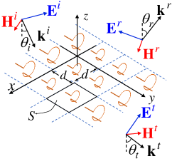
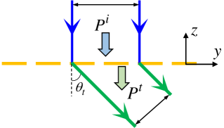
Let us consider a general metasurface that perfectly refracts an incident plane wave with incoming angle to a plane wave with a desired refraction angle , and converts the incident field polarization to a favorable one in the refracted field [see Fig. 1].
(a) (b)
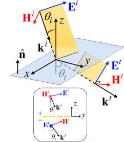
To elaborate the concepts in a simple manner, let us now make our analysis more specific and consider an incident plane wave with a transverse magnetic (TM with respect to ) polarization which is going to be refracted as a transverse electric (TE) polarized plane wave as shown in the subset of the Fig. 1(b). In this example the polarization of the refracted wave is hence rotated by with respect to that of the incident wave. Next, assuming time a harmonic wave with time dependence which travels downward, i.e., in the direction [see Fig. 1(b)], the electric field vector of the incident wave reads and that of the refracted wave reads . Here, , , and are the unit vectors in Cartesian coordinates, whereas and are accordingly the position variables. Moreover, is the free-space wave number, and are the electric field amplitudes of the incident and refracted waves, respectively, and accounts for a possible phase shift between the incident and refracted waves upon crossing the metasurface. The tangential electric and magnetic fields (the subscript denotes the tangential component with respect to the metasurface plane) at the boundary of the metasurface, on both the upper and the lower sides, assuming the metasurface is located on the plane, read
| (1) | ||||
| (2) | ||||
respectively. Here, “” and “” subscripts refer to the tangential fields at the upper () and lower () metasurface boundaries, respectively. Furthermore is the intrinsic wave impedance of the free space, and is the unit vector normal to the metasurface plane in the direction [see Fig.1(b)]. From Eq. (1), the phase of the transmission coefficient reads
| (3) |
which is obviously not uniform over the surface since and indeed it varies linearly with . (Other nonlinear variation may be required for other applications, e.g., focusing Khorasaninejad et al. (2015); Veysi et al. (2015).)
In the next step, we write the boundary conditions which connect the jump of tangential fields on both sides of the metasurface to the induced equivalent electric and magnetic surface polarization densities as Albooyeh et al. (2016, 2017a, 2017b)
| (4) | |||||
| (5) |
where is the angular frequency. Therefore, by plugging Eqs. (1), (2), and (3) into Eqs. (4) and (5), the required electric and magnetic equivalent surface polarization densities for the proposed field manipulation, respectively, read
| (6) | |||||
| (7) |
Here, the TM to TE polarized wave transmission coefficient , and by neglecting losses it is approximated as (see Appendix A for a proof)
| (8) |
where we consider and . Note that the transmission coefficient here is defined with respect to the transverse component of the electric field in the two half spaces, thus, can be larger than unity for an oblique incident or transmission angle, without contradicting the power conservation law.
II.1 Illustrative example
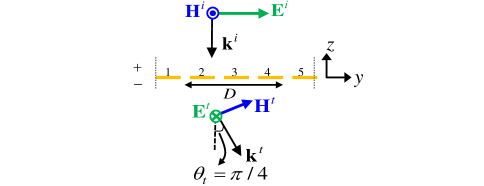
Let us now consider a specific example where and and with each unit cell having the dimension along and along axes as shown in Fig. 2(a). Figure 2(b) and (c) show the required electric and magnetic equivalent polarization densities described by Eqs. (6) and (7) in a unit cell (supercell) for such a metasurface with the mentioned characteristic, i.e., and .
(a)
(b) (c)
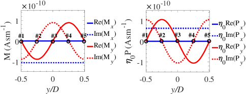
The obtained equivalent polarization surface densities are continuous, uniform in the direction, and periodic in the direction (with period ). However, in general a metasurface is practically composed of discrete elements that mimic such continuous polarization densities. In order to realize a practical design with discrete elements, we take a finite number of sampling points (here five equi-distance points, ) in direction within each supercell to sample the desired continuous equivalent polarization densities given in Fig. 2(b), (c). To demonstrate how the discretization procedure affects the performance of the design we substitute the equivalent polarization densities with electric and magnetic point sources with equivalent magnitudes and phases as sampled at these five sampling points. By implementing the electric and magnetic point sources which mimic the required continuous equivalent polarization densities, we plot the simulation results (using the finite element method implemented in COMSOL multiphysics COM ) of the electric field distribution: the -component of the incident electric field and the -component of the refracted field, in Fig. 3.
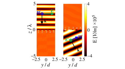
It is clear from the field distribution maps that the power is perfectly refracted by and rotated by , and moreover, as expected the energy density of the refracted wave is lower than the incident one since the total power of the refracted wave is imposed to be equal to the incident power (see the Appendix A for more discussion about energy and power densities). There is no reflection as it can be observed by the lack of any standing wave.
II.2 Possible physical topologies
The result of the previous section indicates the required polarization densities without any discussion about a feasible realization. In order to understand possible topologies for the realization of a metasurface that acquires the proposed equivalent polarization densities, it is helpful to understand what kinds of scatterers (elements or inclusions) are able to create such polarization densities. Considering inclusion realizations that are well approximated by dipole moments, the electric and magnetic polarization densities so far described are realized by using electric and magnetic equivalent dipole polarizations per unit cell where is the unit cell area (see Figure 1(a)). One practical tool is to study the relation between the fields and the equivalent dipole polarizations per unit cell, i.e., the constitutive relations. Indeed, the tangential components of the equivalent dipole polarization densities and and the tangential incident field components and are related through tangential components of the collective polarizabilities , , , and of the metasurface unit cells via constitutive relations Albooyeh et al. (2016); Serdiukov et al. (2001); Hanifeh and Capolino
| (9) | |||
| (10) |
In the above equations, , , , and are collective electric, magnetoelectric, electromagnetic, and magnetic polarizability dyadics in the metasurface plane, relating the incident field to the electric and magnetic dipoles. The word collective means that the polarizability accounts also for the coupling with all the dipoles in the other unit cells of the array Albooyeh et al. (2016); Serdiukov et al. (2001); Albooyeh et al. (2018). Each polarization dyad has four components , where in Cartesian coordinates, i.e., in terms of matrix representation is given by
| (11) |
Note that in the general case polarizability dyadics have nine components, however, for our analysis it is enough to consider only tangential components (see Ref. Albooyeh et al. (2017a, b) for a more elaborated discussion). Next, by plugging the fields from Eqs. (1) and (2) into Eqs. (9) and (10), the equivalent dipole polarizations in term of polarizability components and the incident field read
Based on the above equations, there is obviously not a unique scatterer’s topology to deliver the desired performance since the above are four scalar complex-value equations with 8 complex-value unknown polarizability components (four in each polarizability dyad, however, the selected polarizations in this particular case imply that only eight dyad entrees need to be determined). Nevertheless, among all possible solutions, both electric and magnetic polarizations must be simultaneously nonzero, which this limits the number of possible solutions. Moreover, in the following we suppress the cross-components of the polarizabilities (i.e, ) to narrow down the possible sets of topologies. As a result, the remaining polarizability components imply that the metasurface constitutive inclusions must be chiral since we require that or , for reciprocal lossy and lossless inclusions. By using Eqs. (6) and (7) in Eqs. (II.2) and (II.2) the collective polarizabilities for the proposed chiral metasurface are
| (14) | |||||
In the next section we propose a physical element that exhibits these polarizability components, i.e., the desired equivalent dipole polarizations, and hence, the required equivalent surface polarization densities under the given illumination.
III PHYSICAL REALIZATION
In this section, we first propose a unit cell design that perfectly rotates the polarization of the incoming wave at a normal incidence by . Hence, in the first step, we do not generate plane wave deflection. This latter feature will be realized as a second step by applying the designed unit cell of this first step and constructing a gradient metasurface, to achieve a perfect deflection of a normal incident wave to a refracted wave.
III.1 Unit cell design for polarization rotation
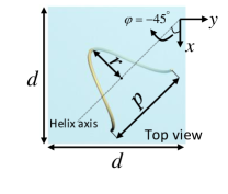
It is well-known that a helical wire particle if excited properly may acquire the polarizabilities described by Eqs. (14) (see Ref. Tretyakov et al. (1996); Fernandez-Corbaton et al. ). Here we use helices with axes belonging to the transverse metasurface plane since we are interested in inducing transverse electric and magnetic dipoles. To optimize the performance of a chiral particle Semchenko et al. introduced optimal helices in Ref. Semchenko et al. (2009) (i.e., helices with equal electric, magnetic, and magneto-electric polarizabilities which means ) which we use here as a part of the design. Such an inclusion provides a maximum cross-polarized transmission when implemented as the building block of a metasurface. The basic building block of a metasurface unit cell is a single optimal helix shown in Fig. 4(a). In particular we consider a single helix made of one turn. The structural parameters i.e., helices radius , helix pitch , unit cell period of the designed helices are illustrated in Fig. 4(a). Moreover the helix axis is oriented along the direction as shown in Fig. 4(a), and the metal is assumed to be a perfect conductor with radius .
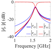
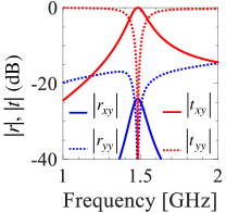
The co-polarized (i.e., along the same direction as the incident electric field) and cross-polarized (i.e., orthogonal to the direction of the incident electric field) field components that defined the reflection and transmission coefficients of a metasurface composed of the unit cell with single helix in Fig. 4(a) are shown in Fig. 4(b). The subscripts and refer to co and cross polarization components, respectively, in a linear polarization basis with the incident electric polarization oriented along the direction. As stated earlier, in the first step we seek a metasurface that is able to perfectly refract the normal incident plane with rotation of the polarization with respect to that of the incident wave, without generating any angular deflection, i.e., the transmitted wave is propagating along the normal direction (the direction). In terms of reflection/transmission coefficients, it means that
| (15) | |||||
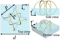
As it is clear from Fig. 4(b), such a design although provides a maximum possible cross-polarized transmission with individual single-turn helix as unit cell, it does not grant perfect transmission of all the incident power to the desired rotated polarization (see that ). Indeed, the incident power is approximately shared evenly between all components of the reflection and transmission spectra at the desired frequency (here around ), hence Eqs. (15) are not satisfied. However, when we increase the number of helices in a unit cell with a proper orientation as mentioned in Ref. Asadchy et al. (2015), i.e., four helices which are rotated by 90 degrees around the axis with respect to each other, then, remarkably, a reflectionless surface can be achieved. Nevertheless, the design in Ref. Asadchy et al. (2015) has a unit cell size that exceeds the operational wavelength, hence it is not a practical design for metasurfaces with incident (refracted) angles rather than normal. Therefore, here we use four interlaced helices in a single unit cell to be sure the unit cell size is subwavelength, a feature that is useful for the implementation of a gradient metasurface which generates a transmitted wave with a deflection, discussed in the next subsection. Figure 4(c) shows the configuration of the four interlaced helices in each unit cell that provide a fully transmittive (i.e., reflectionless) metasurface which perfectly rotates the polarization of the normal incoming wave by . This unit cell is composed of four identical co-centered helices in which their axes lie on the -plane and they are rotated by 90 degrees around the axis. The orientation, spatial position, and structural parameters of the designed helices are illustrated in Figure 4(c), where the structural parameters for each helix are the same as those for the single-helix unit cell in Fig. 4(a). Note that the helices in this design have no electrical connection. A periodic array composed of an infinite number of such chiral unit cells with where is the plane wave’s wavelength shows a perfect to polarization rotation at the frequency of as shown in Fig. 4(d), since the reflection and transmission coefficients of such a metasurface satisfy Eqs. (15). Deduced from this figure, the incident wave with its electric field polarization along is perfectly transmitted into a transmitted wave with electric field polarization along , propagating in the lower half space. It is obvious from this Figure that at the both the - and -polarized reflected waves are negligible.
(a) (b)
(c) (d)
III.2 Supercell design for wavefront deflection
In this section we use a modulation of the metasurface parameters that based on the generalized Snell’s law leads to the transmission phase in Eq. (3). Following this approach, the shape of the wavefront refracted by the array relies on the gradual increase of the transmission phase along the supercell constitutive elements Yu et al. (2011); Veysi et al. (2015); Khorasaninejad et al. (2015); Estakhri and Alu (2016); Wong et al. (2016). Such gradual phase increase along the metasurface is provided by suitably engineering each constitutive inclusion in the so called “supercell”, and since the phase variation is along the direction, the supercell is defined by modulating a few unit cells along the direction, while it has the dimension of a single unit cell in the direction. According to the example in the previous section and Eq. (3), considering a normal incidence, a required transmission angle deflection, and assuming without loss of generality, the transmission phase shall increase linearly in the direction as
| (16) |
This required transmission phase is a continuous function of position along the surface. However, as discussed before, for a practical realization the continuous distribution of electric and magnetic polarization densities is realized in a discretized fashion, i.e., by a finite number of electric and magnetic induced dipole moments in each supercell. The desired phase distribution across the metasurface is obtained by meticulously optimizing the dimensions of the four interlaced helices in a few unit cells that make the supercell. In the present realization the supercell is divided into five unit cells as shown in the figure below Table 1, that shows the optimized dimensions of the helices in each of the five unit cells. The required transmission phases at the location of the five different unit cells are obtained from Eq. (16) where where . Note that all the four helices in each individual unit cell are identical.
| # 1 | # 2 | # 3 | # 4 | # 5 | |
|---|---|---|---|---|---|
![[Uncaptioned image]](/html/1905.04439/assets/x10.png)
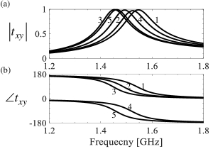
Therefore the metasurface is made of an array of supercells with dimension along the direction and along the direction. The design of the supercell elements is done as follows: First, we design five distinct metasurfaces, each one made of a periodic array of each unit cells in table 1, with period in both and directions. The full-wave simulation based on the finite element method is based on periodic boundary conditions. Therefore, a single unit cell of dimension is simulated for normal plane wave incidence, and the transmitted phase is evaluated for each type of these five metasurfaces. For each metasurface, dimensions are optimized to provide a perfect cross-polarized transmittance (this is possible based on the results of the previous subsection) and transmission phase given in Table 1. The resulting magnitude and phase of the - to -polarized wave transmission coefficient is depicted in Fig. 5 for the five different metasurfaces, each one based on a different inclusion’s dimensions given in Table 1.
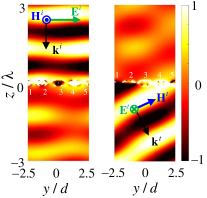
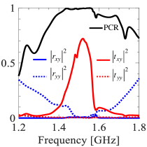
Next, the gradient metasurface to provide an angular deflection of is made of a periodic arrangement of supercells with dimension along the direction and along the direction. As a result the designed metasurface has a desired periodic phase distribution along the direction (see Eq. (16)) and a uniform phase distribution along the direction. The field distribution in proximity of the engineered gradient metasurface, excited with a normally incident plane wave polarized along the direction, is illustrated in Fig. 6(a) where the field distribution is calculated with a full wave simulation based on the finite element method. The distribution of the -polarization (left) and the -polarization (right) of the electric field are plotted in Fig. 6(a) at the frequency of . In this simulation based on the finite element method, periodic boundaries are chosen to mimic the infinite extension of the metasurface along both and directions, i.e., modeling a periodic supercell of dimensions . In this combined design we account for losses, i.e., helices are made of copper and are embedded in a foam (FR 3703 from General Plastics) with dielectric constant of 1.06 and loss tangent of 0.0004 as in Fig. 4. As it is clear from Fig. 6, the gradient metasurface rotates the polarization of the incident wave by and refracts it into . The result in Fig. 6(a) does not show the perfect polarization rotation and deflection as the ideal case in Fig. 3 because in the actual design of the gradient metasurface, we have used the concept of local periodicity in designing the five unit cells of the supercell, which is a standard approximation in metasurface and reflectarray design Huang and Encinar ; Veysi et al. (2015) but it is not fully accurate. As a measure of the metasurface performance we define the polarization conversion ratio (PCR) in transmission as
| (17) |
where and are the magnitude of - to -polarized (cross-pol component) and - to -polarized (co-pol component) transmission coefficients, respectively. Fig. 6(b) shows the PCR versus frequency, as well as the - to -polarized reflectance and transmittance of a -polarized incident wave. As it is obvious from this figure we obtain a perfect () polarization conversion and power transmission into the deflected wave with the engineered metasurface. To the best of our knowledge, this is an unprecedented result, i.e., this is the first design of a metasurface that provides simultaneous deflection and polarization rotation of the incoming wavefront with such a high efficiency.
(a)
(b)
IV Conclusion
In the framework of gradient metasurfaces we have shown that in principle, using chirality, it is possible to obtain perfect polarization rotation of the electromagnetic wavefront with concurrent full transmission into a desired deflected direction. The chirality characteristic of a metasurface serves for polarization rotation of the transmitted plane wave with respect to the incident one, whereas the gradient property (i.e., the spatial dispersion) of the metasurface grants for the wavefront deflection. Furthermore, we have demonstrated a possible physical realization of the proposed device by engineering a proper metasurface unit cell inclusion that realizes the aforementioned combined functionalities. Our full wave simulation results demonstrate high transmission power efficiency of at an angle of by using only one single layer of inclusions (i.e., a single metasurface) which is accompanied by a perfect polarization rotation. Despite the fact that the results are shown for a specific illustrative case, the method outlined in this paper is very general and can be used for conceiving metasurfaces that deflect wavefronts at any angle with arbitrary polarization conversion and with (in theory) perfect transmittance.
In short, in a single metasurface we have combined two interesting functionalities, i.e., a wave refraction at a given angle and a polarization rotation, with very high efficiency and subwavelength thickness, by using chiral metasurface inclusions.
V Acknowledgment
The authors would like to thank DS SIMULIA for providing CST Studio Suite that was instrumental in this study. Also, the authors acknowledge support from the W. M. Keck Foundation, USA.
Appendix A Energy densities of the incident and refracted waves, power balance relation, and transmission coefficient for perfect power transmission and polarization conversion
The characteristic of the proposed fully-transmissive metasurface is such that the wave passes through it without changing its total time-average power (when the metasurface is lossless) and the metasurface changes the polarization and the direction of the transmitted wavefront with respect to the incident one. Therefore, the total incident and refracted powers crossing the metasurface along the ray tube in Fig. 7 are equal. Under such condition, the total time-average incident and transmitted field energy densities are required to satisfy
| (18) |
Therefore in this scenario, since the total time-average incident and transmitted energy densities, and , are different, the wave intensity changes when passing through the fully-transmissive metasurface. This can be described also in the following manner, by observing the power crossing a plane with constant , right above and below the metsurface. Of course such powers are equal to each other when considering a lossless metasurface, which implies the conservation of the normal component of the Poynting vector from above to below the metasurface, i.e.,
| (19) |
| (20) |
where and , then
| (21) |
for a reflectionless surface. Thus for normal incidence, which is larger than unity for an oblique transmission angle, without contradicting the power conservation law.
References
- Albooyeh et al. (2016) M. Albooyeh, S. Tretyakov, and C. Simovski, Annalen der Physik 528, 721 (2016).
- Achouri et al. (2015) K. Achouri, M. A. Salem, and C. Caloz, IEEE Transactions on Antennas and Propagation 63, 2977 (2015).
- Asadchy et al. (2016) V. S. Asadchy, M. Albooyeh, S. N. Tcvetkova, A. Diaz-Rubio, Y. Ra’di, and S. A. Tretyakov, Physical Review B 94, 075142 (2016).
- Chen et al. (2016) H. T. Chen, A. J. Taylor, and N. Yu, Reports on Progress in Physics 79, 076401 (2016).
- Cheng et al. (2013) Y. Cheng, Y. Nie, X. Wang, and R. Gong, Applied Physics A 111, 209 (2013).
- Faniayeu et al. (2017) I. Faniayeu, S. Khakhomov, I. Semchenko, and V. Mizeikis, Applied Physics Letters 111, 111108 (2017).
- Markovich et al. (2013) D. L. Markovich, A. Andryieuski, M. Zalkovskij, R. Malureanu, and A. V. Lavrinenko, Applied Physics B 112, 143 (2013).
- Menzel et al. (2010) C. Menzel, C. Helgert, C. Rockstuhl, E.-B. Kley, A. Tunnermann, T. Pertsch, and F. Lederer, Physical Review Letters 104, 253902 (2010).
- Pfeiffer and Grbic (2014) C. Pfeiffer and A. Grbic, Physical Review Applied 2, 044011 (2014).
- Pfeiffer et al. (2016) C. Pfeiffer, C. Zhang, V. Ray, L. J. Guo, and A. Grbic, Optica 3, 427 (2016).
- Safari et al. (2017) M. Safari, A. Abdolali, H. Kazemi, M. Albooyeh, M. Veysi, and F. Capolino, in 2017 IEEE International Symposium on Antennas and Propagation USNC/URSI National Radio Science Meeting (2017) pp. 1499–1500.
- Vehmas et al. (2013) J. Vehmas, Y. Ra’di, A. O. Karilainen, and S. A. Tretyakov, IEEE Transactions on Antennas and Propagation 61, 3747 (2013).
- Xiao et al. (2015) Z. Xiao, D. Liu, X. Ma, and Z. Wang, Optics Express 23, 7053 (2015).
- Zheng et al. (2018) Q. Zheng, C. Guo, H. Li, and J. Ding, Journal of Electromagnetic Waves and Applications 32, 265 (2018).
- Zhu et al. (2017) Z. Zhu, H. Liu, Z. Jiang, T. Lv, C. Guan, and J. Shi, Journal of Applied Physics 122, 215101 (2017).
- Capolino et al. (2013) F. Capolino, A. Vallecchi, and M. Albani, IEEE Transactions on Antennas and Propagation 61, 852 (2013).
- Glybovski et al. (2016) S. B. Glybovski, S. A. Tretyakov, P. A. Belov, Y. S. Kivshar, and C. R. Simovski, Physics Reports 634, 1 (2016).
- Tretyakov (2015) S. A. Tretyakov, Philosophical Transactions of the Royal Society of London A: Mathematical, Physical and Engineering Sciences 373 (2015).
- Wong et al. (2016) J. P. S. Wong, A. Epstein, and G. V. Eleftheriades, IEEE Antennas and Wireless Propagation Letters 15, 1293 (2016).
- (20) H. Kazemi, M. Albooyeh, and F. Capolino, in URSI EM Theory Symposium, EMTS 2019, San Diego, CA 27-31 May 2019 (URSI).
- Mohammadi Estakhri and Alù (2016) N. Mohammadi Estakhri and A. Alù, Phys. Rev. X 6, 041008 (2016).
- Alaee et al. (2016) R. Alaee, M. Albooyeh, S. Tretyakov, and C. Rockstuhl, Opt. Lett. 41, 4099 (2016).
- Albooyeh et al. (2015) M. Albooyeh, R. Alaee, C. Rockstuhl, and C. Simovski, Phys. Rev. B 91, 195304 (2015).
- Guo et al. (2017) Y. Guo, M. Xiao, and S. Fan, Physical Review Letters 119, 167401 (2017).
- Rajaei et al. (2019) M. Rajaei, J. Zeng, M. Albooyeh, M. Kamandi, M. Hanifeh, F. Capolino, and H. K. Wickramasinghe, ACS Photonics (2019).
- Yu et al. (2011) N. Yu, P. Genevet, M. A. Kats, F. Aieta, J.-P. Tetienne, F. Capasso, and Z. Gaburro, Science 334, 333 (2011).
- Shalaev et al. (2015) M. I. Shalaev, J. Sun, A. Tsukernik, A. Pandey, K. Nikolskiy, and N. M. Litchinitser, Nano Letters 15, 6261 (2015).
- Monticone et al. (2013) F. Monticone, N. M. Estakhri, and A. Alù, Phys. Rev. Lett. 110, 203903 (2013).
- Pfeiffer and Grbic (2013) C. Pfeiffer and A. Grbic, IEEE Transactions on Microwave Theory and Techniques 61, 4407 (2013).
- Veysi et al. (2015) M. Veysi, C. Guclu, O. Boyraz, and F. Capolino, JOSA B 32, 318 (2015).
- Elsakka et al. (2016) A. A. Elsakka, V. S. Asadchy, I. A. Faniayeu, S. N. Tcvetkova, and S. A. Tretyakov, IEEE Transactions on Antennas and Propagation 64, 4266 (2016).
- Chen et al. (2017) M. Chen, E. Abdo-Sanchez, A. Epstein, and G. V. Eleftheriades, in 2017 XXXIInd General Assembly and Scientific Symposium of the International Union of Radio Science (URSI GASS) (2017) pp. 1–4.
- Asadchy et al. (2017) V. S. Asadchy, A. Díaz-Rubio, S. N. Tcvetkova, D.-H. Kwon, A. Elsakka, M. Albooyeh, and S. A. Tretyakov, Phys. Rev. X 7, 031046 (2017).
- Emani et al. (2017) N. K. Emani, E. Khaidarov, R. Paniagua-Dominguez, Y. H. Fu, V. Valuckas, S. Lu, X. Zhang, S. T. Tan, H. V. Demir, and A. I. Kuznetsov, Applied Physics Letters 111, 221101 (2017).
- Wong et al. (2018) A. M. H. Wong, P. Christian, and G. V. Eleftheriades, IEEE Transactions on Antennas and Propagation 66, 2892 (2018).
- Rabinovich and Epstein (2018) O. Rabinovich and A. Epstein, IEEE Transactions on Antennas and Propagation (2018).
- Yu et al. (2012) N. Yu, F. Aieta, P. Genevet, M. A. Kats, Z. Gaburro, and F. Capasso, Nano Letters 12, 6328 (2012).
- Wu et al. (2014) C. Wu, N. Arju, G. Kelp, J. A. Fan, J. Dominguez, E. Gonzales, E. Tutuc, I. Brener, and G. Shvets, Nature communications 5, 3892 (2014).
- Selvanayagam and Eleftheriades (2016) M. Selvanayagam and G. V. Eleftheriades, IEEE Transactions on Microwave Theory and Techniques 64, 414 (2016).
- Li et al. (2016) J. Li, P. Yu, H. Cheng, W. Liu, Z. Li, B. Xie, S. Chen, and J. Tian, Advanced Optical Materials 4, 91 (2016).
- Kim and Eleftheriades (2016) M. Kim and G. V. Eleftheriades, Optics letters 41, 4831 (2016).
- Jia et al. (2016) Y. Jia, Y. Liu, Y. J. Guo, K. Li, and S. X. Gong, IEEE Transactions on Antennas and Propagation 64, 179 (2016).
- Farmahini-Farahani and Mosallaei (2013) M. Farmahini-Farahani and H. Mosallaei, Optics Letters 38, 462 (2013).
- Aieta et al. (2012) F. Aieta, P. Genevet, N. Yu, M. A. Kats, Z. Gaburro, and F. Capasso, Nano Letters 12, 1702 (2012).
- Khorasaninejad et al. (2015) M. Khorasaninejad, F. Aieta, P. Kanhaiya, M. A. Kats, P. Genevet, D. Rousso, and F. Capasso, Nano letters 15, 5358 (2015).
- Albooyeh et al. (2017a) M. Albooyeh, H. Kazemi, F. Capolino, D. H. Kwon, and S. A. Tretyakov, in 2017 IEEE International Symposium on Antennas and Propagation USNC/URSI National Radio Science Meeting (2017) pp. 1707–1708.
- Albooyeh et al. (2017b) M. Albooyeh, D.-H. Kwon, F. Capolino, and S. A. Tretyakov, Phys. Rev. B 95, 115435 (2017b).
- (48) “Comsol multiphysics reference manual, version 5.3, comsol, inc, www.comsol.com,” .
- Serdiukov et al. (2001) A. Serdiukov, I. Semchenko, S. Tertyakov, and A. Sihvola, Electromagnetics of bi-anisotropic materials-Theory and Application, Vol. 11 (Gordon and Breach science publishers, 2001).
- (50) M. Hanifeh and F. Capolino, Eprint ArXiv1905.03387 (2019) .
- Albooyeh et al. (2018) M. Albooyeh, V. Asadchy, J. Zeng, H. Kazemi, and F. Capolino, arXiv preprint arXiv:1811.04176 (2018).
- Tretyakov et al. (1996) S. A. Tretyakov, F. Mariotte, C. R. Simovski, T. G. Kharina, and J. P. Heliot, IEEE Transactions on Antennas and Propagation 44, 1006 (1996).
- (53) I. Fernandez-Corbaton, C. Rockstuhl, P. Ziemke, P. Gumbsch, A. Albiez, R. Schwaiger, T. Frenzel, M. Kadic, and M. Wegener, Advanced Materials , 1807742.
- Semchenko et al. (2009) I. V. Semchenko, S. A. Khakhomov, and A. L. Samofalov, Russian Physics Journal 52, 472 (2009).
- Asadchy et al. (2015) V. S. Asadchy, I. A. Faniayeu, Y. Ra’di, S. A. Khakhomov, I. V. Semchenko, and S. A. Tretyakov, Phys. Rev. X 5, 031005 (2015).
- Estakhri and Alu (2016) N. M. Estakhri and A. Alu, JOSA B 33, A21 (2016).
- (57) J. Huang and J. A. Encinar, Reflectarray Antennas, 1st ed. (Wiley-IEEE Press).