Optimization-based approach to the calibration of mesoscale mechanical models for carbon nanotube systems
Abstract
A new mesoscale mechanical model, describing elastic interactions in carbon nanotubes (CNT) and other nanofilaments, is proposed. Functional form of the developed model is based on enhanced vector model (EVM) that describes basic types of bond deformations: tension, torsion, bending and shear. Calibration of bond stiffnesses is performed by adjusting EVM parameters to reproduce both CNT’s deformation energies and shape observed in a full-atomistic simulation. The parameters obtained are compared with the ones obtained from Euler-Bernoulli beam theory considerations. It is found that after certain critical length of a tested CNT specimen its stiffness parameters become length-independent and can be used in mesoscale simulations of CNTs of arbitrary length.
1 Introduction
Since their discovery [1], carbon nanotubes (CNT) became a core component for a great variety of technologies, ranging from reinforced composites [2] to wearable electronics devices [3]. 111Although in the following we limit our discussion to CNTs, our results are directly applicable to other types of nanofilaments, such as boron-nitride nanotubes and zinc oxide nanotubes that are actively studied in a context of numerous possible applications. Further technological development urges the design of predictive models that could simulate the behaviour of CNT-based materials. Although ab-initio and atomistic modelling give deep insight into underlying physics and mechanics of CNTs, many systems of scientific and engineering significance (e.g. CNT films, ropes, mats and forests) remain computationally prohibitive. In order to simulate such systems, one has to use mesoscale/coarse-grained (CG) simulation approaches.
In order to provide an efficient and accurate description of the mechanics and physics of CNT systems, a number of different mesoscale models were developed. One of the first was bead and spring (BS) model [4], which represents a CNT as the chain of point masses (beads). Within this approach a "spring" potential is used to describe covalent interactions within a CNT, and a coarse-grained Lennard-Jones potential is employed to model dispersive interactions between neighbouring CNTs. Such model can easily be implemented in existing molecular dynamics codes, and it reasonably well reproduces the mechanical properties of a single CNT. However, this modeling approach has a list of critical shortcomings that make it inapplicable in many relavant situations. The first of them is the absence of torsional degrees of freedom that produces unrealistic behaviour of CNT assemblies under certain loadings. The second problem is the artificial corrugation of van der Waals interaction potential, emerging due to representation of a cylindrical CNT segment with a point mass. Such an artefact leads to the fact that BS model can not reproduce realistic self-assembly processes in CNT systems due to vdW adhesion, and grossly overestimates yield strength of CNT materials (see the discussion in []).
Another CG approach for modelling CNT, mesoscopic force-field (MFF), is proposed by Zhigilei et al. [5]. In this framework, CNT dynamics also described in terms of nodal point masses. Although in the seminal work [5] torsion term is present in the Lagrangian of the conceptual CNT elasticity model, the authors later neglect it and coarse-grain CNT description to the level of a chain of point masses. In contrast to BS, further development of the MFF approach with inter-tube interactions [6] allowed to simulate formation of large bundles composed of approximately 50 – 100 CNTs, which is qualitatively consistent with experiments [7].
Torsion part of CNT’s potential energy is consistently taken into account in the study [8]. Proposed CG model is based on parallel-bond (PB) representation of the potential energy [9] and represents nanotube as a chain of rigid bodies with both positions and orientations. This allows to describe not only bending but also torsion of a single CNT, which is important for modelling ropes and fibers woven of individual CNTs [10].
A common issue of all listed approaches which has not been addressed so far is the rigorous and accurate procedure of coarse-grained model‘s calibration based on molecular level simulations. In all the described approaches [4, 5, 8], the model for nanotube stiffness utilises linear elastic beam theory. Clearly, such "top-down" approach involves an unsupported assumption of the beam‘s theory validity on the microscopic level and can lead to significant model’s inaccuracy. Although in work [5] deformation energies for the calibration were calculated on atomistic level, comparison between the shape of mesoscale and full-atomic CNTs were not performed.
In this work we present a new approach to the construction of a mesoscale mechanical model for CNT. It is based on the concurrent energy minimization in the coarse and fine models with subsequent matching potential energies of the system. This approach is employed for calibration of recently developed enhanced vector model (EVM) [11]. Unlike previously used parallel bond model, it provides precise energy conservation in zero-damping simulation, and can be easily generalised to capture nonlinear effects and bond fracture. Our approach completely relies on atomistic-level computations, none of the results from linear elastic beam theory are used in the calibration procedure.
Our results allowed to improve calibration accuracy for the recently developed mesoscale distinct element method (MDEM) [12] for large-scale dynamic modelling of carbon nanotube assemblies. The proposed framework can also be used in more general context for calibration and verification of CG models for different types of nanostructures.
2 Methods
2.1 Mesoscale model
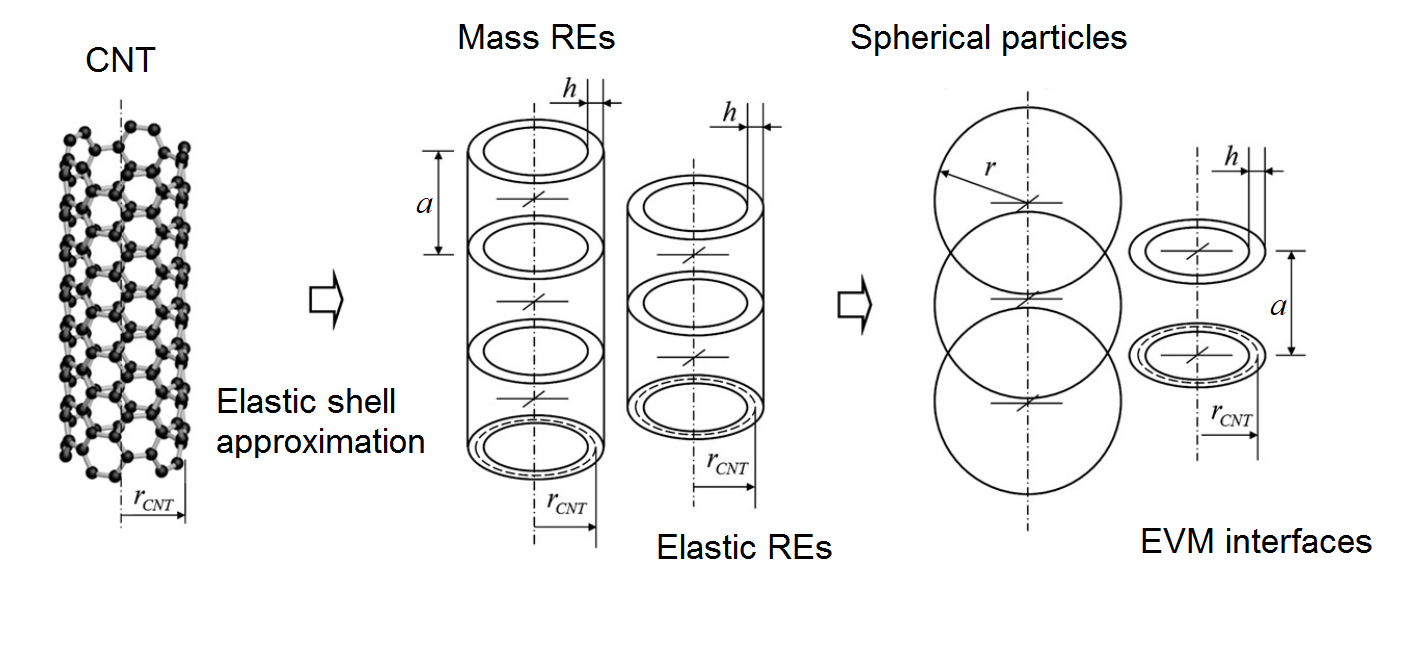
Within our mesoscale model, a CNT is partitioned into a chain of identical hollow cylindrical segments, representing inertial and elastic properties of the corresponding groups of carbon atoms (fig. 1). Each segment has a length of equal to two CNT radii: .
The inertial properties of the segment are represented with the rigid spherical particle. Its radius is chosen to match the moment of inertia of the segment with respect to CNT axis. The corresponding inertial radius is given by .
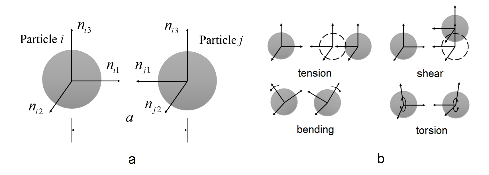
The elastic properties of a segment are described by EVM [11, 13]. It is based on a binding potential, describing the behaviour of an elastic material linking two rigid bodies. The formulation provides straightforward generalisation on the case of large strains and accounts for a bending-twisting geometric coupling. Consider two equal-sized spherical particles and with equilibrium separation distance and orientations described by orthogonal vectors (fig. 2 (a) , , , ).
The potential energy in EVM is given by:
| (1) |
Here is a radius-vector connecting centers of bonded particles, .
2.2 Atomistic model
Atomistic simulation is used to define the difference ( ) between energies in unstained and deformed states. This value is then utilized in calibration of mesoscale model parameters as described below.
Considered atomistic configurations of CNT contain from to carbon atoms. Interactions between neighbouring atoms are described by AIREBO (Adaptive Intermolecular Reactive Empirical Bond Order) [14] potential. HFTN (Hessian Free Truncated Newton) optimization algorithm [15] is used for structure relaxation. Non-periodic boundary conditions are imposed.
In order to provide one-to-one correspondence between atomistic and coarse-grained models, we unite carbon atoms into groups corresponding to the segments in a mesoscale model. During our simulations, we track the averaged group positions, that are then used in comparison of the shapes obtained from atomistic and mesoscale models.
2.2.1 Calibration
EVM potential (1) allows to consider an arbitrary deformation as a combination of four elementary modes – tension, shearing, bending and torsion. Hence, EVM calibration on the results of atomistic simulation can be carried out by four concurrent elementary tests in CG and full-atomistic models and direct matching of deformation energies in all cases.
Such a strategy is described with the following optimization problem:
| (2) |
Here is an error function, – energy of deformation in atomistic and CG models.
Calibration procedure can be described as a three-stage process:
(I) On the first stage, the atomistic simulation is used to compute a set of deformation energies and positions for different types of loading.
(II) The next step is a static energy minimization of CG CNT configuration. At this stage the parameters are fixed and only coarse-grained degrees of freedom (positions and rotations) are varied to obtain a minimum of potential energy. As a result one can obtain a certain CNT configuration which is identical to the solution of static equilibrium equations for CNT. Minimization is performed by basin hopping optimization technique [16].
(III) The last stage is adjusting coefficients while solving problem (2) utilizing differential evolution [17] algorithm.
As the result of this process, we obtain the CG potential that reproduces both deformation shapes and energies observed in full atomistic simulation.
3 Results
In this section we demonstrate the application of the proposed calibration procedure to single-walled CNTs of various lengths and chiralities. We first obtain the initial guess for CG model parameters from linear Euler-Bernoulli beam theory. Then we follow the calibration algorithm described above. The coefficients (tension) and (torsion) of EVM model are obtained from decoupled deformation tests, while (shear) and (bending) stiffnesses are evaluated from coupled deformations. The pipeline is demonstrated in details for (10,10) CNT, the results for different types of CNTs are briefly presented in the last subsection.
3.1 Initial guess
In the first approximation the CG parameters are estimated using Euler-Bernoulli beam theory [18]:
| (3) |
Here , , and are equilibrium distance between segments, interface cross section area, moment of inertia and polar moment of inertia respectively:
| (4) |
.
Consider the case of (10, 10) CNT which is divided into segments containing approximately 220 carbon atoms. The comparison between segments in full-atomic and mesoscale models are carried out with respect to it‘s length, hence there is no uniform distribution of atoms into segments. Mass and geometry properties of a segment are presented in table 1; Young’s modulus and shear modulus are taken from ab-initio calculations [19].
| 2649 | 13.56 | 3.35 | 142.7 | 3480 | 6960 |
Utilizing this data, one can estimate , , , . Obtained values are used as an initial guess in our optimization-based calibration procedure.
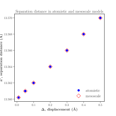
3.2 Tensile stiffness calibration
Consider pure stretching of CNT along the axial vector , which is equivalent to tension of all bonds between segments within considered CNT. In this case the potential (1) can be simplified to:
| (5) |
In order to provide a uniform stretching of all bonds in CNT we displace the last segment/group of atoms in the chain to the distance of at both CG and atomistic models. Then positions of the first and last segment‘s/groups of atoms are fixed so the other segments/atoms change their location during optimization procedure in order to minimize total potential energy. As a result of the energy minimisation all bonds of the CNT are become equally stretched in both models (fig. 3):
3.3 Torsional stiffness calibration
For the case of pure axial torsion the potential (1) can be simplified to:
| (6) |
Torsion test is performed by rotating of the last segment/group of atoms on the angle of along the nanotube axis. Orientation of the first and last segments / group of atoms are then fixed and configuration optimization is performed. As a result, one can obtain a linear distribution of twisting angle along the CNT axis (fig. 4):
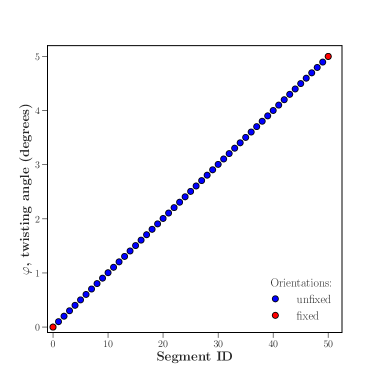
Note that the results of structure optimization for tensile and torsion tests are obvious and follow directly from the balance of force and moment in a chain of interacting segments. We provide them as benchmarks for our calibration technique. The resulting configurations are in perfect agreement with analytical solutions, which verifies the validity of our approach.
The optimization problem (2) is solved with simplified potential (6), as a result we found coefficient to be equal to 1107 eV. Similarly to the stretching case, the obtained value of twisting stiffness does not depend both on deformation value and CNT length (for long enough CNTs), as discussed below.
3.4 Shearing and bending cases
So far we considered only decoupled deformation cases that admitted single-parameter optimization. However, this approach is inapplicable for bending/shear deformation. In this case, the potential (1) will take a form of:
| (7) |
Potential (7) depends both on shear stiffness and bending stiffness which can not be decoupled.
For this case the optimization problem (2) is slightly modified in order to minimize error in potential energy at two bending/shear tests by fitting two stiffness parameters:
| (8) |
Here , are error functions for two independent tests - three-point and similar two-point coupled bending/shearing tests.
In the first case the positions and orientations of two edge segments/group of atoms of a CNT specimens are fixed. Then the N /2 and N / 2 + 1 (two segments are taken in order to conserve symmetry) segments/groups of atoms are displaced in transversal direction to the value of . The optimization process converges to an equilibrium CNT profile (fig. 5, a):
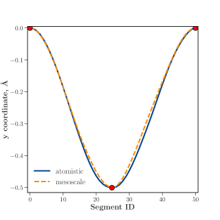
a)
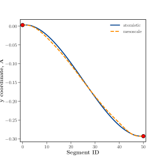
b)
In the second case, the similar test is performed in two point manner: the first segment/group of atoms is fixed, and the last one is displaced on (fig. 5, b)
While solving (8) with the potential (7), one can found for and to be equal to 17100 eV and 3610 eV respectively.
Our concurrent optimization approach leads to the set of stiffness values that are noticeably different from the predictions of beam theory:
| Optimization-based | Euler-Bernoulli | |
|---|---|---|
| 60.1 | 67.6 | |
| 17100 | 19800 | |
| 3610 | 4030 | |
| 1107 | 1400 |
3.5 Other types of CNTs
We performed similar calibrations for two other types of CNTs: (10, 0) "zigzag" CNT‘s and (15,15) "armchair" CNTs.
Table summarizes EVM parameterizations for three different CNT types and segment sizes.
| Segment length, Å | 6.78 | 13.56 | 27.12 |
|---|---|---|---|
| Coefficient | 115.9 | 60.1 | 30.9 |
| Coefficient | 35500 | 17100 | 9300 |
| Coefficient | 10660 | 3610 | 1850 |
| Coefficient | 2228 | 1107 | 592 |
Tables give comparison of initial guess values with optimization results for (10,0) CNTs and (15,15) CNTS.
| Optimization-based | Euler-Bernoulli | |
|---|---|---|
| 41.1 | 28.0 | |
| 5850 | 2700 | |
| 1340 | 550 | |
| 230 | 100 |
| Optimization-based | Euler-Bernoulli | |
| 85.1 | 98.2 | |
| 78100 | 106200 | |
| 17500 | 21650 | |
| 3411.1 | 3950.6 |
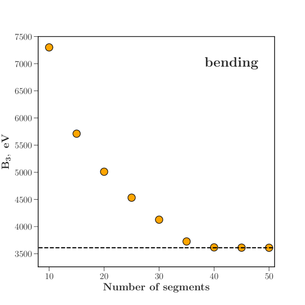
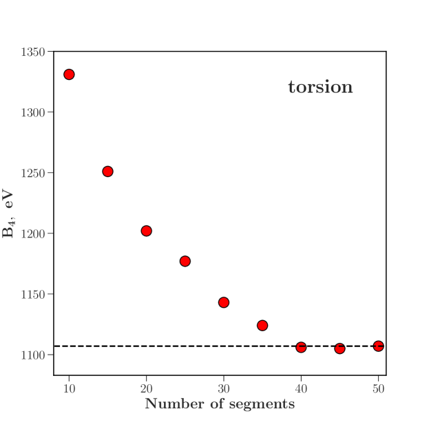
3.6 Size dependence of stiffnesses
Our tests indicate that short CNTs feature significant size dependence of stiffness (fig. 6). However, for long enough CNTs (approximately 50 nm for (10,10) CNTs), this size dependence vanishes, and stiffness calibrations do not depend on the specimen’s size.
![[Uncaptioned image]](/html/1905.04400/assets/x5.png)
a)
![[Uncaptioned image]](/html/1905.04400/assets/x6.png)
b)
c)
d)
4 Conclusions
In this work we have described a systematic "bottom-up" approach to calibration of mesoscale mechanical models for elastic fibrils based on optimization technique. We illustrated our approach by calibrating tension, shear, bending and torsional stiffnesses for CG models of few types of CNTs. It was shown that mesoscopic EVM potential, which was used for elastic interactions, does reproduce fibril’s deformation. Our approach allows to refine the calibrations used in mesoscale modeling of nanofilaments, and can be straightforwardly generalized onto different types of mesoscale structures (e.g ZnO nanobelts).
5 Acknowledgements
The authors gratefully acknowledge the financial support from Russian Science Foundation under grant 17-73-10442.
References
- [1] Sumio Iijima. Helical microtubules of graphitic carbon. nature, 354(6348):56, 1991.
- [2] Amal MK Esawi and Mahmoud M Farag. Carbon nanotube reinforced composites: potential and current challenges. Materials & design, 28(9):2394–2401, 2007.
- [3] Evgenia P Gilshteyn, Daler Amanbaev, Maxim V Silibin, Artem Sysa, Vladislav A Kondrashov, Anton S Anisimov, Tanja Kallio, and Albert G Nasibulin. Flexible self-powered piezo-supercapacitor system for wearable electronics. Nanotechnology, 29(32):325501, 2018.
- [4] Markus J Buehler. Mesoscale modeling of mechanics of carbon nanotubes: self-assembly, self-folding, and fracture. Journal of materials research, 21(11):2855–2869, 2006.
- [5] Leonid V Zhigilei, Chenyu Wei, and Deepak Srivastava. Mesoscopic model for dynamic simulations of carbon nanotubes. Physical review B, 71(16):165417, 2005.
- [6] Alexey N Volkov, Kiril R Simov, and Leonid V Zhigilei. Mesoscopic model for simulation of cnt-based materials. In ASME 2008 International Mechanical Engineering Congress and Exposition, pages 1235–1245. American Society of Mechanical Engineers, 2008.
- [7] Erik K Hobbie, Daneesh O Simien, Jeffrey A Fagan, JiYeon Huh, Jun Y Chung, Steven D Hudson, Jan Obrzut, Jack F Douglas, and Christopher M Stafford. Wrinkling and strain softening in single-wall carbon nanotube membranes. Physical review letters, 104(12):125505, 2010.
- [8] Igor Ostanin, Roberto Ballarini, David Potyondy, and Dumitrica. A distinct element method for large scale simulations of carbon nanotube assemblies.
- [9] David O Potyondy and PA Cundall. A bonded-particle model for rock. International journal of rock mechanics and mining sciences, 41(8):1329–1364, 2004.
- [10] Yuezhou Wang, Igor Ostanin, Cristian Gaidau, and Traian Dumitrica. Twisting carbon nanotube ropes with the mesoscopic distinct element method: Geometry, packing, and nanomechanics. Langmuir, 31(45):12323–12327, 2015.
- [11] Vitaly A Kuzkin and Igor E Asonov. Vector-based model of elastic bonds for simulation of granular solids. Physical review E, 86(5):051301, 2012.
- [12] I. Ostanin, P. Zhilyaev, V. Petrov, T. Dumitrica, S. Eibl, U. Ruede, and V. Kuzkin. Toward large scale modeling of carbon nanotube systems with the mesoscopic distinct element method. Letters on Materials, 3:10, 2018.
- [13] V.A. Kuzkin and A.M. Krivtsov. Enhanced vector-based model for elastic bonds in solids. Letters of Materials, 7:455–458, 2017.
- [14] Steven J Stuart, Alan B Tutein, and Judith A Harrison. A reactive potential for hydrocarbons with intermolecular interactions. The Journal of chemical physics, 112(14):6472–6486, 2000.
- [15] Stephen G Nash. A survey of truncated-newton methods. Journal of computational and applied mathematics, 124(1-2):45–59, 2000.
- [16] Brian Olson, Irina Hashmi, Kevin Molloy, and Amarda Shehu. Basin hopping as a general and versatile optimization framework for the characterization of biological macromolecules. Advances in Artificial Intelligence, 2012:3, 2012.
- [17] Rainer Storn and Kenneth Price. Differential evolution – a simple and efficient heuristic for global optimization over continuous spaces. Journal of Global Optimization, 11(4):341–359, Dec 1997.
- [18] Vitaly A Kuzkin and Igor E Asonov. Vector-based model of elastic bonds for simulation of granular solids. Physical review E, 86(5):051301, 2012.
- [19] Zhang D.B. and Traian Dumitrica. Elasticity of ideal single-walled carbon nanotubes via symmetry-adapted tight-binding objective modeling. Applied Physics Letters, 93(031919), 2008.