Energy Efficient Power and Channel Allocation in Underlay Device to Multi Device Communications
Abstract
In this paper, we optimize the energy efficiency (bits/s/Hz/J) of device-to-multi-device (D2MD) wireless communications. While the device-to-device scenario has been extensively studied to improve the spectral efficiency in cellular networks, the use of multicast communications opens the possibility of reusing the spectrum resources also inside the groups. The optimization problem is formulated as a mixed integer non-linear joint optimization for the power control and allocation of resource blocks (RBs) to each group. Our model explicitly considers resource sharing by letting co-channel transmission over a RB (up to a maximum of transmitters) and/or transmission through different channels in each group. We use an iterative decomposition approach, using first matching theory to find a stable even if sub-optimal channel allocation, to then optimize the transmission power vectors in each group via fractional programming. Additionally, within this framework, both the network energy efficiency and the max-min individual energy efficiency are investigated. We characterize numerically the energy-efficient capacity region, and our results show that the normalized energy efficiency is nearly optimal (above 90 percent of the network capacity) for a wide range of minimum-rate constraints. This performance is better than that of other matching-based techniques previously proposed.
Index Terms:
Optimization, fractional programming, matching theory, D2D multicasting communication, 5G wireless networks.I Introduction
A number of different technological advancements are being considered for realizing the expected capabilities of 5G networks [1], in terms of data volume, throughput and users’ density. These include massive MIMO, mm-wave communications, small cells, content caching and device-to-device (D2D) communications, among others. In particular, D2D is a conceptually simple technique that allows users in close proximity to communicate directly without the intervention of a central entity like a base station (BS) or an access point (AP). This short-range communication mode provides high data rate, low latency, high energy efficiency and increased system capacity. D2D communications can take place in-band or out-band [2], the first type when a D2D-enabled device shares the licensed spectrum with cellular users (underlay communication), the second case if dedicated bandwidth is reserved for D2D devices, which then would form an overlay network. One of the key performance metrics for optimizing the design and operations in cellular networks and for using efficiently the physical resources is the energy efficiency (EE) [3]. Energy efficiency is the normalized data transmission rate (bits per second per hertz) divided by the amount of energy used for achieving that reliable transmission rate. The design of networks for optimizing EE usually requires a shift from the techniques used for optimizing other types of resources [4] since network EE turns out to be a complex function of the network structure. Generally, EE may depend on (i) the location of transmitters and receivers; (ii) the resource allocation (shared/non-shared); (iii) the aggregate interference, which in turn also depends on the power control algorithms; (iv) and the direct transmission mode among devices (unicast or multicast).
In this paper, we address the system-level optimization and design of the EE in an underlay D2D network with multicast transmitters (D2MD). Multicast does not waste transmission opportunities when multiple receivers consume the same flow of data, thus offering higher potential for energy savings. Similarly, underlay communications enable the D2MD devices to share the channels allocated to ordinary cellular users, and to use less spectrum, but with the drawback that the level of interference is increased in comparison to overlay communications. Though in underlay D2MD the spectral efficiency can be higher, the main challenge is how to mitigate interference among users sharing the same channels or resource blocks (RBs).
I-A Related Work
Several works in the literature have addressed the coexistence of D2D underlay transmissions in a cellular network. In [5], up-link resource allocation and power control algorithms are proposed to enhance system spectral efficiency. Here, D2D pairs are divided into clusters based on the distance between them and each cluster uses a single RB. The authors test several distance-based criteria for the pairing of D2D-enabled devices and cellular users, in order to keep the transmission power below the maximum threshold. Their simulation results show that D2D coexistence increases the total throughput. Joint power and resource allocation were also investigated in [6] to maximize the EE of cellular users. The problem was solved in two stages: the first is the power control problem, then the outcome is used to create a bipartite graph to model the resource allocation, which is solved with the well known Hungarian algorithm [7]. A more evolved situation appears in [8], where hyper-graph theory is applied. Hypergraphs allow forming multiple edges between two vertices—including self-edges—, and this feature facilitates the tracking and control of cumulative interference to maximize system sum-throughput subject to power constraints. The hyper-graph construction is then combined with a greedy coloring algorithm to determine the final allocation. The results show significant improvements when compared to the typical approach with simple graphs, and demonstrate that simple graphs cannot capture all the relationships among the interfering sources. Other works as [6, 9], propose energy-efficient resource allocation algorithms subject to diverse performance objectives and transmission power constraints. For more details we refer to the survey [10].
All these previous works only consider unicast transmission. However, underlay multicast or device-to-multi device (D2MD) helps to reduce overhead signals and increases network capacity with fewer resources. Nevertheless, besides controlling interference, D2MD poses its own challenges such as the selection of the head cluster, or the strategy for forming the groups. Only a few works have analyzed EE and interference mitigation in D2MD. In [11], the problem of joint power control and resource allocation for D2MD was studied, aiming at the maximization of system throughput. A two-stage decomposition is followed, where the first sub-problem is to identify the optimal power allocation and the feasible channel subset, and the second stage consists in finding a good allocation of channels through a bipartite graph and the Hungarian algorithm. This work is extended in [12], which considers a scenario where multiple D2MD groups can use multiple channels. The paper provides a comparison between a greedy and a heuristic algorithm. With a similar concept, the authors in [13] modelled the problem using a multi-objective optimization framework with weighted factors to minimize energy consumption while maximizing the number of served links in D2MD groups. In [14], the problem was formulated as a mixed integer non-linear problem (MINLP) where the D2MD groups can use all the cellular channels to maximize the minimum throughput. This was also heuristically solved in two stages, where the second one uses a genetic algorithm. A different approach is presented in [15], where resource allocation is done using matching theory while power control is solved using fractional programming and the Dinkelbach’s algorithm. The main goal is to maximize the energy efficiency of individual users. Based on this brief review, we can classify resource allocation in the related work according to: (i) the number of users per channel; (ii) the amount of RBs a D2MD group can use. These criteria give four possible types or scenarios:
-
1.
Type 1: each D2D pair/group can only use one RB, and vice-versa.
-
2.
Type 2: a D2D pair/group can distribute its rate over distinct RBs, but a cellular user (CUE) shares its resources with a single D2D pair/group.
-
3.
Type 3: a D2D pair/group can use one RB. However, CUE channel can be shared among various D2D pairs/groups.
-
4.
Type 4: a RB can be shared among different D2D pairs/groups which can use many RBs.
Please, refer to Table I for a summary of the relevant literature in the context of D2D and D2MD system optimization.
| Ref. | Scenario | Approach | Model | Problem | Objective |
|---|---|---|---|---|---|
| [5] | 3 | Optimization | D2D | RA, PC | Spectral Efficiency |
| [6] | 1 | Optimization; Graph theory | D2D | RA, PC | CUE Energy Efficiency |
| [8] | 2 | Optimization; Graph theory | D2D | RA, PC | Sum Throughput |
| [16] | 3 | Optimization; Stochastic geometry | D2MD | PC | Users/System Energy Efficiency |
| [11] | 1 | Optimization; Graph theory | D2MD | RA, PC | Sum Throughput |
| [12] | 4 | Optimization; Heuristic algorithm | D2MD | RA, PC | Sum Throughput |
| [13] | 3 | Optimization | D2MD | RA, PC | Spectral Efficiency |
| [14] | 3 | Optimization; Genetic algorithm | D2MD | RA, PC | D2D Minimum Throughput |
| [15] | 3 | Optimization, Matching theory | D2MD | RA, PC | Individual energy efficiency |
I-B Contributions
Observing Table I, clearly the main objectives are either to maximize the sum-throughput or the system capacity, with just a single work investigating EE for D2MD communications. In our previous work [16], we found that, when the aggregate interference is well controlled, a channel can hold up to a few tens of D2MD groups. In such case, the sum-throughput continuously increases as the number of users grows, whereas both the system and the individual EE decrease significantly. In this paper, we analyze the trade-off between EE and throughput in D2MD communications, and in this context make the following contributions:
-
1.
We introduce in our formulation the possibility of splitting a transmission over different channels and of reusing a channel among different transmitters, up to a predetermined maximum. This is equivalent to considering the fractional reuse of resources, a feature not considered in other related works. Moreover, we prove that the resulting joint optimization problem is NP-hard.
-
2.
We propose a two-stage decomposition approach for solving the resource allocation and power control sub-problems. Only the first sub-problem is solved sub-optimally, using matching-theory concepts. For the power allocation, a classical optimization technique is employed, once the sub-problem is recast as a fractional programming case. The two sub-problems are solved iteratively, not sequentially, as in other works (e.g., [15]). In doing so, we always select the best transmission power for a given channel assignment. In addition, this comprises in a common framework the maximization of the global network EE (GEE) and the maximization of the minimum individual EE, i.e., per device (MEE).
-
3.
We present numerical results showing that this mathematical methodology allows us to design the network for maximizing EE while preserving rate and power constraints. System performance, in terms of EE, is close to optimal and the computational complexity of the procedure is reasonable. We compare our results with an exhaustive search algorithm to assess its accuracy and also with the iterative matching-based algorithm from [15]. We obtain better both EE and sum-rates than [15].
The rest of the paper is organized as follows. In Section II, we introduce system model. Problem formulation is discussed in Section III. Later, we present resource allocation in Section IV, followed by power control in Section V. Finally, we discuss simulation results in Section VI and conclude in Section VII.
II System Model
Our model considers a single cell/single tier network with one central entity located at the center. Users are randomly distributed over the cell area. On the up-link (UL), cellular users (CUEs) transmit on orthogonal communication sub-channels or resource blocks. Other works (e.g., [17]) have argued that the reuse of the down-link channel in wireless networks has less performance gains than sharing the up-links, and it requires more complex coordination between the end-user devices. Thus, we focus on the UL, and assume users will be grouped into multicast clusters , , that can reuse the same communication channels allocated to the CUEs for direct communication among their members. Each of these device-to-multi-device (D2MD) groups has only one designated transmitter and receivers. The special case where reduces to a unicast communication or D2D pair [12]. In this model, the BS is hampered by the interference caused by the co-channel D2MD transmitters, and the receivers in group suffer from interference caused by the cellular users and other transmitters of D2MD groups sharing the same resource block. At a given D2MD receiver which receives on the sub-channel , the Signal-to-Interference-and-Noise Ratio (SINR) is
| (1) |
where are the channel coefficients for the link between the transmitter-receiver pair when using the -th RB; is the channel gain for the path between CUE transmitter and receiver in group , which uses transmission power ; is the transmission power of CUE user ; and is the indicator variable for group using channel . All the channel coefficients are assumed to be independent of the users’ transmit powers, and only dependent on the physical properties of propagation channels, see e.g [20]. At the -th CUE, the SINR is similarly expressed as
| (2) |
where is the channel coefficient to the base station, is the transmitted power, is the link gain from the transmitter in D2D group to the cellular base station on channel . In (1) and (2), are the indicator variables, that is, if D2D group uses channel , otherwise, defined for all . We assume that all the channels are AWGN channels with noise power , where is the noise power density and is the channel bandwidth, and that all the receivers decode the received signal treating interference as noise [19]. Under these assumptions, the normalized transmission rate in bits per second per Hz for CUE is the ergodic channel capacity [18]
| (3) |
In any D2MD group , the multicast transmission rate is constrained by the weakest receiver, the one with poorest channel quality. In addition, we account explicitly for the aggregated received rate in group such as that depends on the number of receivers per group. So,
| = | ∑_m = 1^M δ_k,m s_k min_r ∈S_k log_2(1 + γ_k,r^(m)), | (4) |
III System Optimization
In this Section, we present the performance metrics used for determining the energy efficiency of the system, first introduced in [3, 21]. Next, we pose the corresponding optimization problems for maximizing the energy efficiency of the wireless network. In these problems, we assume that power usage can be modeled as an affine function.
The energy efficiency (EE) of a given user (in bits/s/Hz per joule) is the ratio of the achievable normalized transmission rate and the total consumed energy:
| (5) |
for a CUE user; and
| (6) |
for a D2D user.
In the definition (respectively, ) is the transmitter circuit power at rest (i.e., when there is nothing to transmit), is the allocated power vector of the head cluster over the channels, is the vector of channel assignments used by transmitter , and denotes the -norm. We assume that and satisfy individual power constraints for , and for all . We also want to consider the constraint that there are minimum transmission rates and for all the devices, both the CUEs and the D2MD users,
| (7) |
Note that the definition of energy efficiency is given on a per-user basis, not for the system as a whole. The system’s global energy efficiency (GEE) is simply the ratio between the aggregated rate and the total power needed. So, if and are the vectors of rates for CUE and D2MD groups, respectively, then
| (8) |
Here, indicates the total power used by the circuitry of the devices in the network. However, in some scenarios, it could be useful to focus on the worst-case performance of a given device, for instance whenever the limited battery of devices could be particularly stringent, as in wireless sensor networks. Thus, following a max-min fairness criterion, the (generalized weighted) minimum EE in the system is
Let and be two arbitrary weight vectors. The -weighted energy efficiency (WEE) is
| (9) |
The uniform choice , giving equal weight to every user, yields max-min fairness as the optimization criterion. Now, with the performance metrics already defined, we can formulate two straightforward energy efficiency optimization problems.
GEE - Global Energy Efficiency
| (10) |
with the feasible set of power vectors. This is the set defined by the constraints
| (11a) | |||||
| (11b) | |||||
| (11c) | |||||
| (11d) | |||||
| (11e) | |||||
| (11h) | |||||
Most of these constraints are natural according to our setting. First,(10a)-(10b)bound the maximum power per user; constraints (10c)-(10d) enforce the minimum rate conditions, where the rates have been defined in (3) and(4) and depend on the particular channel allocation variables through the interference terms appearing in the SINR; constraint(10f) introduces the maximum split factor for every D2MD group: it lets a transmitter to use simultaneously up to RBs, distributing its power among them to satisfy a given rate constraint(10e); conversely,(10g) is the maximum reuse factor per resource block: this sets a maximum to the number of simultaneous transmitters that a sub-channel supports;(10h) is the non-negativity of all the power vectors. Since the optimization problem combines integer constraints (10f -10g) and real variables (the coupling constraints 10c-10d, and the coupling variables ), we deal with a mixed-integer non-linear optimization problem (MINLP), which is hard to solve. As a final remark, observe that (10c -10d) are given per-user. This implies that the assignment problem embedded into GEE is to find the optimal assignment of a subset of D2MD clusters to the channels, not only the number of D2MD clusters which use that channel like in [22, 23].
Problem MEE - Minimum Energy Efficiency
| (12) |
subject to the same constraints (10a)-(10h).
We notice here that the RB sharing and power control problems stated in (10) and (11) are NP-hard. This fact holds not only because they belong to the class of MINLP problems, which are generally NP-hard, but because there exists an explicit reduction of them (in polynomial time) to a well-know NP-hard problem, namely the integer partitioning problem. We refer the reader to the Appendix for the proof. The above mathematical framework is general enough to include several particularizations of interest:
-
1.
If , a D2MD group can only use a single CUE, and a RB supports at most one group. Therefore, in this case transmissions are orthogonal and do not interfere with each other. The values and in constraints (10a) and (10c) refer to minimum rate and maximum power over the chosen RB, respectively, and (10e) is inactive.
-
2.
If , multiple (up to ) D2MD groups are allowed to share and use a single RB. Here, we have inter-group and accumulated interference at the CUE and D2MD receivers. Now, the constraints (10a) and (10c) bound to minimum rate and maximum power over the chosen RB, and (10e) is again inactive.
-
3.
If , a set of resource blocks, at most, can be allocated to a D2MD group. So, this scenario is similar to the first one in terms of interference, yet constraints (10e),( 10a) explicitly consider the distributed rate and the maximum total transmission power over the used RBs. In addition, (10c) bounds the minimum rate per channel to avoid having extremely low data rates on any individual RB. Finally, each time a D2MD uses a RB it consumes a specified amount of circuit power thus, is a vector.
-
4.
The choice is the general case. Here, a D2MD is allowed to distribute its transmission power and rate over all the RBs and a CUE user is allowed to share its RB with D2MD groups, at most. All the constraints in the optimization problems might be active.
| Symbol | Definition | Symbol | Definition |
|---|---|---|---|
| BS | Base Station | rate of the -th CUE | |
| CUE | Cellular User Equipment | rate of the -th group | |
| RB | Resource Block | minimum target rate for user | |
| number of groups/clusters | minimum target rate for group | ||
| number of cellular users, RBs or channels | maximum transmission power in group | ||
| () | set of cellular users/channels (clusters) | maximum transmission power in channel | |
| noise power | fixed circuit power, user | ||
| split factor: max. number of simultaneous RBs for a transmitter | fixed circuit power, transmitter in group | ||
| reuse factor: max. number of transmitters in a channel/RB | global energy efficiency | ||
| SINR of D2MD receiver in group on channel | (weighted) minimum energy efficiency | ||
| SINR at CUE transmitter | link gain from transmitter to BS | ||
| channel gain between tx. and receiver on channel | transmission power of on channel | ||
| channel gain from CUE transmitter to receiver on group | transmission power of the -th CUE | ||
| link gain from transmitter in group to BS on channel | vector with elements |
IV Channel assignment: a matching theory approach
We follow a two-phase decomposition approach to solve sub-optimally the EE maximization problems: at the first stage, we find a (sub-optimal, in general) feasible allocation of channels to D2MD groups; next, in the second stage, we compute the optimal power allocations for each of the transmitters in the clusters. To solve the first sub-problem, we use the framework of matching theory. This Section presents our proposed solution to the channel assignment problem.
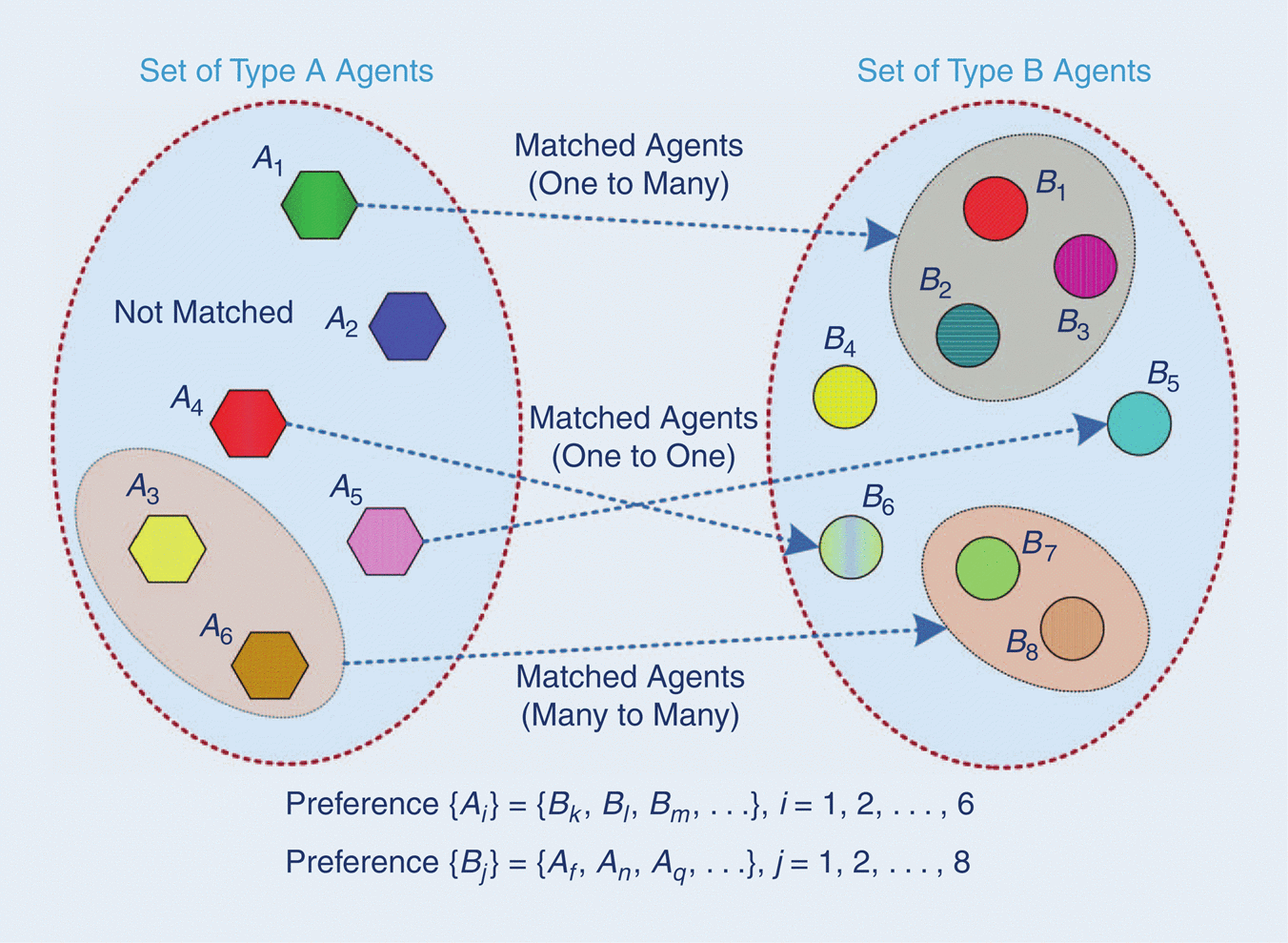
Matching theory considers explicitly the incentives that lead to build mutually beneficial relations among rational and selfish agents [25, 24], whose preferences are given by an arbitrary function. The outcome of the matching process, i.e., the pairing between D2MD groups and RBs in our case, is stable, and accurately reflects the system’s objectives. While matching theory, in general, cannot guarantee an optimal channel allocation pairing for the EE maximization, we will choose a preference function for the matches that is based on the aggregate interference level measured at the receivers. The rationale is that less interference implies less transmission power for the same rate and, since the rate is approximately linear in the SINR in the low and medium SINR regimes, the matches will be close to optimal. Our numerical results below support this claim. Fig. 1 illustrates the different scenarios that matching theory can address where D2MD groups are elements of set and CUE users are labeled as set . Clearly, the scenario previously discussed appears in one-to-one matches, whereas scenarios , and arise in one-to-many and many-to-many matches, respectively. We briefly review these different settings.
IV-A One-to-One Matching
In one-to-one matching, the objective is to find a mapping between every element in group and an element of group , such that the pairing of elements is stable, i.e., there do not exist two pairs and such that the objective function increases by swapping the images, namely and . In our setting, group is the set of D2MD transmitters, group is the set of RBs and the goal is to identify a match that causes the minimum possible interference. Specifically, the preference order relationship is defined as follows.
Given two disjoint sets for D2MD groups and for RBs, a one-to-one match is defined as a mapping from to such that for any , if then , and if for some then . The partner referred to as if . In addition,
-
1.
prefers to , if , denoted by ,
-
2.
prefers to , if , denoted by .
The received interference on D2MD groups for is
| (13) |
and for CUE is
| (14) |
Clearly,(12) and (13) take into account the accumulated interference on CUE and D2MD groups, respectively. Also note that the definition presents the outcome of the matching game as a two-sided preference, generally, that is, the allocation can be based on preferences posed by both the channels and the transmitters in the D2MD groups. The definition includes the case where a channel could be empty () or a D2MD group would be forbidden to transmit on any channel (), for completeness and for theoretical reasons. For application to a concrete case, the preference list of over , denoted by , is ranked by ascending order and similarly for CUE, , as shown in the example of Table III. The central entity then executes the Gale-Shapely algorithm [24] to obtain a stable match. Initially, group is allocated to channel , the first in its preference list. However, for we notice that it also prefers . At this step, the central entity checks preference list, and finds out that causes less interference than . Thus, swapping takes a place and will never be matched to again. The algorithm continues similarly until all groups are matched. The final outcome is .
| Groups | CUE | ||
|---|---|---|---|
| Groups | CUE | ||
|---|---|---|---|
IV-B Many-to-One Matching
Many-to-one matching arises naturally in our setting when a group of D2MD clusters are competing to use one of the available cellular resource blocks (type 2). The reuse factor limits the maximum number of clusters per RB. Differently to the one-to-one case, the choice of a D2MD group for a CUE can change depending on the accumulated interference from and other groups already allocated to . The same happens to CUE , for which the aggregated interference created by a group might affect the acceptance or rejection of a new D2MD. In detail, the preference relation is now defined in terms of the aggregated interference as follows:
Given two disjoint sets for D2MD groups and for RBs, a many-to-one match is defined as a mapping from to such that, for , if , then and if for some , then . The partner referred to as if .
-
1.
prefers to , if , this is denoted by ,
-
2.
prefers to , if , denoted by ,
-
3.
, where is reuse factor,
where and are calculated from (12) and (13). Note that condition 3) is simply a restatement of constraint (10g), so it provides one connection between the matching game and the power control subproblem. To compute the match, the central entity executes Gale-Shapely algorithm on several rounds, where a single D2MD group is allocated per round, i.e., reuse factor at first (Algorithm 1). So, the central entity first calculates interference as if it would in a one-to-one match (lines 1–4). The first round will result in some groups that will be less preferred by all the channels in their preference lists, and the central entity will allocate those groups in the ensuing rounds. Consider the example illustrated in Table IV with reuse factor . Notice that the number of CUEs is set to , half the amount in the one-to-one case, while the number of groups is still the same . In round one (lines 9 - 10), group will be allocated to . However, group has identical preference as thus, the central entity will check preference list (line 11). Obviously, causes less interference to so no swap action and than will be assigned to its next preference, i.e., . However, following the same logic for allocating to , a swap action will take a place and will be assigned to . By the end of round one the outcome is a match . Based on the obtained results, the algorithm re-calculates interference (line 25) to identify how much its level increases on channel for the allocated group when any of the free groups, i.e., and , are assigned. In a similar way, the algorithm calculates the amount of interference in a free group due to such combination. The goal is to execute the matching algorithm based on two-side preferences, so that users can be rearranged in groups causing the minimum mutual interference to each other.
IV-C Many-to-Many Matching
Many-to-many matching is required to deal with the general case of splitting and sharing. This can be seen from a resource management point of view as a user aiming to use a set of channels, and a RB that can be assigned to groups. The partnership relation can be defined in this case as follows knowing that and are calculated from (13) and (12).
Given two disjoint sets for D2MD groups and for RBs, a many-to-many match is defined as a deterministic mapping from to such that, for if , then and if for , then . The partner referred to as if .
-
1.
prefers to , if , denoted by ,
-
2.
prefers to , if , denoted by ,
-
3.
, where is reuse factor,
-
4.
, where is split factor.
Again, conditions 3) and 4) above are the constraints (10g) and (10f), respectively, and determine how the preference relationship is bound to the physical resources. The match is found in a similar way to the one-to-many case, but with a small difference (Algorithm 1). A small condition is added (in italic) to fulfill the split factor. The central entity will allocate the D2MD group to its favourite RBs. The main reason for choosing to start by the CUEs and then moving to groups, is to ensure that a set of CUEs does not interfere with each other. In the internal loop (lines 8–23), we guarantee the constraint of the split factor, where a group will receive a set of not more than RBs. Looking at the example of Table III with , will be allocated to and , forcing the group out of the unmatched groups list. However, the allocation remains open to any possible update, implying that if a different D2MD group is willing to use some of its RBs and the second group is more favorable, a swap takes place. This case appears (line 10) when we try to allocate , which has similar preferences as , but clearly for group is more preferred than group . Thus, the group chosen first is removed and sent back to the unmatched group list. By the end of round one, we will have , while the remaining groups are considered for the next round to share a RB with CUE and a D2MD. In the second round, the BS updates according to their preference lists (line 22). Then, the reuse factor is increased (line 24). As the mathematical model states, we allow groups to distribute their total rate and maximum transmission power over the allocated resources rather than enforcing them to equally divide those values. We remark that when a group is replaced by another due to CUE preference, it cannot be reallocated to the same CUE in the same round. The algorithm is a mix between one-to-many and one-to-one where we focus on the accumulated mutual interference to decide the candidate match.
IV-D Stability
The matching algorithms ensures that a CUE is allocated to its most preferred groups. This means that the preference of a D2MD group does not force us to assign a RB while there is a possibility for better pairing. This two-side preference guarantees that the matching algorithm converges to a stable solution. The partnership relation is stable if the pair () does not form a blocking pair which means , for any and any that are not matched with each other. To prove the stability we need to show that these two conditions cannot hold simultaneously. Assume that , thus a request had been sent to based on preference relation as the matching process implies. According to this, as is less preferred by based on the relation . This shows that even though is ’s favourite partner, yet is not interesting in being matched with . Thus, the condition does not hold. Similarly, the second condition can be proved and thus, the pair () cannot be a blocking pair for which proves that such a relationship is stable. However, in terms of optimality, there is an argument that this match can be one-side optimal as indicated in [24]. Thus, we compare our results with a greedy algorithm. This is not a problem for the power control algorithm as it is able to find the optimal values. For more details we refer the reader to [16].
V Optimal Power Control
Assume that the channel assignment is fixed. Then, the objective function (10) is a quotient between a non-concave function and a convex function, and the feasible set is convex. Thus, the problem of finding the optimal transmission powers falls into the general class of fractional programming problems, for which there exist efficient mathematical tools. For a convex set , and two non-negative functions and , a fractional program is the optimization problem
| (15) |
The key result to solve a fractional programming problem is the following theorem[26],
A point (14) if and only if , with being the unique zero of .
This theorem states that for solving a fractional programming problem it suffices to find the unique zero of . An efficient, well-known algorithm to do that is the Dinkelbach’s algorithm [26] (Alg.2). Its non-trivial step is the computation of the maximizer . However, if and are concave and convex, respectively, the latter calculation is a standard convex optimization sub-problem. Here, the feasible set is convex, but the numerator of the objective function is non-concave. For this reason, we shall use a sequential concave programming approach, approximating the numerator by a concave function as in [12]:
| (16) |
For maximizing the minimum energy-efficiency, just recall that the minimum of set of concave functions is also a concave function. Consequently, the generalized Dinkelbach’s algorithm (Alg.3- right) can be used to find the maximizer point. Algorithm 2 joins all the pieces together.
VI Numerical Results
We now present the numerical results obtained with the two-stage decomposition approach explained in previous Sections. We assume that the cellular users are spread over the cell area according to a homogeneous Poisson point process with density devices/m2. The cell is circular with radius equal to m, and a single (tagged) central entity is located at the center. Channel coefficients for each transmitter-receiver pair are subject to independent Rayleigh fading. For a general introduction to stochastic geometry models in wireless networks, see [27, 28, 29]. These models have been extensively used for modeling D2D communications [George15, 17], for general interference modeling [31, 32], for non-orthogonal communications [33] and, more recently, for millimeter wave wireless systems [34].
We have used two clustering algorithms for the grouping of the D2MD receivers:
-
1.
Nearest Neighbour (KNN). The heads of cluster (transmitters) are randomly selected among the points in . The rest of users/points in are considered as potential receivers assigned to the closest group head. Finally, only the groups that reach the target size are kept.
-
2.
Distance limited (DL) The number of clusters is specified in advance, as in KNN. However, the distance between transmitter/receivers is explicitly controlled with a parameter , defined as a fraction of the cell radius. Therefore, all users located within distance of some of the head clusters are retained as receivers. DL allows to form heterogeneous groups with unicast and multicast communications simultaneously.
Table V lists the physical parameters used during our numerical tests. In the plots reported in the rest of this Section, each point is the average of at least independent simulation runs. Confidence intervals for these runs have been computed, but have been omitted from the plots for clarity.
| Parameter | Value | Parameter | Value |
|---|---|---|---|
| Cell radius | m | Reuse factor () | |
| Network density () | devices/m2 | Minimum transmission rate | bi/s/Hz |
| Number of D2D groups | Maximum transmission powers | dBm | |
| Number of CUE users | Noise power density () | dBm/Hz | |
| Split factor () | Circuit Power | dBm | |
| Path loss exponent |
VI-A Performance Evaluation
First, we compare the performance of the matching-theory-based solution to a greedy algorithm. Differently from our approach, at each round, the greedy algorithm explores all the possible D2MD and CUE pairings via Algorithm 2. The CUE′ and D2MD′ achieving the highest energy efficiency are selected at each step. Though a greedy approach is not necessarily optimal, we have found that its performance is generally very close to the optimal solution, and the running time is substantially lower than an exhaustive search, whose complexity is exponential.
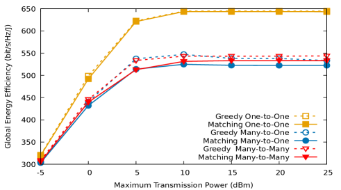
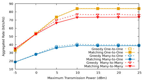
In D2MD, the greedy algorithm can be sensitive to variable group sizes. This is because larger clusters can achieve higher EE, which in turn may affect the selection of optimal pairs. For this reason, we use the KNN clustering technique in all the testing cases to guarantee a fair comparison. In the one-to-one matching scenario, we set D2MD groups of equal size with receivers and the minimum rate per channel is set to 0.1 bit/s/Hz. For the many-to-one matching scenario, we set the number of D2MD users to , the reuse factor is set to , the minimum rate per channel is set to 0.1 bit/s/Hz and the number of RBs is set to . Finally, in the many-to-many case, the number of clusters is , the number of RBs is , and the split and reuse factors are set to . In all the simulations, we vary the maximum transmission power per user in the range dBm. Fig. 2 depicts, respectively, the global EE and the aggregated rate, and exhibits that the results obtained with the proposed algorithm are close to optimal.
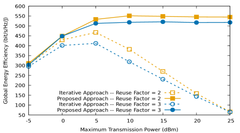
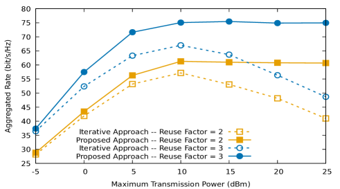
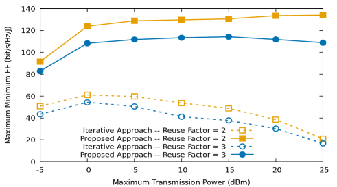
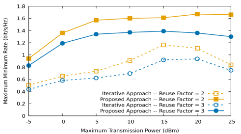
Secondly, we compare our results with the iterative matching algorithm from [15]. Similar configurations were used, but with , , , and . Fig. 3 and 4 illustrate both the system and the individual EE and rate. Clearly, EE increases monotonically with the power budget of a user until reaching a maximum. This happens at, approximately, the same values for our technique and for [15], but the latter shows a decreasing performance beyond that point. The graphs show that our algorithm handles better the aggregated interference, which in turn results in a significant performance improvement in both EE and rate.
VI-B One-to-One Matching
We use the DL clustering technique to create heterogeneous groups including both uni- and multi-casting. The CUE devices with the best channel quality are automatically chosen to share their RBs with the D2MD groups. Here, , and each group has receivers on average. The maximum distance between the head cluster and a receiver is approximately 50 m . The minimum rate per channel is set to 0.1 bit/s/Hz.
VI-B1 Feasibility and Convergence Rate
Since the location of the devices and the forming of clusters are random, it is not guaranteed that a given scenario is feasible for a specified set of constraints and power budget. For this reason, we always average our results over a constant number of feasible cases, to make comparisons fairer. At the same time, we kept track of the number of infeasible cases to have a clear idea about the effect of the power budget on the problem feasibility. Here, a feasible case is that all the users (CUE, D2MD) were able to satisfy both the minimum rate and maximum power constraints. When the number of D2MD users is , the total number of non-feasible cases started from , and went down to as the transmission power budget was increased. This number increases to (resp., ) when the number of transmitters increases to (resp., ), and reduces to as more transmission power was assigned to users during the maximization of the system EE. Similar values were observed for maximizing the minimum EE, where the non-feasible cases fell down to , , for a number of transmitters equal to , , , respectively. As expected, we found that, either for global EE or for max-min EE, feasibility increases with the power budget and decreases with the number of users, potentially producing higher interference. Nevertheless, note that because of the power optimization, the interference level is not necessarily proportional to the number of users. Further, we also measured (over the simulation runs) the number of iterations needed by the matching algorithm to converge. For , the matching algorithm converges in iterations, and for and , it converges in and iterations, respectively.
VI-B2 Energy Efficiency and Rate Analysis
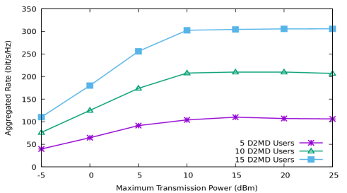
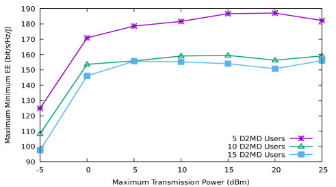
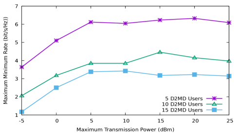
The effect of varying the maximum allowed transmission power is depicted in Fig. x, which shows the GEE in three different cases, . Clearly, energy efficiency increases with the power allocated to individual users, up to a peak point. This can be seen around , where GEE reaches its highest value at dBm. GEE remains almost constant beyond that point, only with small decrease. The same conclusions hold for MEE, as shown in Fig.x . In addition, we can clearly notice that the highest EE was achieved when the number of groups is the lowest. This is because the amount of drawn power continuously increases with the number of users. The average power used while maximizing the global EE rises from mW up to mW , while for an individual D2MD transmitter it falls between mW and mW . On the contrary, the global aggregated rate continuously increases as more users coexist in the network. Again, in all the experiments the rate reaches a saturation point where no further improvement is possible due to the aggregated interference.
| Min. Rate | GEE | Agg. Rate | MEE | User Rate |
|---|---|---|---|---|
VI-B3 Minimum Rate Constraints
The effect of a tighter rate constraint was also tested within the interval bit/s/Hz for the total rate. For ease of comparison with previous cases, the same configuration is kept with . In this test case, CUE and D2MD users are transmitting with a maximum power equal to dBm. Table VI shows that both GEE and global rate decrease when the rate constraint is stronger. This is a clear indication that setting a higher value for the total transmission rates forces the devices to use proportionally higher power in order to satisfy the constraint. Since rate increases only logarithmically with the SIR in the low or moderate SIR region, these higher rates do not compensate the extra energy expenditure.
VI-C Many-to-One Matching
| Many-to-One | Many-to-Many | |||||||
|---|---|---|---|---|---|---|---|---|
| Min. Rate | GEE | Agg. Rate | MEE | User Rate | GEE | Agg. Rate | MEE | User Rate |
Similarly, we applied the DL clustering algorithm to create clusters of an average size equal to . The distance ratio is , such that the head cluster is around m away from the receivers. Using the many-to-one matching algorithm for channel allocation, we aim to highlight the effect of the reuse factor on both EE and rate. Thus, we fix the number of cellular users and vary the reuse factor from to , for , respectively. Obviously, when , the experiment corresponds to one-to-one matching. The rest of system parameters remain the same as listed in Table V.
VI-C1 Feasibility and Convergence Rate
Tracking the percentage of feasible cases is also important with the matching-theoretic approach, since the range of allowed power budget could not yield for a feasible solution. The problem feasibility should become easier as the transmission power budget increases. Indeed, this is exactly what we observed, and coincides with the observations in previous numerical experiments. Regarding the convergence of the matching algorithm, it is again achieved in few iterations. For example, for and , the algorithm converges in , , , and iterations, for a reuse factor equal to , , and , respectively.
VI-C2 Energy Efficiency and Rate Analysis
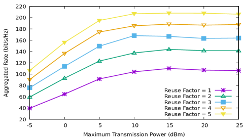
As Fig. 6 illustrates, both GEE and the aggregated rate increase with the power budget allocated to CUE and D2MD transmitters. However, when more D2MD clusters share the same RB, the interference becomes stronger, so users tend to use more power to guarantee the QoS constraints. For a reuse factor , the total needed power rises from mW up to mW for transmission powers equal to dBm and dBm, respectively. The total employed power when is mW and goes up to mW for maximum transmission powers equal to dBm and dBm, respectively. Thus, the total rate is higher when more users are allocated to a RB, yet this is not the case for GEE. Fig. 7 shows the minimum EE and the rate. Here, we see the impact of power and on individual users. We should mention that these values represent CUE/D2MD individual rate and EE. We notice that the behavior of both MEE and the minimum rate is similar to GEE and the aggregated rate as the users’ power budget increases.
VI-C3 Minimum Rate Constraints
Here, we investigate the effect of a tighter rate constraint within the interval bit/s/Hz on EE and rate for the many-to-one matching algorithm. The number of CUEs is set to , while the number of D2MD clusters is set to to satisfy the reuse factor . The maximum transmission budget for CUE and D2MD users is set to dBm. The results are illustrated in Table VII. Similar to the one-to-one scenario, both EE and rate decrease when the rate constraint is stronger. This is a clear illustration of the trade-off between energy efficiency and maximization of the sum-throughput when the system capacity has been already reached.
VI-D Many-to-Many Matching
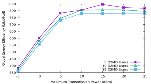
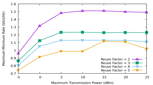
We complete our experiments by studying the influence of allowing D2MD groups to use more resources. Here, the DL clustering algorithm is applied to create groups of average size equal to . The number of clusters is fixed to while the available channels varies from with split factor equal to , respectively. The main reason for choosing these parameters is to ensure that the reuse factor is always satisfied. Thus, we force the presence of inter-groups interference and simulate the general case of resource allocation rather than a particular version of the many-to-one matching algorithm.
VI-D1 Feasibility and Convergence Rate
This were tested in the scenarios previously detailed. Obviously, solutions exist for the lowest transmission power (dBm), yet the number of non-feasible cases is considerably high (e.g., , and for DL). Increasing the D2MD power budget up to dBm significantly reduces the number of non-feasible cases down to for DL. Finally, the fractional programming algorithm 2 converges in an average of 7–8 rounds, though this figure increases with the amount of users. Moreover, we also considered the number of iterations needed by the matching algorithm to match all users and to satisfy and averaged over cases. For and , the matching algorithm converges in iterations. Holding the same number of clusters and while setting CUE to and and and , the matching algorithm converges in and iterations, respectively.
VI-D2 Minimum Rate Constraints
As in the previous cases, we study the effect of a tighter rate constraint when the total rate to be achieved over RBs is in the range of bit/s/Hz. For this, we set the number of D2MD to , CUE to and the split factor to . Moreover, to avoid the presence of extremely low throughput in any of the allocated RBs, we set the minimum rate per channel to . Table VII shows that both EE and rate decrease when the rate constraint is stronger, so the previous conclusions hold here too.
VI-D3 Energy Efficiency and Rate Analysis
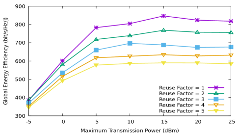
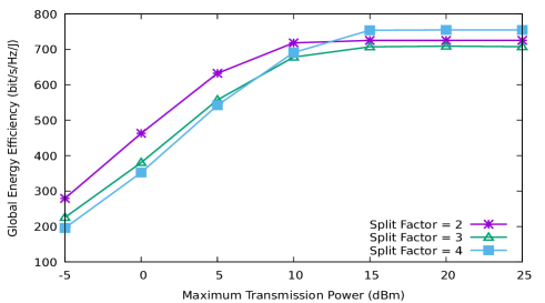
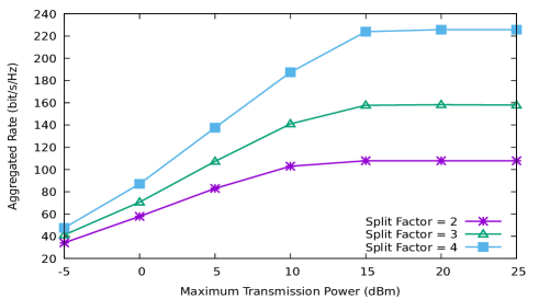
The sum-rate capacity and the energy efficiency were analysed over the range of maximum allowed transmission powers. Fig. 8 shows the aggregated rate for different split factors. Clearly, the aggregate rate increases with the maximum transmission power until the aggregate interference level prevents further gains. Moreover, as D2MD is able to use more RBs, the aggregated rate significantly improves. Notice that the behavior holds similar for GEE, as Fig.8 illustrates, yet the effect of does not: as more RBs are used, the needed power almost doubles from mW in DL for up to mW for , with a budget of dBm. Therefore, for the range of dBm we notice that better GEE is achieved when . However, this changes for the range between dBm and dBm, where higher rate values (saturation points) and stable drawn power ( – mW for DL) are obtained.
VI-E Discussion and Comparison Between Channel Allocation Scenarios
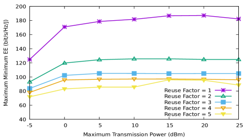
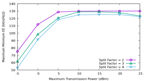
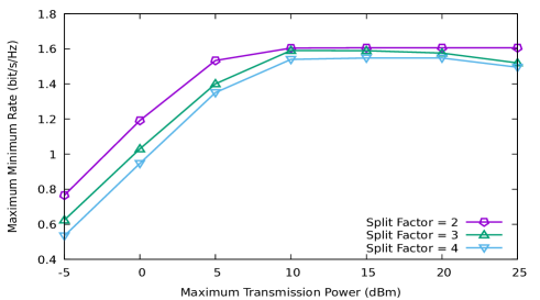
Generally, and for all the presented algorithms, we notice that the clustering techniques are not determinant to the fundamental performance for this type of systems. In fact, the EE and rate curves show similar shapes and there are only minor differences in their absolute values. In the one-to-one matching, we assign a single RB per D2MD where is equal to . Even though the GEE decreases compared to the aggregated rate, yet the gain in term of rate creates an acceptable balance, in particular, for low transmission power budgets as illustrated in Fig. 4. The same conclusion can be seen when applying the many-to-one matching algorithm. Here, with the minimum number of RBs in the one-to-one case ( RBs), the system supported up to D2MD clusters due to the reuse factor. Fig. 6 shows the difference between the two algorithms. Obviously, the more D2MD clusters are allocated to the same RB, the more transmission power will be used by transmitters to satisfy the QoS constraints in the shadow of the strong interference. Again, a small power budget creates a more controllable interference even when the reuse factor is quiet high ( D2MD cluster). This can be seen in the Fig. 6, when maximum transmission power is equal to dBm, such as the difference between EE values when is equal to is growing as the budget do. In the final algorithm, we introduce a split factor to investigate the effect of allocating more resources to a D2MD cluster. Here, we clearly notice that the more RBs, the more transmission budget is required to attain a high aggregated rate and to create the required balance. In MEE, we aim to maximize the minimum individual EE. Here, the user having the worst channel will always consume more transmission power to satisfy the QoS constraints. This is reflected in Fig. 7 with the one-to-one matching when interference is from one side (a CUE or a cluster). Clearly, as grows, the interference accumulates thus preventing the weakest user from achieving higher rate. Differently, in Fig. 9 with the many-to-many matching algorithm, the reuse factor is set to and the users are able to distribute power and rate over RBs. This scenario provided a low interference environment and high rate, mainly, for high power budgets.
As for the state information and signaling overhead required by our algorithms, we should mention that for the computations involved in the power control and channel assignment centralized problems, estimates of the channel gains are needed. These can be acquired through pilot sequences on a relatively slow time-scale in the case of slow fading. For the matching theory based solution to the channel assignment problem, the necessary channel state information is the aggregate interference level measured at each receiver/group. Since a D2MD transmitter needs to learn its weakest receiver (channel gain) and the aggregate interference level from its co-channel transmitters, near or distant, the signaling overhead is proportional to the number of receivers in its own group.
VII Conclusions
In this paper, we modelled the joint power and resource allocation problem to maximize the system and minimum individual energy efficiency. We have shown that the behavior of both global and individual energy efficiency is similar, with little dependence on the clustering of the devices, provided that clusters have an area that is not comparable with the cell area. We have provided a numerical framework for the planning and design of D2D and D2MD communications in wireless networks. Results from this framework indicate that fractional reuse of the resources, despite its complexity, can be beneficial for increasing the global energy efficiency with just minor degradation of the network sum-throughput. Therefore, a network design based on the optimization of energy efficiency for a given target throughput provides not only maximum energy efficiency, but also an adequate control of the interference level suffered by the receivers. The combination of matching theory and optimization used in the paper is essentially a centralized planning solution. Future work includes investigating partially or fully distributed implementations of the matching and optimization algorithms. Another interesting research direction is the analysis of the trade-off between optimal design and partial channel state information at the transmitters as a way to reduce complexity. Finally, investigating the performance for 5G wireless channels is another clear extension to this work.
[Complexity of the optimization problems]
The RB sharing and power control problems stated in (10) and (11) are NP-hard.
The theorem is proved by showing that the RB sharing and power control problem can be reduced in polynomial time to the integer partitioning problem: given a set of positive integers , determine if the set can be partitioned in two subsets having the same sum. Thus, we can assume that for some integer , since if the total sum were odd the partition is clearly impossible. The proof works for the version that maximizes the global energy efficiency, but is valid with straightforward modifications to the other two versions, the maximization of the minimum EE, and the maximization of the weighted sum of EEs.
Proof Recall that we have in our setting channels (or RBs) and CUEs. Assume for the rest of this proof that , i.e., only two groups of D2D users, and that the reuse and split factors are , . In words, each channel will support only one CUE and one group, and each D2MD group can potentially use all the channels. For simplicity in the notation, but without loss of generality, we may also assume that each D2MD group consist of only one pair of users (or even one user). This is not really a restriction, since we could equivalently assume that all the point-to-point channels between a given transmitter and the receivers in a group, say group , hace exactly the same quality.
Put , and set the noise power to and the SINR thresholds to , for . Now, set the channel gain parameters in the following fashion (equations (1) and (2)). Fix for all the CUEs , and set also for the D2MD transmitters , so that the D2MD groups do not cause interference to the CUEs. Set for ; ; and finally, for the cross-talk channels between the clusters. Note that the index in the latter parameters is void, since we are assuming a single user per cluster, and also that is by definition a number between zero and one.
Now, assume too that the consumption of the circuitry in the transmitters at rest is zero, that the maximum transmission powers in a CU an a D2MD group are and , respectively, and that the rate of a CUE is equal to . This value can only be reached if the CUEs use their maximum transmission power, by the way. Suppose now that the two groups use the same RB with powers and . As the channel gains for the cross-links are set to one, this means that , and . Since all the , both inequalities cannot hold simultaneously, and this means that the two groups cannot share any RB and must be assigned to different channels. As a consequence, since , the are not coupled by interference, and the two groups can use up to the available channels in mutual exclusion, i.e., with exactly one group (and one CUE) per RB. But if the SINR target f group has to be met, then its transmission power must be equal to
This transmission power is limited to per channel, so a feasible solution consisting in both groups using the channels, with only one D2MD transmitter in each group, would use at most. Since , a solution to the RB sharing and power control problem would give us immediately a solution to the partitioning problem. But the partitioning problem is NP-complete [30]. Because the transformation of the original problem into the partitioning problem is clearly polynomial, this proves that the RB sharing and power control problem is NP-complete, and consequently its optimization version is NP-hard.
References
- [1] Andrews, Jeffrey G and Buzzi, Stefano and Choi, Wan and Hanly, Stephen V and Lozano, Angel and Soong, Anthony C K and Zhang, Jianzhong Charlie What will 5G be?. In IEEE JJSAC, 1065–1082. IEEE, 2014.
- [2] Mach, Pavel and Becvar, Zdenek and Vanek, Tomas. In-Band Device-to-Device Communication in OFDMA Cellular Networks: A Survey and Challenges. In IEEE OCSTO, 2015. IEEE, 2015.
- [3] Zappone, Alessio and Björnson, Emil and Sanguinetti, Luca and Jorswieck, Eduard Globally Optimal Energy-Efficient Power Control and Receiver Design in Wireless Networks IEEE JSP, 2017.
- [4] Di Renzo, Marco and Zappone, Alessio and Lam, Thanh Tu and Debbah, Mérouane Resource allocation and power control based on user grouping for underlay device-to-device communications in cellular networks. Wiley Online Library, 2017.
- [5] Dinh-Van, Son and Shin, Yoan and Shin, Oh-Soon. Resource allocation and power control based on user grouping for underlay device-to-device communications in cellular networks Transactions on Emerging Telecommunications Technologies, 2015.
- [6] Alamouti, Sajjad Mehri and Sharafat, Ahmad R. Resource allocation for energy-efficient device-to-device communication in 4G networks. Telecommunications (IST), 2014 7th International Symposium on,1058–1063, 2015.
- [7] Kuhn, Harold W. The Hungarian Method for the assignment problem. Naval Research Logistics Quarterly, 1955.
- [8] Zhang, H and Song, L and Han, Z. Radio Resource Allocation for Device-to-Device Underlay Communication Using Hypergraph Theory IEEE JWCOM, 2016.
- [9] Zhou, Z and Dong, M and Ota, K and Wu, J and Sato, T Energy Efficiency and Spectral Efficiency Tradeoff in Device-to-Device (D2D) Communications IEEE Wireless Commun. Lett. IEEE 485–488 , 2014
- [10] Zhou, Z and Dong, M and Ota, K and Wu, J and Sato, T Resource allocation, interference management, and mode selection in device-to-device communication: A survey. Transactions on Emerging Telecommunications Technologies. IEEE 485–488 , 2017
- [11] Meshgi, Hadi and Zhao, Dongmei and Zheng, Rong Joint channel and power allocation in underlay multicast device-to-device communications. Communications (ICC), 2015 IEEE International Conference on. IEEE 2937–2942 , 2015
- [12] Meshgi, Hadi and Zhao, Dongmei and Zheng, Rong Optimal resource allocation in multicast device-to-device communications underlaying LTE networks. IEEE JVC. IEEE 8357–8371 , 2017
- [13] Li, Fangmin and Zhang, Yong and Al-Qaness, Mohammed Aide Multi-Objective Resource Allocation Scheme for {D2D} Multicast with {QoS} Guarantees in Cellular Networks. applied science 8357–8371 , 2016
- [14] Hamdi, Monia and Yuan, Di and Zaied, Mourad GA-based scheme for fair joint channel allocation and power control for underlaying D2D multicast communications Wireless Communications and Mobile Computing Conference (IWCMC), 2017 13th International 446–451, 2017
- [15] Zhou, Zhenyu and Ma, Guifang and Dong, Mianxiong and Ota, Kaoru and Xu, Chen and Jia, Yunjian Iterative Energy-Efficient Stable Matching Approach for Context-Aware Resource Allocation in D2D Communications IEEE , 2016
- [16] Hmila, Mariem and Fernández-Veiga, Manuel Energy-Efficient Power Control and Clustering in Underlay Device to Multi-device Communications Lecture Notes in Computer Science (including subseries Lecture Notes in Artificial Intelligence and Lecture Notes in Bioinformatics , 2017
- [17] Afshang, Mehrnaz and Dhillon, Harpreet and Chong, Peter Modeling and Performance Analysis of Clustered Device-to-Device Networks IEEE J WCOM , 2016
- [18] Shannon, C E A Mathematical Theory of Communication Bell System Technical Journal , 1948
- [19] Elsawy, Hesham and Hossain, Ekram and Haenggi, Martin Stochastic geometry for modeling, analysis, and design of multi-tier and cognitive cellular wireless networks: A survey IEEE OCSTO , 2013
- [20] Calcev, George and Chizhik, Dmitry and Goransson, Bo and Howard, Steven and Huang, Howard and Kogiantis, Achilles and Molisch, Andreas F. and Moustakas, Aris L. and Reed, Doug and Xu, Hao A Wideband Spatial Channel Model for System-Wide Simulations IEEE J VC , 2007
- [21] Zappone, Alessio and Sanguinetti, Luca and Bacci, Giacomo and Jorswieck, Eduard and Debbah, Mérouane Energy-efficient power control: A look at {5G} wireless technologies IEEE JSP 1668–1683 , 2016
- [22] Xu, Y and Wang, J and Wu, Q and Anpalagan, A and Yao, Y D Opportunistic Spectrum Access in Unknown Dynamic Environment: A Game-Theoretic Stochastic Learning Solution IEEE JWCOM 1380–1391 , 2012
- [23] Xu, Y and Wu, Q and Shen, L and Wang, J and Anpalagan, A Opportunistic Spectrum Access with Spatial Reuse: Graphical Game and Uncoupled Learning Solutions IEEE JWCOM 1380–1391 , 2013
- [24] Bayat, Siavash and Li, Yonghui and Song, Lingyang and Han, Zhu Matching Theory: Applications in wireless communications IEEE JSP 1498–1502, 2015
- [25] Gu, Yunan and Saad, Walid and Bennis, Mehdi and Debbah, Merouane and Han, Zhu Matching theory for future wireless networks: fundamentals and applications IEEE Communications Magazine 52–59, 2015
- [26] Dinkelbach, W On nonlinear fractional programming Manage. Sci., 1967
- [27] Haenggi, M and Andrews, J.G. and Baccelli, F and Dousse, O and Franceschetti, M Stochastic geometry and random graphs for the analysis and design of wireless networks IEEE JJSAC, 2009
- [28] Baccelli, François Stochastic Geometry and Wireless Networks: Volume II Applications INOW Publishers, 2010
- [29] Elsawy, Hesham and Hossain, Ekram and Haenggi, Martin Stochastic geometry for modeling, analysis, and design of multi-tier and cognitive cellular wireless networks: A survey IEEE OCSTO 996–1019 , 2013
- [30] Garey, M R and Johnson, D S and Garey, Michael R Computers and Intractability: A Guide to the Theory of NP-Completeness W H FREEMAN & CO isbn 0716710455 , 2011
- [31] Ak, S and Inaltekin, H and Poor, H V Gaussian approximation for the downlink interference in heterogeneous cellular networks 2016 IEEE International Symposium on Information Theory (ISIT), 2016
- [32] Ak, Serkan and Inaltekin, Hazer and Poor, H. Vincent A Tractable Framework for the Analysis of Dense Heterogeneous Cellular Networks IEEE JCOM, 2018
- [33] Tabassum, H and Hossain, E and Hossain, J Modeling and analysis of uplink non-orthogonal multiple access (NOMA) in large e-scale cellular networks using Poisson cluster processes CoRR, 2016
- [34] Venugopal, Kiran and Valenti, Matthew C and Heath, Robert W Device-to-Device Millimeter Wave Communications: Interference, Coverage, Rate, and Finite Topologies IEEE JWCOM 6175–6188 , 2016