Electromechanics in vertically coupled nanomembranes
Abstract
We investigate the electromechanical actuation of a pair of suspended silicon nitride membranes forming a monolithic optomechanical array. By controlling the membrane resonators’ tensile stress via a piezoelectrically controlled compressive force applied to the membrane chip we demonstrate noninvasive tuning of their mechanical mode spectrum, as well as strong intermode electromechanical coupling. Piezoelectric actuation is also shown to enhance the nonlinear response of the membranes, which is evidenced either by parametric amplification of the fundamental mode thermal fluctuations or by resonant driving of these modes into high amplitude states. Such an electro-optomechanical membrane array represents an attractive tunable and versatile platform for sensing, photonics and optomechanics applications.
Introduction–Electro-optomechanical systems involving high-quality nano/micromechanical resonators and integrating electric and optical degrees of freedom Midolo et al. (2018) are widely studied for sensing and photonic applications Ekinci and Roukes (2005); Li et al. (2007), as well as for fundamental investigations of the effects of radiation pressure in the context of optomechanics Aspelmeyer et al. (2014). Engineering linear and nonlinear electromechanical couplings in monolithic nanoresonator arrays is interesting for a wide range of ultrasensitive measurements Ekinci and Roukes (2005), photonics Fan et al. (2019), as well as for investigating collective dynamics, such as parametric resonances Turner et al. (1998), synchronization Shim et al. (2007); Matheny et al. (2014) or coherent phonon manipulations Mahboob et al. (2012); Faust et al. (2013); Okamoto et al. (2013); Mahboob et al. (2014); Yang et al. (2019); Hub (2019).
The combination of small effective mass, large area and high mechanical frequencies/quality factors makes suspended membranes made of low-loss material such as silicon nitride excellent resonators for optical sensing Reinhardt et al. (2016); Guo et al. (2017); Naesby et al. (2017) or electrooptical conversion Bagci et al. (2014); Andrews et al. (2014); Fink et al. (2016); Moaddel Haghighi et al. (2018) applications. The optomechanical interaction of such a membrane with an optical cavity field Thompson et al. (2008); Wilson et al. (2009) also allows for cooling its vibrations down into the quantum regime and observing radiation pressure-induced quantum effects Purdy et al. (2013a, b); Underwood et al. (2015); Peterson et al. (2016); Nielsen et al. (2017); Rossi et al. (2018).
Placing arrays of nanomembranes into an optical cavity Piergentili et al. (2018); Gärtner et al. (2018); Wei et al. (2019) furthermore opens up for exciting investigations of strong coupling and collective optomechanics Bhattacharya and Meystre (2008); Hartmann and Plenio (2008); Xuereb et al. (2012); Seok et al. (2012); Xuereb et al. (2014); Kipf and Agarwal (2014); Nair et al. (2016), as enhanced optomechanical effects are predicted, effective phonon-phonon interactions can be engineered and phenomena involving multiple electromagnetic modes and resonators can be studied. Tunability of the individual mechanical elements in such optomechanical arrays and integration of the electric degree of freedom are highly desirable, if not essential, for investigating collective effects such as collectively enhanced radiation pressure forces Xuereb et al. (2012); Nair et al. (2016), superradiance Kipf and Agarwal (2014), synchronization Bemani et al. (2017), topological interactions Xu et al. (2016), coherent phonon dynamics Xuereb et al. (2014) or entanglement and multimode squeezing generation Bhattacharya and Meystre (2008); Hartmann and Plenio (2008); Patil et al. (2015); Pontin et al. (2016).
In this letter we investigate the electromechanical actuation via piezoelectricity of a pair of suspended silicon nitride membranes forming a monolithic optomechanical array. The application of a piezoelectric compressive force to one of the membrane chips allows for modifying the tensile stress of the membranes and, thereby, for tuning their mechanical mode spectrum without deteriorating the mechanical quality factors of the resonances. Such a scheme was recently applied to a single membrane resonator Wu et al. (2018) and to a pair of distant membranes in an optical cavity Wei et al. (2019). We demonstrate here that the vibrational mode frequencies of two membranes in an 8.5 m-long monolithic array can be tuned to degeneracy and strongly coupled via the application of a static bias voltage to the piezoelectric transducer. We also observe parametric amplification Rugar and Grütter (1991) of the thermal fluctuations of their fundamental modes and demonstrate an enhancement of the nonlinear response of both membranes, evidenced by a lowering of the parametric oscillation thresholds and whose origin we discuss for each resonator.
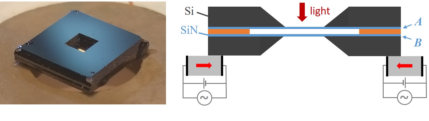
Electro-optomechanical array–The array used in this work consists in a pair of commercial Nor , high-stress, 500 m-square stochiometric silicon nitride thin films (thickness 92 m) deposited on a 5 mm-square silicon chip (thickness 500 m). The chips were assembled parallel with each other with an 8.5 m intermembrane separation (multilayer Si/Si/SiN spacer in Fig. 1) and their sides glued together at the corners following the method of Ref. Nair et al. (2017). Three corners of one of the chips were then glued to a 6 mm inner diameter piezoelectric ring transducer Nol , as shown in Fig. 1. The vibrations of the membranes in vacuum ( mbar) are monitored by optical interferometry by measuring the transmission through the array of monochromatic light provided by a tunable external cavity diode laser (890-940 nm). The array then acts as a short, low-finesse Fabry-Perot cavity, whose length fluctuations can be analyzed by tuning the laser wavelength so as to maximize their amplitude, and by analyzing their frequency content using a low resolution bandwidth spectrum analyzer. This specific array exhibits a worse degree of parallelism after assembly (the tilt between the membranes is estimated to be around 2 mrad) than previous similar arrays Nair et al. (2017), resulting in a slightly reduced interferometric displacement sensitivity. The lowest square drummodes of the membranes of this array, with MHz frequencies and mechanical quality factors in the range, can still be reliably characterized, as done in Naesby et al. (2017).
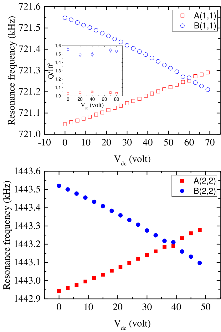
Tuning of mechanical mode spectrum–In the tensile stress-dominated regime the vibrational mode frequencies of the membrane resonators are given by , where MPa is the tensile stress, kg/m3 the density of silicon nitride, m the lateral dimension of the membrane and and are strictly positive integers. When a static compressive force is applied to the silicon frame, the tensile stress of both films is modified in such a way that opposite, linear frequency shifts with similar magnitude are observed for the and modes of each membrane over the bias voltage range 0-80V, as illustrated in Fig. 2. The compressive force on the bottom chip results in a reduced tensile stress for the silicon nitride film () deposited on this chip, and thereby a decreasing resonance frequency with positive bias voltage, as observed in Wu et al. (2018). The top chip, glued at its corners to the bottom one, then experiences an increased tensile stress and the resonance frequency of the membrane increases with bias voltage. Consistently with this picture, we tested that flipping the array and having the membrane chip glued to the transducer shows the opposite behavior, namely, a decrease in membrane’s resonance frequencies and an increase in the membrane’s. Piezoelectric biasing in the geometry of Fig. 1 thus allows for achieving frequency degeneracy of the (1,1) and (2,2) for bias voltages of 56 V and 38 V, respectively. Futhermore, no noticeable effect of the bias voltage on the mechanical quality factors was observed (inset of Fig. 2(a)), demonstrating the noninvasive nature of the scheme.
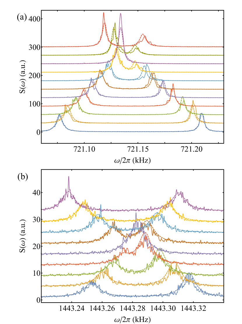
Interestingly, the intermode coupling via the frame/spacer structure can be investigated by analyzing the observed thermal noise spectrum around the degeneracy points, as shown in Fig. 3. This spectrum can be understood on the basis of a simple coupled oscillator model in which the dynamics of the mode amplitudes are given by
| (1) | ||||
| (2) |
where are the mode mechanical damping rates, their resonance frequencies at zero bias voltage, the linear voltage dependent frequency shifts, the intermode coupling constant and the thermal noise forces (divided by the mode effective mass). Fourier transforming these equations readily yields the Fourier component amplitudes at frequency , e.g.,
| (3) |
where () and with a similar expression for when exchanging subscripts and . The interferometric signal measured by the spectrum analyzer is proportional to the noise spectrum of , , whose analytical expression can then be obtained from the previous relations. The dashed lines in Fig. 3 show the results of a global fit of the data to the model, fixing the mechanical damping rates and thermal force amplitudes using the spectra far from the degeneracy points, and leaving as free parameters the voltage-dependent frequency shift rates , as well as the intermode coupling rate , defined by . The resulting spectra are observed to match well the observed data, in particular in the avoided crossing region, where the intermode coupling plays a significant role. Remarkably, the extracted value for the (1,1) modes, Hz, is found to be slightly larger than both mechanical decay rates Hz and Hz, which places such an electromechanical array at the border of the strong coupling regime. For the (2,2) modes, whose mechanical quality factors are a bit lower, Hz is slightly smaller than Hz. Such strong electromechanical couplings are promising for e.g. coherent phonon manipulations Mahboob et al. (2012); Faust et al. (2013); Okamoto et al. (2013) or electro-optical conversion Bagci et al. (2014); Andrews et al. (2014); Fink et al. (2016); Moaddel Haghighi et al. (2018).
Parametric actuation–We now turn to the piezoelectric tuning of the nonlinear response of the mechanics and investigate the parametric amplification Rugar and Grütter (1991); Turner et al. (1998); Carr et al. (2000); Mahboob and Yamaguchi (2008); Karabalin et al. (2010); Thomas et al. (2013); Mahboob et al. (2014); Seitner et al. (2017); Wu et al. (2018) of the thermal fluctuations of the fundamental modes of both membranes when, in addition to the dc bias voltage, a modulation at twice the mechanical resonance frequency, , is applied to the piezoelectric transducer. When one of these modes, with resonance frequency , is parametrically driven at , its dynamics can be described by the Mathieu equation Rugar and Grütter (1991)
| (4) |
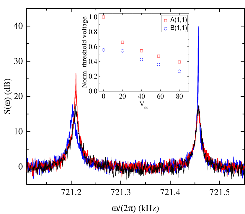
where includes the bias voltage shift and where is proportional to the parametric modulation amplitude . The bias voltage is chosen so as to operate away from the degeneracy point for the (1,1) modes, as well as far from resonance with the (2,2) modes, whose frequencies are close to the second harmonic of the fundamental frequencies (the absence of excitation of these modes was verified experimentally). Figure 4 shows examples of parametrically amplified noise spectra of both modes at zero bias voltage. The fluctuations of the mode which is parametrically driven resonantly are observed to strongly increase while its noise spectrum becomes narrower, as the parametric modulation amplitude increases, until the parametric oscillation threshold is reached when . Parametric gains of a few tens to a few hundreds are typically observed before the oscillation threshold is reached. The inset of Fig. 4 shows the variations with the bias voltage of the parametric oscillation threshold voltage of both modes; application of the bias voltage strongly reduces the parametric oscillation threshold of both membrane modes, in a seemingly relatively similar fashion.
The effect of the bias voltage on the response of each membrane is quite different in nature, though. To assess the effect of biasing on the dynamical response of the membranes, the (1,1) and (2,2) modes of each membranes were driven independently at their mechanical resonance frequency, for a fixed bias voltage and increasing modulation amplitudes, as shown in Fig. 5. A linear response is observed over a wide range of modulation amplitudes, before nonlinearities kick in Yang et al. (2019). The linear response of the modes of membrane –which is directly coupled to the piezoelectrically stressed silicon frame–is strongly affected by the bias voltage; in particular, its increased response at accounts well for the decrease of the parametric oscillation threshold with .
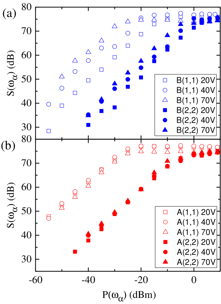
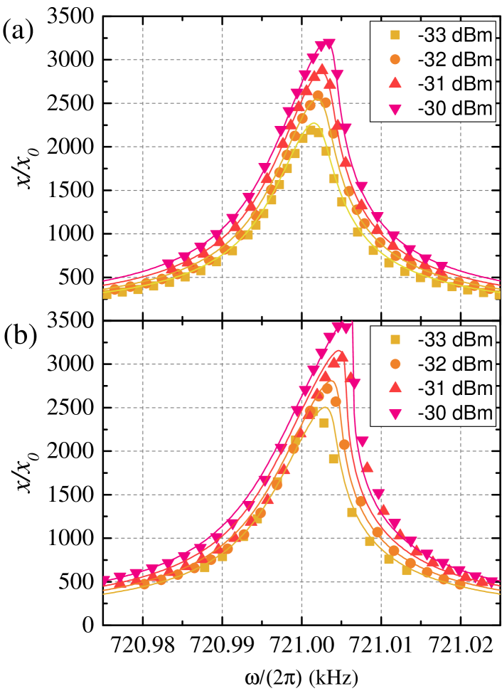
In contrast, such a direct parametric modulation of the spring constant does not explain the lowering of the parametric oscillation threshold for , as the linear response of the modes of membrane –whether at the fundamental or the second harmonic frequency–is fairly independent of the bias voltage. To investigate the role of the biasing on the nonlinear response of membrane further, its fundamental mode was driven in the high amplitude regime before the onset of bistability. Frequency scans around of the signal measured by the spectrum analyzer in zero-span mode were performed for different drive powers and different bias voltages. These scans, shown in Figs. 6, clearly show nonlinearly distorted resonance profiles. Such profiles can be accurately reproduced by introducing a cubic Duffing nonlinearity in the equation of motion for the mode dynamics
| (5) |
where is the amplitude of the driving force at frequency and is the Duffing nonlinearity coefficient. For a small nonlinearity and neglecting the thermal force, the Fourier component amplitude at is approximately given by a solution of the implicit equation Jordan and Smith (1987)
| (6) |
The solid lines in Figs. 6 show the results of global fits of this equation to the data, using low drive power scans to fix and and leaving as free parameters and a global amplitude for the driving force, the respective amplitudes being apppropriately scaled by the known applied powers. The fits match well the observed spectra and yield values of (in units of ) of and for V and 80 V, respectively. Application of a bias voltage thus increases the nonlinear response of membrane to a driving force at the resonance frequency . Since the nonlinear Duffing term in in Eq. (5) under such a driving can be seen to represent an effective modulation at twice the resonance frequency, as in Eq. (4), the bias voltage-dependent Duffing nonlinearity coefficient is thus expected to be proportional to the parametric modulation coefficient , itself inversely proportional to . This is corroborated by the 60% increase in when increasing the bias voltage from 20 V to 80 V, which matches well the observed reduction in the parametric oscillation threshold voltage by about the same amount. Piezoelectric actuation can thus be used to enhance the nonlinear response of both resonators, which is interesting for generating thermomechanical squeezing or entanglement Rugar and Grütter (1991); Mahboob et al. (2014); Wu et al. (2018); Hub (2019), among others.
Conclusion–A simple and noninvasive scheme, based on piezoelectrically-induced stress control, for tuning the vibrational mode frequencies and the nonlinear response of high-Q suspended membrane resonators in a monolithic optomechanical array has been demonstrated. While enhancing their nonlinear response is useful for various sensing applications, tuning the mechanics and engineering electromechanical couplings in such electro-optomechanical arrays is essential for future collective optomechanics investigations.
Acknowledgements.
We acknowledge support from the Velux Foundations.References
- Midolo et al. (2018) L. Midolo, A. Schliesser, and A. Fiore, Nature Nanotechnology 13, 11 (2018).
- Ekinci and Roukes (2005) K. L. Ekinci and M. L. Roukes, Review of Scientific Instruments 76, 061101 (2005).
- Li et al. (2007) M. Li, H. X. Tang, and M. L. Roukes, Nature Nanotechnology 2, 114 (2007).
- Aspelmeyer et al. (2014) M. Aspelmeyer, T. J. Kippenberg, and F. Marquardt, Reviews of Modern Physics 86, 1391 (2014).
- Fan et al. (2019) L. Fan, C.-L. Zou, N. Zhu, and H. X. Tang, Nature Photonics 13, 323 (2019).
- Turner et al. (1998) K. L. Turner, S. A. Miller, P. G. Hartwell, N. C. MacDonald, S. H. Strogatz, and S. G. Adams, Nature 396, 149 (1998).
- Shim et al. (2007) S.-B. Shim, M. Imboden, and P. Mohanty, Science 316, 95 (2007).
- Matheny et al. (2014) M. H. Matheny, M. Grau, L. G. Villanueva, R. B. Karabalin, M. C. Cross, and M. L. Roukes, Phys. Rev. Lett. 112, 014101 (2014).
- Mahboob et al. (2012) I. Mahboob, K. Nishiguchi, H. Okamoto, and H. Yamaguchi, Nature Physics 8, 503 (2012).
- Faust et al. (2013) T. Faust, J. Rieger, M. J. Seitner, J. P. Kotthaus, and E. M. Weig, Nature Physics 9, 485 (2013).
- Okamoto et al. (2013) H. Okamoto, A. Gourgout, C.-Y. Chang, K. Onomitsu, I. Mahboob, E. Y. Chang, and H. Yamaguchi, Nature Physics 9, 480 (2013).
- Mahboob et al. (2014) I. Mahboob, H. Okamoto, K. Onomitsu, and H. Yamaguchi, Phys. Rev. Lett. 113, 167203 (2014).
- Yang et al. (2019) F. Yang, F. Rochau, J. S. Huber, A. Brieussel, G. Rastelli, E. M. Weig, and E. Scheer, Phys. Rev. Lett. 122, 154301 (2019).
- Hub (2019) (2019).
- Reinhardt et al. (2016) C. Reinhardt, T. Müller, A. Bourassa, and J. C. Sankey, Phys. Rev. X 6, 021001 (2016).
- Guo et al. (2017) J. Guo, R. A. Norte, and S. Gröblacher, Opt. Express 25, 9196 (2017).
- Naesby et al. (2017) A. Naesby, S. Naserbakht, and A. Dantan, Applied Physics Letters 111, 201103 (2017).
- Bagci et al. (2014) T. Bagci, A. Simonsen, S. Schmid, L. G. Villanueva, E. Zeuthen, J. Appel, J. M. Taylor, A. Sørensen, K. Usami, A. Schliesser, and E. S. Polzik, Nature 507, 81 (2014).
- Andrews et al. (2014) R. W. Andrews, R. W. Peterson, T. P. Purdy, K. Cicak, R. W. Simmonds, C. A. Regal, and K. W. Lehnert, Nature Physics 10, 321 (2014).
- Fink et al. (2016) J. M. Fink, M. Kalaee, A. Pitanti, R. Norte, L. Heinzle, M. Davanço, K. Srinivasan, and O. Painter, Nature Communications 7, 12396 (2016).
- Moaddel Haghighi et al. (2018) I. Moaddel Haghighi, N. Malossi, R. Natali, G. Di Giuseppe, and D. Vitali, Phys. Rev. Applied 9, 034031 (2018).
- Thompson et al. (2008) J. D. Thompson, B. M. Zwickl, A. M. Jayich, F. Marquardt, S. M. Girvin, and J. G. E. Harris, Nature 452, 72 (2008).
- Wilson et al. (2009) D. J. Wilson, C. A. Regal, S. B. Papp, and H. J. Kimble, Phys. Rev. Lett. 103, 207204 (2009).
- Purdy et al. (2013a) T. P. Purdy, R. W. Peterson, and C. A. Regal, Science 339, 801 (2013a).
- Purdy et al. (2013b) T. P. Purdy, P.-L. Yu, R. W. Peterson, N. S. Kampel, and C. A. Regal, Phys. Rev. X 3, 031012 (2013b).
- Underwood et al. (2015) M. Underwood, D. Mason, D. Lee, H. Xu, L. Jiang, A. B. Shkarin, K. Børkje, S. M. Girvin, and J. G. E. Harris, Phys. Rev. A 92, 061801 (2015).
- Peterson et al. (2016) R. W. Peterson, T. P. Purdy, N. S. Kampel, R. W. Andrews, P.-L. Yu, K. W. Lehnert, and C. A. Regal, Phys. Rev. Lett. 116, 063601 (2016).
- Nielsen et al. (2017) W. H. P. Nielsen, Y. Tsaturyan, C. B. Møller, E. S. Polzik, and A. Schliesser, Proceedings of the National Academy of Sciences of the United States of America 114, 62 (2017).
- Rossi et al. (2018) M. Rossi, D. Mason, J. Chen, Y. Tsaturyan, and A. Schliesser, Nature 563, 53 (2018).
- Piergentili et al. (2018) P. Piergentili, L. Catalini, M. Bawaj, S. Zippilli, N. Malossi, R. Natali, D. Vitali, and G. D. Giuseppe, New Journal of Physics 20, 083024 (2018).
- Gärtner et al. (2018) C. Gärtner, J. P. Moura, W. Haaxman, R. A. Norte, and S. Gröblacher, Nano letters 18, 7171 (2018).
- Wei et al. (2019) X. Wei, J. Sheng, C. Yang, Y. Wu, and H. Wu, Phys. Rev. A 99, 023851 (2019).
- Bhattacharya and Meystre (2008) M. Bhattacharya and P. Meystre, Phys. Rev. A 78, 041801 (2008).
- Hartmann and Plenio (2008) M. J. Hartmann and M. B. Plenio, Phys. Rev. Lett. 101, 200503 (2008).
- Xuereb et al. (2012) A. Xuereb, C. Genes, and A. Dantan, Phys. Rev. Lett. 109, 223601 (2012).
- Seok et al. (2012) H. Seok, L. F. Buchmann, S. Singh, and P. Meystre, Phys. Rev. A 86, 063829 (2012).
- Xuereb et al. (2014) A. Xuereb, C. Genes, G. Pupillo, M. Paternostro, and A. Dantan, Phys. Rev. Lett. 112, 133604 (2014).
- Kipf and Agarwal (2014) T. Kipf and G. S. Agarwal, Phys. Rev. A 90, 053808 (2014).
- Nair et al. (2016) B. Nair, A. Xuereb, and A. Dantan, Phys. Rev. A 94, 053812 (2016).
- Bemani et al. (2017) F. Bemani, A. Motazedifard, R. Roknizadeh, M. H. Naderi, and D. Vitali, Phys. Rev. A 96, 023805 (2017).
- Xu et al. (2016) H. Xu, D. Mason, L. Jiang, and J. G. E. Harris, Nature 80, 537 (2016).
- Patil et al. (2015) Y. S. Patil, S. Chakram, L. Chang, and M. Vengalattore, Phys. Rev. Lett. 115, 017202 (2015).
- Pontin et al. (2016) A. Pontin, M. Bonaldi, A. Borrielli, L. Marconi, F. Marino, G. Pandraud, G. A. Prodi, P. M. Sarro, E. Serra, and F. Marin, Phys. Rev. Lett. 116, 103601 (2016).
- Wu et al. (2018) S. Wu, J. Sheng, X. Zhang, Y. Wu, and H. Wu, AIP Advances 8, 015209 (2018).
- Rugar and Grütter (1991) D. Rugar and P. Grütter, Phys. Rev. Lett. 67, 699 (1991).
- (46) Norcada Inc.
- Nair et al. (2017) B. Nair, A. Naesby, and A. Dantan, Opt. Lett. 42, 1341 (2017).
- (48) Noliac NAC2123.
- Carr et al. (2000) D. W. Carr, S. Evoy, L. Sekaric, H. G. Craighead, and J. M. Parpia, Applied Physics Letters 77, 1545 (2000).
- Mahboob and Yamaguchi (2008) I. Mahboob and H. Yamaguchi, Applied Physics Letters 92, 173109 (2008).
- Karabalin et al. (2010) R. B. Karabalin, S. C. Masmanidis, and M. L. Roukes, Applied Physics Letters 97, 183101 (2010).
- Thomas et al. (2013) O. Thomas, F. Mathieu, W. Mansfield, C. Huang, S. Trolier-McKinstry, and L. Nicu, Applied Physics Letters 102, 163504 (2013).
- Seitner et al. (2017) M. J. Seitner, M. Abdi, A. Ridolfo, M. J. Hartmann, and E. M. Weig, Phys. Rev. Lett. 118, 254301 (2017).
- Jordan and Smith (1987) D. W. Jordan and P. Smith, Oxford, Clarendon Press (1987).