Flopping-mode electric dipole spin resonance
Abstract
Traditional approaches to controlling single spins in quantum dots require the generation of large electromagnetic fields to drive many Rabi oscillations within the spin coherence time. We demonstrate “flopping-mode” electric dipole spin resonance, where an electron is electrically driven in a Si/SiGe double quantum dot in the presence of a large magnetic field gradient. At zero detuning, charge delocalization across the double quantum dot enhances coupling to the drive field and enables low power electric dipole spin resonance. Through dispersive measurements of the single electron spin state, we demonstrate a nearly three order of magnitude improvement in driving efficiency using flopping-mode resonance, which should facilitate low power spin control in quantum dot arrays.
Recent advances in silicon spin qubits have bolstered their standing as a platform for scalable quantum information processing. As single-qubit gate fidelities exceed 99.9 Yoneda et al. (2018), two-qubit gate fidelities improve Veldhorst et al. (2015); Xue et al. ; Huang et al. ; Zajac et al. (2018); Watson et al. (2018), and the field accelerates towards large multi-qubit arrays Mortemousque et al. ; Mills et al. (2019), developing the tools necessary for efficient and scalable spin control is critical Hanson et al. (2007). While it is possible to implement single electron spin resonance in quantum dots (QDs) using ac magnetic fields Koppens et al. (2006), the requisite high drive powers and associated heat loads are technically challenging and place limitations on attainable Rabi frequencies Takeda et al. (2016). As spin systems are scaled beyond a few qubits, methods of spin control which minimize dissipation and reduce qubit crosstalk will be important for low temperature quantum information processing Hornibrook et al. (2015).
Electric dipole spin resonance (EDSR) is an alternative to conventional electron spin resonance. In EDSR, static gradient magnetic fields and oscillating electric fields are used to drive spin rotations Rashba and Efros (2003). The origin of the effective magnetic field gradient varies across implementations: intrinsic spin-orbit coupling Golovach et al. (2006); Flindt et al. (2006); Nowack et al. (2007), hyperfine coupling Laird et al. (2007), and -factor modulation Kato et al. (2003) have been used to couple electric fields to spin states. The inhomogeneous magnetic field generated by a micromagnet Pioro-Ladrière et al. (2008); Kawakami et al. (2014) has been used to create a synthetic spin-orbit field for EDSR, enabling high fidelity control Yoneda et al. (2018). Conveniently, this magnetic field gradient gives rise to a spatially varying Zeeman splitting, enabling spins in neighboring QDs to be selectively addressed Pioro-Ladrière et al. (2008); Obata et al. (2010); Nadj-Perge et al. (2010); Yoneda et al. (2014); Noiri et al. (2016); Takeda et al. (2016); Ito et al. (2018).
In this Letter, we demonstrate a novel mechanism for driving low-power, coherent spin rotations, which we call “flopping-mode EDSR”. In conventional EDSR, the electric drive field couples to a charge trapped in a single quantum dot, leading to a relatively small electronic displacement Nowack et al. (2007). We instead drive single spin rotations in a DQD close to zero detuning, = 0, where the electric field can force the electron to flop back and forth between the left and right dots, thereby sampling a larger variation in transverse magnetic field. We call this configuration the “flopping-mode”.
Neglecting spin, the Hamiltonian describing a single electron trapped in a DQD is given by = + , where is the interdot tunnel coupling and are the Pauli operators in position (L, R) space Hayashi et al. (2003). In the highly detuned regime of a DQD (with ), the electron is strongly localized in either the left or right dot, and the relevant orbital energy scale is 3–5 meV. In contrast, when = 0 the charge delocalizes across the DQD leading to the formation of bonding and antibonding states = . Here the bonding-antibonding energy difference 20–40 eV is dominant and the charge is much more susceptible to oscillating electric drive fields Hu et al. (2012); Kim et al. (2015).
The application of a magnetic field results in Zeeman splitting of the spin states. When the Zeeman energy and tunnel splitting at = 0 are comparable, the combination of a magnetic field gradient and the large electric dipole moment result in strong spin-charge hybridization. This allows electric fields to couple to spin indirectly via the charge Viennot et al. (2015); Mi et al. (2018); Samkharadze et al. (2018). We coherently manipulate a single-electron spin qubit in the flopping-mode regime and find that the power required to drive Rabi oscillations is almost three orders of magnitude less than in single dot EDSR. In addition to improving the spin sensitivity to electric fields, there is a “sweet spot” at = 0 where charge noise is suppressed Vion et al. (2002), leading to a four-fold improvement in qubit quality factor.
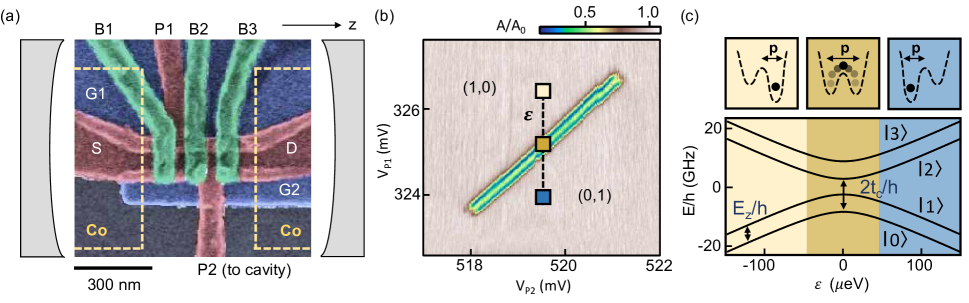
The device consists of two single-electron natural-Si/SiGe DQDs (DQD1 and DQD2) that are embedded in a half-wavelength niobium superconducting cavity with resonance frequency = 5.846 GHz Mi et al. (2018). A false-color scanning electron microscope (SEM) image of one of the DQDs is shown in Fig. 1(a). For the purposes of this experiment, only one DQD is active at a time. Electronic confinement is achieved using an overlapping aluminum gate stack Zajac et al. (2016). For each DQD, the plunger gate P2 is connected to the center pin of the superconducting cavity, efficiently coupling the charge confined in the DQD to the electric field of the cavity.
Cobalt micromagnets [yellow dashed lines in Fig. 1(a)] generate a local magnetic field gradient with longitudinal and transverse components. The total magnetic field at the device is the sum of the external magnetic field applied in the z direction, and the stray field from the micromagnet . As a result, the total magnetic field is a sensitive function of position in the DQD confinement potential. The micromagnet enables EDSR Pioro-Ladrière et al. (2008); Kawakami et al. (2014) and gives rise to spin-photon coupling, which is utilized here solely for dispersive cavity readout of the spin state Petersson et al. (2012); Mi et al. (2018).
We first probe the charge degree of freedom with = 0 by measuring the cavity transmission amplitude in the single photon regime, as a function of the gate voltages and [see Fig. 1(b)]. These data are acquired near the (1,0)–(0,1) interdot charge transition with the probe frequency equal to the cavity frequency = . Here (, ) denotes the charge occupancy of the DQD, where is the number of electrons in the left(right) dot. Around = 0, where the DQD is maximally polarizable, electric fields from the cavity result in charge dynamics within the DQD that load the superconducting cavity and reduce Petersson et al. (2012); Frey et al. (2012). Neglecting spin, the energy difference between the bonding and antibonding charge states is = . In the case where < , there will be two values of detuning where = ( is Planck’s constant). Around these values of detuning the cavity response is substantial, as is evident from the data in Fig. 1(b) Frey et al. (2012); Petersson et al. (2012). Since the flopping-mode EDSR mechanism is based on charge motion in a magnetic field gradient, it will also be most effective near = 0, where the charge dipole moment is largest [Fig. 1(c)].
In the presence of a micromagnet and external magnetic field, the Hamiltonian describing the one-electron DQD is
| (1) |
where are the Pauli operators in spin space, is the homogeneous magnetic field component in the z direction, is the electronic -factor, and is the Bohr magneton Benito et al. (2017). In general, will generate longitudinal and transverse (, ) gradients that will modify the energy level spectrum. We define 2 ( = , , ) as the difference in total magnetic field between the left and right dots in the direction. Without loss of generality, we take = 0 in the remainder of the Letter Benito et al. . The total magnetic field components at the left and right dots can be written as = and = , where is the homogeneous magnetic field in the z(x) direction. For our micromagnet design, we expect 0, but note that in the case where 0, the geometric coordinate system can always be rotated to satisfy = 0 Benito et al. . The Zeeman energy is given by = .
Zeeman splitting of the bonding/antibonding states leads to the 4-level system shown in Fig. 1(c), where refer to the spin-down and spin-up bonding states, and to the spin-down and spin-up antibonding states. Spin-preserving interdot tunnel coupling results in the anticrossings near = 0. The component gives rise to a spatially varying longitudinal field such that the energy splitting between the ground and first excited state can vary significantly in the far detuned limits, e.g. versus . The transverse components of the micromagnet field hybridize the spin-orbital states near = 0 and lead to spin-photon coupling Benito et al. (2017); Mi et al. (2018), which enables dispersive spin state readout Petersson et al. (2012).
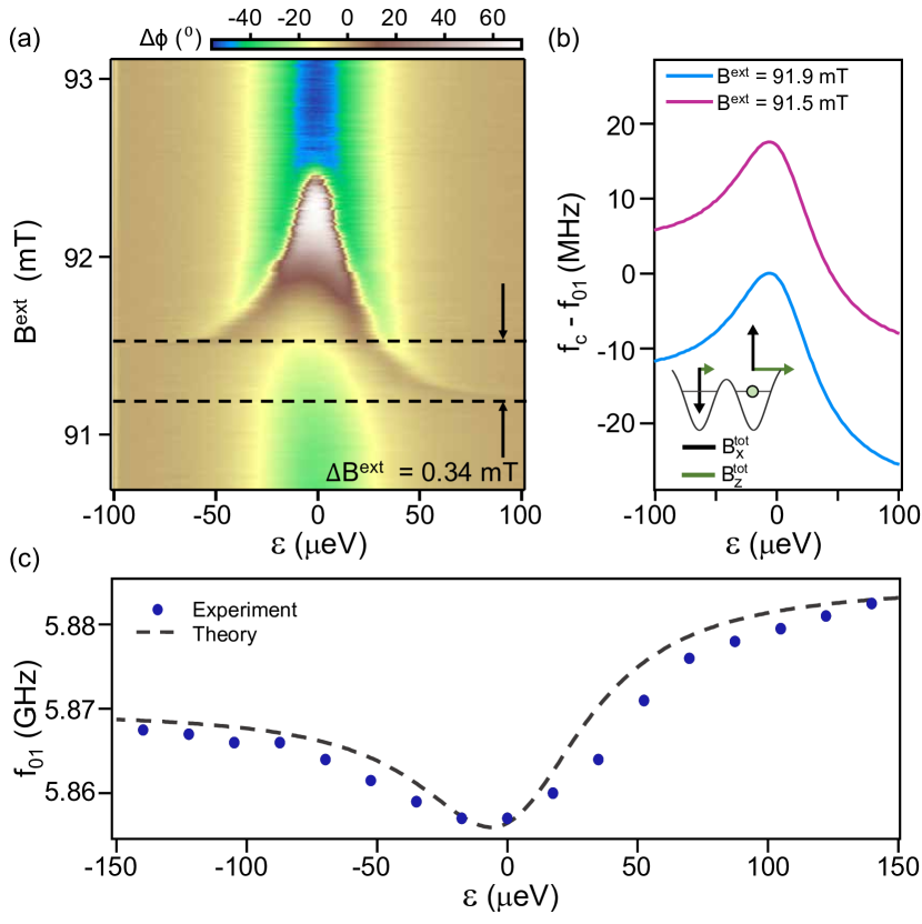
In general, the electron spin resonance condition will be a function of detuning owing to the magnetic field gradients. To investigate the flopping-mode EDSR mechanism, we first map out the spin resonance condition by measuring the cavity phase shift as a function of and [Fig. 2(a)]. The funnel-shaped feature in Fig. 2(a) is a consequence of detuning-dependent charge hybridization and Zeeman physics Benito et al. (2017); Samkharadze et al. (2018) in the regime where . At low , the spin transition is detuned from the cavity, but there is still a small phase response around = 0 due to the large electric dipole moment Frey et al. (2012); Petersson et al. (2012). At large detunings () the energy splitting is dominated by Zeeman physics. At small detunings, levels and hybridize due to transverse magnetic fields Benito et al. (2017). This spin-charge hybridization pulls slightly below the Zeeman energy. As a result, when is slightly less than at = 0, there are two values of finite detuning for which is on resonance with the cavity, giving rise to the wings of the funnel-shaped feature that begins at 91.2 mT. As increases further the values of detuning that lead to resonance with the cavity shift closer to = 0. Eventually, at 91.9 mT, the two resonance conditions merge at = 0. Figure 2(b) shows theoretical predictions for as a function of for = 91.5 mT and 91.9 mT, with .
With the electron spin resonance frequency now mapped out as a function of and , we can drive coherent single spin rotations using flopping-mode EDSR. At = 0, a microwave burst of frequency and duration is applied to gate P1 to drive coherent spin rotations. The final spin state is read out dispersively at = 0 by measuring the cavity phase response Mi et al. (2018).
A typical flopping-mode dataset is shown in Fig. 3(a), where is plotted as a function of and . As expected, the Rabi oscillation visibility is maximal when is resonant with . The spin transition frequency is plotted in Fig. 2(c) as a function of . When , the lowest occurs near = 0 due to spin-charge hybridization, and increases as increases. The trends in these data are in general agreement with the data measured using microwave spectroscopy in Fig. 2(a). The asymmetry of the data in Figs. 2(a) and (c) about = 0 is due to the longitudinal gradient field . Using the expression 2 = (1+), where is the micromagnet magnetic susceptibility Mi et al. (2018) and = 0.34 mT [from data in Fig. 2(a)], we find = 0.27 mT. We take this value and fit the data in Fig. 2(c), finding good agreement between experiment and our theoretical model.
Having gained a quantitative understanding of how depends on , we now compare EDSR in the flopping-mode and single dot regimes. By simultaneously applying a microwave burst and square pulse to gate P1, we can drive coherent spin rotations at a value of detuning set by the amplitude of the square pulse. Due to the ratio of electric dipole moments in these regimes, the power required to drive fast coherent rotations in the single dot regime is expected to be much higher. As shown in the upper panel of Fig. 3(b), at = 0 a Rabi frequency 6 MHz is achieved with = -84 dBm at the device. In contrast, when = -52 eV a power of = -77 dBm is required to achieve approximately the same Rabi frequency [see Fig. 3(b), lower panel]. The actual power at the gate is determined by measuring the envelope of Landau-Zener-Stueckelberg interference fringes as a function of increasing Shevchenko et al. (2010). We fit the Rabi oscillations to an exponentially decaying sinusoid with = 1.4 s at = 0 eV and = 0.24 s at = -52 eV.
The full crossover from the single dot to the flopping-mode regime is examined over a 300 eV range of detuning in Fig. 4(a). Here we plot the power required to achieve 6 MHz Rabi oscillations as a function of . The data are nearly symmetric about = 0, as expected from the detuning symmetry of the energy levels. Most importantly, these data show that 250 less microwave power is required to achieve a 6–8 MHz at = 0 compared to the standard single dot EDSR regime.
From theory Benito et al. , the drive power required to drive Rabi oscillations at frequency is given by
| (2) |
where = 0.003 is a fitting parameter that accounts for single dot EDSR in the far-detuned limits () Golovach et al. (2006); Flindt et al. (2006). We fit the data in Fig. 4(a) to Eq. (2), obtaining close agreement between theory and experiment.
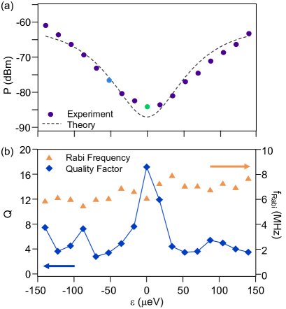
A charge noise sweet spot exists when / Vion et al. (2002). In the absence of a longitudinal () gradient the sweet spot occurs at = 0. Theory predicts that a gradient may shift the sweet spot to finite detuning, or if the gradient field is large enough, destroy it entirely Benito et al. . We search for evidence of a sweet spot by examining the quality factor of -rotations as a function of detuning Yoneda et al. (2018). At each value of detuning, a Rabi chevron is acquired with set to achieve 6 MHz, similar to Fig. 3(a). We take a Fourier transform of each column of the chevron and identify . At this , we fit the Rabi oscillations as a function of to extract and .
The Rabi frequency and -factor are plotted as a function of in Fig. 4(b). At finite detuning 4. We observe more than a four-fold increase in the quality factor, with = 18 at = 0. The enhancement of in the flopping-mode regime can be attributed to the presence of the charge noise sweet spot, which to first order decouples the spin from electrical detuning noise. While the factors achieved here are lower than those reported elsewhere Yoneda et al. (2018); Zajac et al. (2018), we expect that optimizing and fabricating devices on enriched 28Si quantum wells will further improve .
In summary, we demonstrate an efficient flopping-mode mechanism for EDSR in semiconductor DQDs. Compared to single dot EDSR, flopping-mode EDSR requires nearly three orders of magnitude less power, rendering it a valuable control technique for future spin-based quantum processors. Conveniently, the flopping-mode regime of maximal power efficiency coincides with a charge noise sweet spot, yielding a four-fold improvement in qubit quality factor. We stress that while the device studied here is embedded in a microwave cavity for readout purposes, flopping-mode EDSR could be implemented in DQDs that are read out using conventional spin-to-charge conversion Elzerman et al. (2004) or Pauli blockade Petta et al. (2005). We anticipate that flopping-mode spin resonance will enable power-efficient single qubit control in large-scale silicon quantum processors.
Acknowledgements.
Acknowledgments— Research sponsored by ARO grant No. W911NF-15-1-0149 and the Gordon and Betty Moore Foundation’s EPiQS Initiative through grant GBMF4535. Devices were fabricated in the Princeton University Quantum Device Nanofabrication Laboratory.References
- Yoneda et al. (2018) J. Yoneda, K. Takeda, T. Otsuka, T. Nakajima, M. R. Delbecq, G. Allison, T. Honda, T. Kodera, S. Oda, Y. Hoshi, N. Usami, K. M. Itoh, and S. Tarucha, “A quantum-dot spin qubit with coherence limited by charge noise and fidelity higher than 99.9%,” Nat. Nanotechnol. 13, 102 (2018).
- Veldhorst et al. (2015) M. Veldhorst, C. H. Yang, J. C. C. Hwang, W. Huang, J. P. Dehollain, J. T. Muhonen, S. Simmons, A. Laucht, F. E. Hudson, K. M. Itoh, A. Morello, and A. S. Dzurak, “A two-qubit logic gate in silicon,” Nature 526, 410 (2015).
- (3) X. Xue, T. F. Watson, D. R. Ward, D. E. Savage, M. G. Lagally, S. N. Coppersmith, M. A. Eriksson, S. Wehner, and L. M. K. Vandersypen, “Benchmarking Gate Fidelities in a Si/SiGe Two-Qubit Device,” arXiv:1811.04002.
- (4) W. Huang, C. H. Yang, K. W. Chan, T. Tanttu, B. Hensen, R. C. C. Leon, M. A. Fogarty, J. C. C. Hwang, F. E. Hudson, K. M. Itoh, A. Morello, A. Laucht, and A. S. Dzurak, “Fidelity benchmarks for two-qubit gates in silicon,” arXiv:1805.05027.
- Zajac et al. (2018) D. M. Zajac, A. J. Sigillito, M. Russ, F. Borjans, J. M. Taylor, G. Burkard, and J. R. Petta, “Resonantly driven CNOT gate for electron spins,” Science 359, 439 (2018).
- Watson et al. (2018) T. F. Watson, S. G. J. Philips, E. Kawakami, D. R. Ward, P. Scarlino, M. Veldhorst, D. E. Savage, M. G. Lagally, Mark Friesen, S. N. Coppersmith, M. A. Eriksson, and L. M. K. Vandersypen, “A programmable two-qubit quantum processor in silicon,” Nature 555, 633 (2018).
- (7) P. Mortemousque, E. Chanrion, B. Jadot, H. Flentje, A. Ludwig, A. D. Wieck, M. Urdampilleta, C. Bauerle, and T. Meunier, “Coherent control of individual electron spins in a two dimensional array of quantum dots,” arXiv:1808.06180.
- Mills et al. (2019) A. R. Mills, D. M. Zajac, M.J. Gullans, F. J. Schupp, T. M. Hazard, and J. R. Petta, “Shuttling a single charge across a one-dimensional array of silicon quantum dots,” Nat. Commun. 10, 1063 (2019).
- Hanson et al. (2007) R. Hanson, L. P. Kouwenhoven, J. R. Petta, S. Tarucha, and L. M. K. Vandersypen, “Spins in few-electron quantum dots,” Rev. Mod. Phys. 79, 1217 (2007).
- Koppens et al. (2006) F. H. L. Koppens, C. Buizert, K. J. Tielrooij, I. T. Vink, K. C. Nowack, T. Meunier, L. P. Kouwenhoven, and L. M. K. Vandersypen, “Driven coherent oscillations of a single electron spin in a quantum dot,” Nature 442, 766 (2006).
- Takeda et al. (2016) K. Takeda, J. Kamioka, T. Otsuka, J. Yoneda, T. Nakajima, M. R. Delbecq, S. Amaha, G. Allison, T. Kodera, S. Oda, and S. Tarucha, “A fault-tolerant addressable spin qubit in a natural silicon quantum dot,” Sci. Adv. 2, 8 (2016).
- Hornibrook et al. (2015) J. M. Hornibrook, J. I. Colless, I. D. Conway Lamb, S. J. Pauka, H. Lu, A. C. Gossard, J. D. Watson, G. C. Gardner, S. Fallahi, M. J. Manfra, and D. J. Reilly, “Cryogenic control architecture for large-scale quantum computing,” Phys. Rev. Applied 3, 024010 (2015).
- Rashba and Efros (2003) E. I. Rashba and A. L. Efros, “Orbital mechanisms of electron-spin manipulation by an electric field,” Phys. Rev. Lett. 91, 126405 (2003).
- Golovach et al. (2006) V. N. Golovach, M. Borhani, and D. Loss, “Electric-dipole-induced spin resonance in quantum dots,” Phys. Rev. B. 74, 165319 (2006).
- Flindt et al. (2006) C. Flindt, A. S. Sorensen, and K. Flensberg, “Spin-orbit mediated control of spin qubits,” Phys. Rev. Lett. 97, 240501 (2006).
- Nowack et al. (2007) K. C. Nowack, F. H. L. Koppens, Yu. V. Nazarov, and L. M. K. Vandersypen, “Coherent control of a single electron spin with electric fields,” Science 318, 1430 (2007).
- Laird et al. (2007) E. A. Laird, C. Barthel, E. I. Rashba, C. M. Marcus, M. P. Hanson, and A. C. Gossard, “Hyperfine-mediated gate-driven electron spin resonance,” Phys. Rev. Lett. 99, 246601 (2007).
- Kato et al. (2003) Y. Kato, R. C. Myers, D. C. Driscoll, A. C. Gossard, J. Levy, and D. D. Awschalom, “Gigahertz electron spin manipulation using voltage-controlled g-tensor modulation,” Science 299, 1201 (2003).
- Pioro-Ladrière et al. (2008) M. Pioro-Ladrière, T. Obata, Y. Tokura, Y. S. Shin, T. Kubo, K. Yoshida, T. Taniyama, and S. Tarucha, “Electrically driven single-electron spin resonance in a slanting Zeeman field,” Nat. Phys. 4, 776 (2008).
- Kawakami et al. (2014) E. Kawakami, P. Scarlino, D. R. Ward, F. R. Braakman, D. E. Savage, M. G. Lagally, Mark Friesen, S. N. Coppersmith, M. A. Eriksson, and L. M. K. Vandersypen, “Electrical control of a long-lived spin qubit in a Si/SiGe quantum dot,” Nat. Nanotechnol. 9, 666 (2014).
- Obata et al. (2010) T. Obata, M. Pioro-Ladrière, Y. Tokura, Y. Shin, T. Kubo, K. Yoshida, T. Taniyama, and S. Tarucha, “Coherent manipulation of individual electron spin in a double quantum dot integrated with a micromagnet,” Phys. Rev. B 81, 085317 (2010).
- Nadj-Perge et al. (2010) S. Nadj-Perge, S. M. Frolov, E. P. A. M. Bakkers, and L. P. Kouwenhoven, “Spin-orbit qubit in a semiconductor nanowire,” Nature 468, 1084 (2010).
- Yoneda et al. (2014) J. Yoneda, T. Otsuka, T. Nakajima, T. Takakura, T. Obata, M. Pioro-Ladriere, H. Lu, C. J. Palmstrom, A. C. Gossard, and S. Tarucha, “Fast electrical control of single electron spins in quantum dots with vanishing influence from nuclear spins,” Phys. Rev. Lett. 113, 267601 (2014).
- Noiri et al. (2016) A. Noiri, J. Yoneda, T. Nakajima, T. Otsuka, M. R. Delbecq, K. Takeda, S. Amaha, G. Allison, A. Ludwig, A. D. Wieck, and S. Tarucha, “Coherent electron-spin-resonance manipulation of three individual spins in a triple quantum dot,” Appl. Phys. Lett. 108, 153101 (2016).
- Ito et al. (2018) T. Ito, T. Otsuka, T. Nakajima, M. R. Delbecq, S. Amaha, J. Yoneda, K. Takeda, A. Noiri, G. Allison, A. Ludwig, A. D. Wieck, and S. Tarucha, “Four single-spin Rabi oscillations in a quadruple quantum dot,” Appl. Phys. Lett. 113, 093102 (2018).
- Hayashi et al. (2003) T. Hayashi, T. Fujisawa, H. D. Cheong, Y. H. Jeong, and Y. Hirayama, “Coherent manipulation of electronic states in a double quantum dot,” Phys. Rev. Lett. 91, 226804 (2003).
- Hu et al. (2012) X. D. Hu, Y. X. Liu, and F. Nori, “Strong coupling of a spin qubit to a superconducting stripline cavity,” Phys. Rev. B. 86, 035314 (2012).
- Kim et al. (2015) Dohun Kim, D. R. Ward, C. B. Simmons, John King Gamble, Robin Blume-Kohout, Erik Nielsen, D. E. Savage, M. G. Lagally, Mark Friesen, S. N. Coppersmith, and M. A. Eriksson, “Microwave-driven coherent operation of a semiconductor quantum dot charge qubit,” Nat. Nanotechnol. 10, 243 (2015).
- Viennot et al. (2015) J. J. Viennot, M. C. Dartiailh, A. Cottet, and T. Kontos, “Coherent coupling of a single spin to microwave cavity photons,” Science 349, 408 (2015).
- Mi et al. (2018) X. Mi, M. Benito, S. Putz, D. M. Zajac, J. M. Taylor, Guido Burkard, and J. R. Petta, “A coherent spin–photon interface in silicon,” Nature 555, 599 (2018).
- Samkharadze et al. (2018) N. Samkharadze, G. Zheng, N. Kalhor, D. Brousse, A. Sammak, U. C. Mendes, A. Blais, G. Scappucci, and L. M. K. Vandersypen, “Strong spin-photon coupling in silicon,” Science 359, 1123 (2018).
- Vion et al. (2002) D. Vion, A. Aassime, A. Cottet, P. Joyez, H. Pothier, C. Urbina, D. Esteve, and M. H. Devoret, “Manipulating the quantum state of an electrical circuit,” Science 296, 886 (2002).
- Zajac et al. (2016) D. M. Zajac, T. M. Hazard, X. Mi, E. Nielsen, and J. R. Petta, “Scalable gate architecture for a one-dimensional array of semiconductor spin qubits,” Phys. Rev. Applied 6, 054013 (2016).
- Petersson et al. (2012) K. D. Petersson, L. W. McFaul, M. D. Schroer, M. Jung, J. M. Taylor, A. A. Houck, and J. R. Petta, “Circuit quantum electrodynamics with a spin qubit,” Nature 490, 380 (2012).
- Frey et al. (2012) T. Frey, P. J. Leek, M. Beck, A. Blais, T. Ihn, K. Ensslin, and A. Wallraff, “Dipole coupling of a double quantum dot to a microwave resonator,” Phys. Rev. Lett. 108, 046807 (2012).
- Benito et al. (2017) M. Benito, X. Mi, J. M. Taylor, J. R. Petta, and Guido Burkard, “Input-output theory for spin-photon coupling in Si double quantum dots,” Phys. Rev. B 96, 235434 (2017).
- (37) M. Benito, X. Croot, C. Adelsberger, S. Putz, X. Mi, J. R. Petta, and Guido Burkard, “Electrical control and decoherence of the flopping-mode spin qubit,” arXiv:1904.13117.
- Shevchenko et al. (2010) S. N. Shevchenko, S. Ashhab, and Franco Nori, “Landau-Zener-Stuckelberg interferometry,” Phys. Rep. 492, 1 (2010).
- Elzerman et al. (2004) J. M. Elzerman, R. Hanson, L. H. Willems van Beveren, B. Witkamp, L. M. K. Vandersypen, and L. P. Kouwenhoven, “Single-shot read-out of an individual electron spin in a quantum dot,” Nature 430, 431 (2004).
- Petta et al. (2005) J. R. Petta, A. C. Johnson, J. M. Taylor, E. A. Laird, A. Yacoby, M. D. Lukin, C. M. Marcus, M. P. Hanson, and A. C. Gossard, “Coherent manipulation of coupled electron spins in semiconductor quantum dots,” Science 309, 2180 (2005).