Automatic Support Removal for Additive Manufacturing Post Processing
Abstract
An additive manufacturing (AM) process often produces a near-net shape that closely conforms to the intended design to be manufactured. It sometimes contains additional support structure (also called scaffolding), which has to be removed in post-processing. We describe an approach to automatically generate process plans for support removal using a multi-axis machining instrument. The goal is to fracture the contact regions between each support component and the part, and to do it in the most cost-effective order while avoiding collisions with evolving near-net shape, including the remaining support components. A recursive algorithm identifies a maximal collection of support components whose connection regions to the part are accessible as well as the orientations at which they can be removed at a given round. For every such region, the accessible orientations appear as a ‘fiber’ in the collision-free space of the evolving near-net shape and the tool assembly. To order the removal of accessible supports, the algorithm constructs a search graph whose edges are weighted by the Riemannian distance between the fibers. The least expensive process plan is obtained by solving a traveling salesman problem (TSP) over the search graph. The sequence of configurations obtained by solving TSP is used as the input to a motion planner that finds collision free paths to visit all accessible features. The resulting part without the support structure can then be finished using traditional machining to produce the intended design. The effectiveness of the method is demonstrated through benchmark examples in 3D.
keywords:
Support Removal , Additive Manufacturing , Post-Processing , Accessibility Analysis , Configuration Space1 Introduction
Many AM processes require generating support structures to sustain the manufactured part so that it does not collapse under its own weight (in polymer AM), burn due to intensive laser power, or warp due to thermal residual stresses (in metal AM) as the material is deposited throughout the process. For a given design, support structures directly add to AM cost and engineers aim to minimize required supports typically by optimizing the build direction. However, selecting the build direction is usually influenced or even dictated by other parameters such as material properties, feature size, accuracy, and so on. Thus, at least for the foreseeable future, support structures are inevitable for fabricating many industrial parts across numerous AM technologies.
1.1 Subtractive Post-Processing of Near-Net Shapes
Producing quality parts using AM often requires post-processing operations on the near-net shape, including the AM part and the support structure. The post-processing is typically in the form of machining or subtractive manufacturing (SM) in general. Currently, post-process planning is performed manually and is labor-intensive, especially in metal AM. Moreover, with the advent of hybrid manufacturing technologies [1], the entire workflow can be potentially automated for interleaved AM and SM operations [2], which requires accurate and efficient process plans to generate as well as remove supports.
Engineers may be able to recommend a candidate set of support removal sequences by visual inspection. For example, they quickly decide if a near-net shape has support components that cannot be removed—a pathological example being when supports are placed in internal voids. However, cutting tool assemblies are complex constructions with indexable inserts, tool-holders, and optimized tool shanks. Beyond simple cases, it is hard to manually plan the support removal sequence, especially when there are many feasible solutions of marginally different cost—which can make a difference for mass production.
The combination of the part, support, and tool assembly geometries define a complex space of non-colliding tool configurations, i.e., combinations of translations and orientations. This free-space is a subset of the 6D configuration space of rigid motions [3]. At the beginning of the post-process, only a subset of support components is accessible through the free space, while others are occluded by the part and surrounding support components. Every time a support component is removed, more components become exposed and the free space constantly grows. Finding a feasible sequence for removing all supports one after another is a challenging spatial planning problem; because it requires navigating a dynamic free space against a near-net shape that is updated at every step. This problem does not have an automated solution as of today.
For the purposes of this paper, we are only interested in post-process planning for a given support structure, i.e., one that is generated by any method and given as input. Post-processing ranges from picking the supports by hand using a chisel-like tool, to programming collision free tool-paths for a CNC-mill to machine them off. In either case, the engineer often minimizes the effort by fracturing only the contact region between each support component and the additively manufactured part, so that at the end of the post-process the part and supports can be disengaged from the base-plate of the AM machine. This approach is efficient because it does not require machining the entire scaffold to expose the part and therefore saves time while extending tool life. Our strategy is to use this property to our advantage to navigate the gigantic search space.
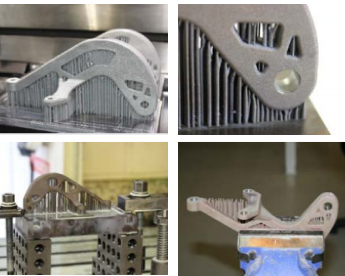
Figure 1 illustrates a typical example of a metal AM part with support structure.
1.2 Related work
The literature on support structures for AM is broad. Without attempting a comprehensive review, we present some background on support structure reduction, generation, and accessibility analysis. For a comprehensive review of the influence of support materials on design, planning, and post-processing for AM, see [5].
1.2.1 Reducing Support Structures
Support structures are sacrificial features that substantially add to manufacturing cost by increasing build time, material usage, and post-fabrication clean-up time. In metal AM, for instance, machine operation costs (energy, hardware, and labor) are about 63% of the total cost, material costs are about 18%, and post-processing costs are about 8%, on average [6]. Numerous researchers have investigated eliminating or reducing support materials for AM from different perspectives. Support structure layout is intimately coupled with the build direction. One of the most popular manufacturing planning strategies in AM is to choose a build direction that requires the least support material [7, 8, 9, 10, 11, 12, 13]. It is also possible to design the part itself in such a way that it requires the least amount of support while meeting other performance criteria. Multiple part design optimization approaches focus on eliminating support structures altogether by designing “self-supporting” shapes [14, 15]. Others optimize the design by considering support minimization in a trade-off with competing objective functions as a practical alternative [16, 17].
1.2.2 Generating Support Structures
Support structures must be designed to be accessible, heat-dissipating, lightweight and load-bearing [5]. Tree-like supports are a popular design for metal AM that can be manually generated through commercial packages such as MeshmixerTM. An automated approach for creating such supports was proposed in [18]. For powder-bed metal AM, a contact-free approach was developed in [19] where the support structure is not attached to the build part but effectively dissipates heat in the surrounding powder. For some polymer AM processes, it is also possible to use water-soluble support materials that can alleviate issues regarding support components that are hard-to-access or connected to thin features [20]. There are also recent efforts towards generating dissolvable supports for metal AM that exploit chemical and electrochemical stability between different metals [21]. However most of the metal AM processes are based on powder-bed fusion that are predominantly single-material.
1.2.3 Accessibility Analysis
Since it is not always possible to completely eliminate the support structures (or make them dissolvable, etc.), it must be ensured that all support components are accessible according to a specified post-process. Little attention has been paid to automating the accessibility analysis to remove supports, presumably because the interacting geometries are usually complex. While the ability to fabricate such complex shapes is one of AM’s great strengths, it makes post-process planning more challenging than, for instance, SM planning for traditional feature-based CAD models. When the tool assembly can translate and rotate at the same time, it tremendously adds to the complexity. Before addressing these problems, we briefly overview some of the challenges in accessibility analysis.
Accessibility analysis can be conveniently formulated in terms of the absence of interference at key locations on the intermediate part. The shape and degrees of freedom (DOF) of the moving tool substantially contribute to the difficulty of accessibility analysis, which is why many approaches try to simplify one or both of these inputs. For example, Spitz et al. [22] analyze the accessibility of coordinate measuring machines (CMM) under translation in terms of the free space (computed via a Minkowski sum) of part and CMM instrument. CMMs often have elongated stems to probe the part and therefore local accessibility analysis can be simplified in terms of visibility. In general, visibility analysis is used commonly as an approximation of accessibility analysis when tools can be abstracted into one or more rays (ignoring the thickness and shape) [23, 24, 25]. These approaches can be quite effective for a variety of problems, but generalize poorly when the interference is substantially influenced by tool geometry, as is the case with realistic tool assemblies.
Analysis of contact and interfering configurations is a fundamental problem in robot motion planning. Classical approaches focus on analytically describing the configuration space (-space) obstacle as the solution to polynomial equations that capture all possible contact interactions (e.g., vertex-face, face-face, etc.) between a polyhedral part/obstacle and tool/robot [26]. When the interacting shapes are complex non-convex polyhedra, exact computation of the space obstacle may require intersecting thousands of primitive patches. For general spatial motions, space mapping using analytical representations is typically restricted to relatively simple geometries. For a comprehensive review of space mapping, see [27].
Formulating motion planning problems in the configuration space of rigid motions is a classical approach [3] and has been studied extensively. The key insight is to transform the dynamic problem of planning the motion of a moving robot to the static problem of finding a path for a point in the free space. while the formalism is elegant, computing 6D free spaces has been considered a barrier to its practical implementation. Modern motion planners rely on sampling-based approaches such as probabilistic roadmaps [28, 29, 30, 31] to locally sample collision-free configurations and concatenate collision-free paths. This approach is quite successful, but requires explicitly specifying start and goal states for the motion planner. Identifying these start and goal states is itself a challenging spatial reasoning problem in support removal and other manufacturing planning applications.
To summarize, most approaches to accessibility analysis are based on simplifying either the interacting geometries, or the DOF available to the moving shape. In this paper, we make no such restrictions. We use the formalism of space modeling to formulate accessibility analysis for support removal, while using efficient computations of the free space by taking advantage of the known locations for finite and (presumably small) dislocation features. We show that the approach scales to practical situations involving complex part and tool geometries.
1.3 Contributions & Outline
We introduce an automatic spatial planning approach to identify a feasible and cost-effective sequence of support removal operations and a path to execute them.
Our approach relies on an explicit computation of the sampled (dynamically evolving) free space. It applies to parts, support structures, and tool assemblies of arbitrary shape, and multi-axis machines that have simultaneous access to translating and rotating DOF.
The paper is organized as follows:
In Section 2, we formulate the accessibility analysis problem in the space and outlines a recursive algorithm to identify a sequence in which the supports can be removed from a near-net shape. A key idea to make the computations on an evolving space tractable is to compute a maximal collection of removable supports at every “round” of the recursive algorithm, i.e., the collection of all supports whose every connection to the part is accessible in at least one orientation (Section 2.3). Brief introductions to space formulation and computations that are required to identify the maximal collection are provided in Sections 2.1 and 2.2. In particular, we model the set of accessible orientations at the connections of each support component to the part can be viewed as a ‘fiber’ in configuration space obtained from a lifting operation.
In Section 3 we present algorithms to plan for the sequence in which the supports of a given maximal collection are removed to optimize a cost function. We formulate this task as a traveling sales problem (TSP) [32] on a graph whose nodes are represented by the fibers and edges are weighted by the cost of traveling between them. Once a candidate plan is generated, we invoke a standard motion planning algorithm to compute collision-free tool-paths between fracture points to remove support components for the current round. The recursive algorithm is repeated until no support components remain.
Section 4 demonstrates nontrivial support removal on a nontrivial 3D bracket and 3D tool that has access to all six DOFs. Results are provided to underscore the practical implementation of the proposed algorithms.
2 Identifying Removable Supports
Removing supports by cutting off their contact regions with the part is an efficient alternative to machining the entire support material using a traditional milling process. For the latter, in the same way that one would remove material from a full raw stock [25, 33], one can clean out the support material by sweeping the tool within the support material over the continuum of accessible configurations. In our approach, we need only finite contact configurations to peel off the support components. This assumption is critical in our ability to efficiently compute the free space for an evolving near-net shape.
At the beginning, it is likely that only a subset of support components are removable in this manner with a given tool. Intuitively, we may imagine a forest of support components (e.g., columns) in a near-net shape, where the occluded columns are inaccessible until the columns along the periphery are removed.
Our approach uses known properties of the space of relative rigid transformations (detailed in Sections 2.1 and 2.2) to automatically identify the maximal collection of supports that are guaranteed to be removable from a near-net shape in an intermediate state. Briefly, the algorithm proceeds as follows: The space obstacle is computed explicitly and all contacting but non-colliding configurations of the tool are extracted. A support component is deemed removable iff all of its dislocation features are accessible through contact, meaning that there exists at least one configuration in the boundary of the space obstacle that corresponds to each dislocation feature. All removable support components are collected and designated for removal at the current “round” of the post-process plan. After removing this collection from the near-net shape, the obstacle reduces in size, more dislocation features become accessible, hence more support components become removable. The algorithm recursively identifies a sequence of removable supports that are peeled off by the cutting tool to finally converge to the desired part.
Note that this process is independent of the precise order and tool-path111For the moment, we take the existence of such a path for granted, which is not always the case. We return to this issue in Section 3.2. in which the collected support components of a given round are removed in practice. A manufacturability test is also encoded in the algorithm, which can identify early on if the near-net shape includes support components that are inherently unreachable even after removing the outer layers.
2.1 Constructing Configuration Space Obstacles
We formulate the support removal problem for dimensional shapes (typically, or ). Throughout the paper, we will use illustrations in 2D for building intuition, and show 3D results in Section 4.
Queries about the interference of a moving body (e.g., the tool assembly) against a stationary set of 3D obstacles (e.g., the near-net shape) are conceptualized as evaluating membership predicted against the space obstacle which partitions the space of relative rigid transformations into three disjoint regions representing free, contacting, and interfering configurations respectively. These regions correspond to the exterior, boundary, and interior of the space obstacle, respectively.
Constructing the obstacle is a critical step in our algorithm. Practical approaches use the fact that the particular group structure of (i.e., the Lie group of rigid transformations) allows it to be factored [34] into two simpler and lower-dimensional subgroups; namely, (for rotations) and (for translations). Hence, we can represent each rigid transformation as a tuple with and . In 2D, the former is a 2D vector while the latter is represented by a angle . In 3D, the former is a 3D vector while the latter can be represented in a number of different ways (e.g., orthogonal matrices, quaternions, axis-angle, Euler angles, etc.).

Let us denote a rotation of by by . Assuming that we are only dealing with solids (i.e., compact-regular seminalaytic sets in ) [35], the obstacle may be expressed as follows:
| (1) |
where represents the topological interior operator. The pointset is the topological closure of the translational space obstacle of with , i.e., the obstacle for a fixed orientation . It is well-known [36, 37, 38] that this pointset may be calculated in terms of a Minkowski sum.222The Minkowski sum of two pointsets is defined as . The space for all rotations is thus obtained by unifying the different translational spaces, each forming a slice of the obstacle. In practice, may be approximated as a stack of a finite number of slices, indexed by rotations sampled in . This approach is commonly used to calculate space obstacles for planar motions [38].
Notice that represents the closure of the translational space obstacle and its boundary, denoted by represents all the translations of the moving body (fir the fixed orientation) that cause surface contact but no volumetric interference with . The contact configurations are therefore obtained as:
| (2) |
The contact space is normally a lower-dimensional submanifold of , which makes its computation challenging. In practice, we approximate with a slightly “thickened” set, i.e., a narrow (but measurable) region surrounding the boundary of the space obstacle.
2.2 Querying Contact Configurations
Our approach uses the fact that the Minkowski sum of a pair of arbitrary solids corresponds to the support (i.e., superlevel set) of the convolution of the indicator functions of the two sets.333The indicator function of a pointset at a query point is defined as if and if . The advantage of this approach is that the convolution may be implemented in terms of Fourier transforms.444The Fourier transform of convolution is the same as the product of Fourier transforms. Hence, the convolution can be computed by two forward transforms, one pointwise multiplication in frequency domain, and an inverse transform. When the sets are sampled uniformly on a regular grid, the fast Fourier transform (FFT) provides an efficient and scalable implementation of each translational space obstacle (i.e, slice of ):
| (3) |
A configuration is inside the obstacle if the convolution does not vanish for at least one orientation . Note that the convolution of nonnegative functions is always nonnegative, hence the free space is defined implicitly by and equality test:
| (4) |
The convolution provides a field of overlap measure values between and over the translational space. In other words, measures the volume of intersection (if any) between and the moved body . Here, represents the Lebesgue measure (e.g., area for and volume for ) [39]. The queried configuration is in the space obstacle (resp. free space) iff this measure is greater than (resp. equal to) zero.
The contact space consists of configurations at which the overlap measure is critically zero, meaning that there exists an infinitesimal change to the configuration that can make it nonzero. To approximate in a computable fashion, we implicitly define an ‘contact’ space using the following predicate:
| (5) |
Using a small the threshold , one may assume that closely approximates from a measure-theoretic standpoint.
To summarize, if the slices are computed and stored beforehand (as a finite number of convolutions), it is possible to query the overlap measure in constant time at any sampled translation and rotation by interpolation against the stack of convolution fields. In particular, is numerically approximated as the set of all transformations where for some tolerable interference volume .
Figure 2 illustrates in 2D how the computed stack of convolutions for different slices for sampled rotations is used to classify a given tool configuration as free, contact, or colliding. In 3D, the same exact method applies, except that each convolution is a 3D field and the rotations are samples in 3D using any number of standard uniform or pseudo-uniform/random sampling methods [40].
Algorithm 1 describes a simple (and parallel) procedure to compute the contact space for a finite sample of orientations. The convolution is faster to compute on a regular sample of translations using uniform FFTs [36], which requires a regular axis-aligned sample (i.e., voxelization) of the part and rotated tool. The procedure takes which is very close to linear time in the number of sampled configurations . Note that this procedure is called only once per round of the recursive outer-loop (Algorithm 2). See the results in Fig. 8 of Section 4.
Note that storing the entire 6D set of space obstacle for 3D parts is not practical. However, the contact space , approximated by , is a sparse subset of the space that can be precomputed and queried later in constant-time.
2.3 Identifying Removable Support Components
In this Section, we reason about the tool assembly’s free space to automatically construct a maximal collection of removable support components. This collection is defined as the set of all support components that may be removed by the tool assembly without interfering with the near-net shape, except by the tool tip at the fracture points.
Let denote the part and support structure, respectively, which only contact over their common boundary denoted by . The initial near-net shape is obtained as .
The support structure commonly consists of many connected components (called hereafter support components):
| (6) |
where stands for the component (). We assume that a given support component is removable with a given cutting tool if the tip of the tool can access and fracture all contact regions between the support component and the part boundary in one or more collision-free configurations, i.e., positions and orientations of the tool at which the tool does not interfere with the part or other support components. The contact region is also decomposed into its connected components (hereafter called dislocation features):
| (7) |
where stands for the feature (). Note that the indexing scheme for (6) and (7) are different because every support component is connected to the part via two or more dislocation features hence . The nomenclature is illustrated in Fig. 3 for a 2D example.
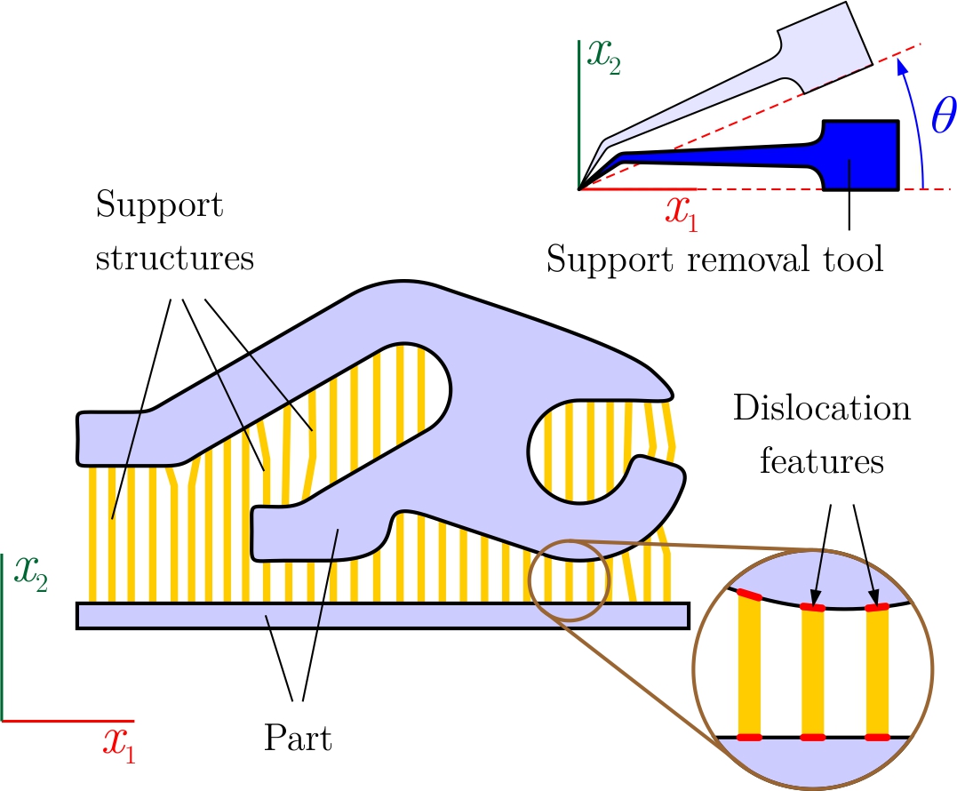
Support structures are typically designed to have small contact regions with the part’s surface to enable easier fracturing and removal and to minimize surface roughness after removal. Note that sometimes support components are constructed from one location on the part to another, but it is preferred that they are constructed connect the part’s surface to the machine’s base plate. Moreover, one support component can be connected to the part at multiple locations, e.g., when they are designed to branch out from a main trunk. To accommodate the most general condition, we do not make any simplifying assumption on the shape, connectivity, number, or layout of support components and their dislocation features.
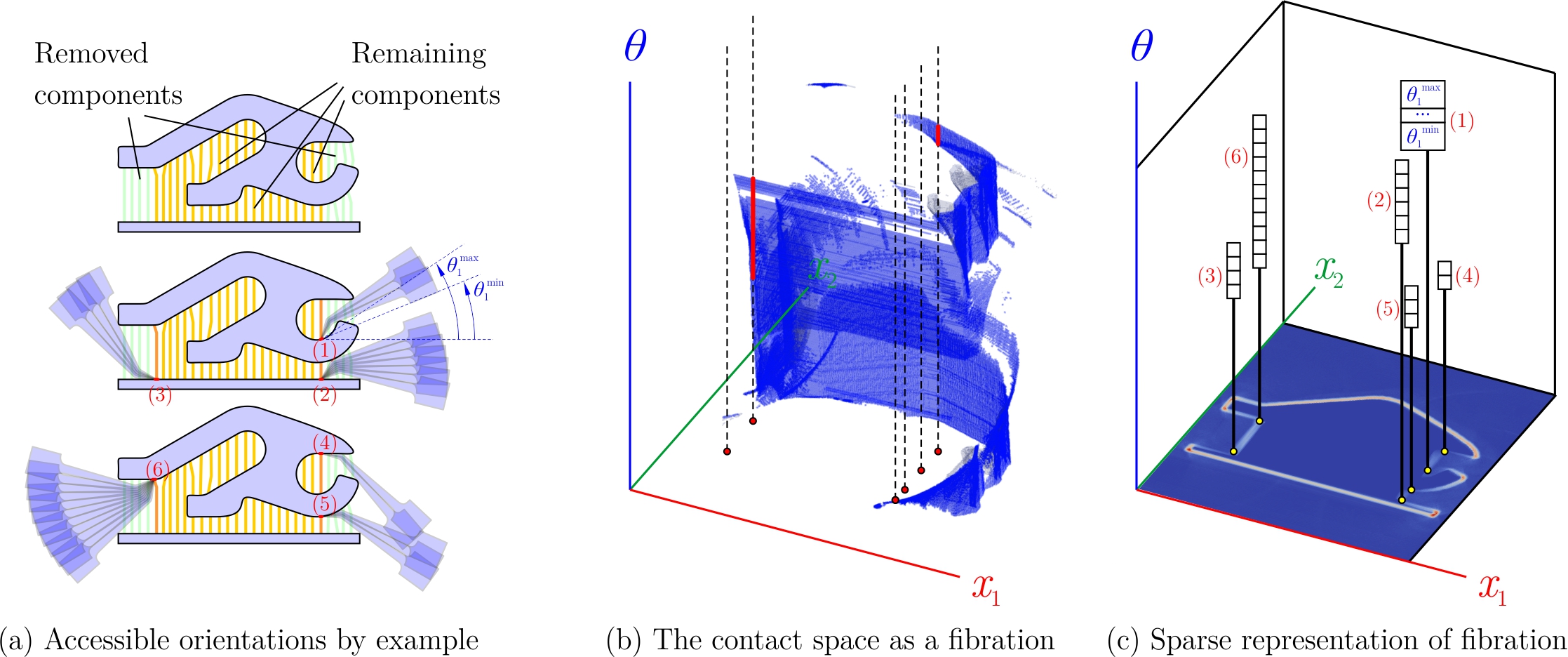
Let us position the tool in its original configuration in such a way that the cutter tip (or some point on the cutting surface) coincides with the origin of the coordinate system used as a reference frame to quantify the rigid transformations of the tool assembly with respect to the near-net shape at a given round. This choice ensures that a transformation brings the tool’s cutter (and not any other point on the tool) to the point in the Euclidean space where the near-net shape resides. Although this choice is not necessary from a theoretical standpoint, it simplifies the accessibility analysis by querying the pre-computed space map.
In a dimensional space, the tool can operate with all degrees of freedom, of which are for rotations and the remaining are for translations. We can define projections from to and , respectively, that map every rigid transformation to and :
| (8) |
Notice that the second projection depends on the earlier choice of origin. Clearly, these maps are not invertible as functions. Nonetheless, we can define liftings that take every and to a subspace of :555 denotes the powerset of a set .
| (9) |
By extension, we can define set functions; for example, such that assigns a copy of the entire to every point :
| (10) |
Given a dislocation feature , the set of all configurations at which it can be touched by the tool tip can be obtained in terms of the above projection/lifting maps:
| (11) |
In other words, every dislocation feature is lifted to the space by pairing it with all possible orientations. The pairing results in the set of all possible configurations that bring the tool tip to the dislocation feature (at different orientations). Among them, the ones that are contained within the contact space are collision-free, hence they represent the set of all accessible configurations. Hereafter, we refer to as the contact fiber for the dislocation feature. Once again, for computational purposes, we can approximate the contact fibers via fibers, using the measurable contact region:
| (12) |
In practice, the dislocation features are small enough to assume that touching any point on their circumference is sufficient to fracture it. As a result, we can simply project the fiber from to to collect all accessible orientations at all positions within the feature:
| (13) |
whose fiber approximations are given as expected by:
| (14) |
Figure 4 illustrates the fibers for a 2D example in which the dislocation features are contracted to points. From an algorithmic perspective, each fiber can be hashed into a list of sampled orientations anchored at a different dislocation features. A dislocation feature is accessible iff its fiber is nonempty. As a result, we observe that a given support component is removable iff every one of its dislocation features has a nonempty fiber.
Algorithm 2 describes the procedure for finding the contact fibers in a single round of recursive support removal planning. The procedure performs queries on every one of the convolution fields precomputed and stored for sampled orientations, resulting in a total of queries—each convolution-read taking constant time. This analysis assumes that we need queries per each dislocation feature, because each feature is sampled by one or at most a few point(s), which is reasonable. Every orientation that is accessible is pushed into a stack that represents the fiber for the queried feature.
Note that before performing the queries, we can shortlist the features rapidly to accessible ones by projecting the contact space to the Euclidean space (i.e., losing orientation information) and finding its common points with the dislocation features:
| (15) |
This means that there exists at least one point in the dislocation feature that belongs to the projected contact space. The projection ensures that there exists at least one non-colliding orientation at which the said point is accessible. Note that the projected contact space can be obtained by unifying the translational contact spaces for different orientations:
| (16) |
Once again, the contact space can be approximated by the contact criterion. As such, the above early test for accessibility can be rapidly computed by summing up the indicator functions of the translational contact spaces, which, in turn, are obtained as the interval level set of the convolution fields for different slices. The resulting pointset is a single field over the space with a narrow support, containing all positions in the vicinity of the near-net shape’s boundary that can be accessed by at least one orientation. For every point , we accumulate the convolution value over slices for which the condition holds. This incurs no additional computation cost because as the convolutions are precomputed, their interval level sets can be extracted and accumulated on-the-fly. The result is a field with a narrow-band support over the space that quantifies non-colliding orientations of a given point. A 2D example of the accumulated and projected field of contact measures is illustrated in Fig. 4 (c) (base field). A dislocation feature is accessible iff it has at least one point at which this function is nonzero. Note that this early test counts the accessible orientations; however, it does not tell us which orientations (i.e., the fiber).
2.4 Recursive Support Removal Rounds
It is likely that multiple support components are removable from the near-net shape at a given intermediate state. Intuitively, every round of the recursive algorithm peels off all removable components to expose a new set of components. The process is repeated until either all supports are removed, or the part is deemed non-manufacturable because some supports are inaccessible. See the results in Fig. 10 of Section 4.
At round of the support removal algorithm,666Note that superscripts here are used to indicate the rounds of the algorithm, and should not be confused with the subscripts used earlier to indicate connected components. the near-net shape is with initial conditions and . Both and are monotonically reduced (in terms of set containment) from one round to the next, i.e., and .
Let represent the indices for the maximal collection of removal supports at a given round, i.e., for every , the support component is removable at round. If represents the indices of the dislocation features for the same support component, then iff for every , the fiber is nonempty, i.e.,
| (17) |
The remaining support for the next round is computed as: . The algorithm continues until either of two termination criteria can happen:
-
1.
, i.e., , which implies successful removal of the entire support; or
-
2.
and which indicates that the remaining support components cannot be reached.
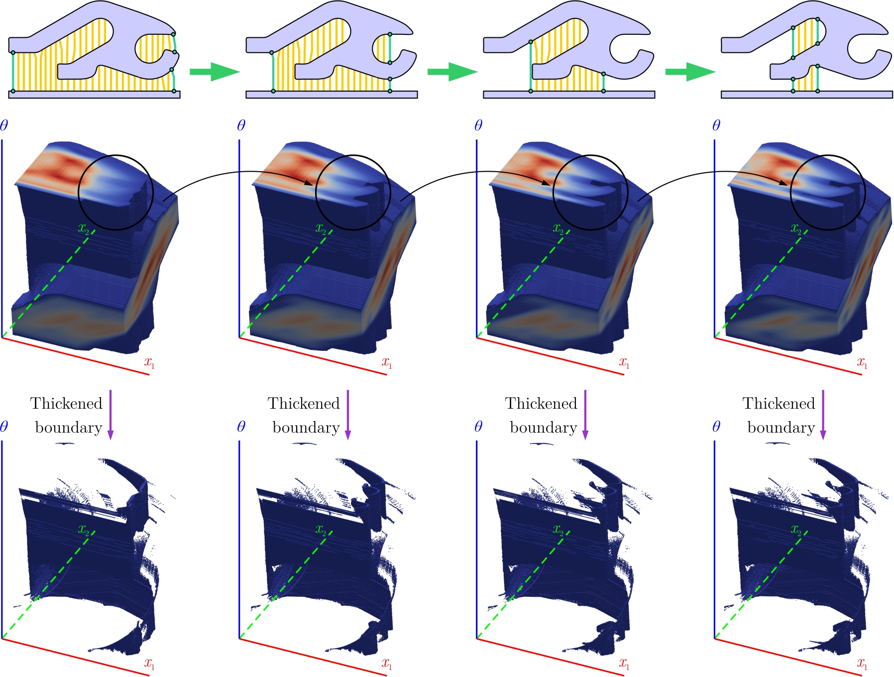
Figure 5 illustrates a few rounds of recursive support removal for a 2D example. The space obstacle and contact space change as more supports are removed.
2.5 Necessary and Sufficient Conditions
Algorithm 3 illustrates an implementation of the recursive algorithm. All potentially accessible support components are identified by checking if for every for every remaining support component . If at any given round, no supports are identified for removal, the algorithm returns a failure message indicating that the support structure is inherently not removable. In other words, this test provides a necessary condition for the AM post-process to be feasible. While the test is quite useful in finding the order in which the support components should be fractured, it does not provide a sufficient condition. For example, the test does account for the situations where there is a collision-free final configuration to touch the dislocation feature, but there may not exist a collision-free path in the space that brings the tool from its initial configuration to the final pose. This situation can happen if the free space is not path-connected, and the initial and final configurations are located in different connected components. Figure 6 illustrates an example of a false-positive. Such scenarios are rare if the support structure is designed properly.
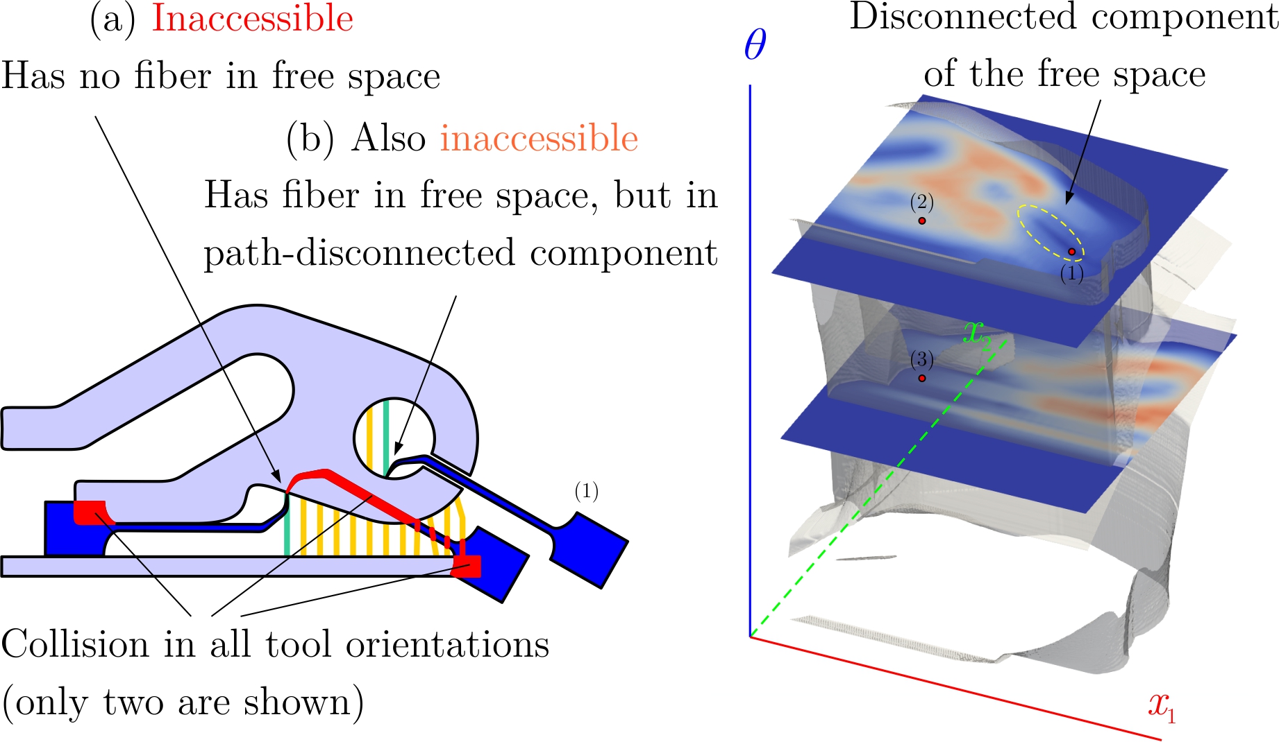
Although analyzing path-connectedness is important, is high-dimensional for and the free space topology can be highly complex. As opposed to reasoning about the topology, we can use a sampling-based motion planner (e.g., based on probabilistic roadmaps [28, 29, 30, 31]) to find a collision-free path from a reasonable starting configuration in to at least one configuration in the fiber.
3 Support Removal Planning
In Section 2.3 we have shown how an ordered sequence of the indices for maximal collections of removable support components may be computed. Each represents a collection of support components that can be removed in any order as long as all the support components preceding them in the sequence have been removed in earlier rounds of the algorithm.
In this section, we describe approaches to plan for the removal of the support components within each group to reduce a cost function. At the outset, we observe that any two collections and may be processed independently, because their space obstacles are defined with respect to distinct near-net shapes . In other words, the order in which the support components are removed at one round does not affect the order for another round. As far as we assume an additive cost function, we may solve the planning problem for different rounds in parallel.
3.1 A Traveling Salesman Formulation
Given a near-net shape , the tool assembly , and a sub-collection of support components consisting of , removing all components amounts to finding a collision-free path in the space that moves the tool tip to all dislocation features that connect the said support components to the part. These dislocation features are given by . The accessible configurations for every one of them is given by a fiber; hence, the planning problem can be formulated as finding a path in the space that visits all fibers one after another. It suffices for the path to intersect with every fiber at least once, meaning that the tool touches the dislocation feature in at least one accessible orientation.
The cost function for a candidate path can be defined in several plausible ways. If we use machining time as the criteria and assume an almost constant speed in the space, the path length in the space may serve as a cost function. However, it is likely in practice to have different cost factors associated with translational and rotational machine DOF. Here are two extreme cases:
-
•
If we have a axis machine that needs re-fixturing for every change of orientation, moving in the rotation space is significantly costlier than moving in the translational space. In this case, the cost function is to minimize the total number of orientations needed to visit all fibers. Using the mental picture in Fig. 4, we may formulate this problem as finding the minimal number of slices to “cut” the given set of fibers, where each fiber is cut at least once.
-
•
If for any reason changing orientations is cheaper, the problem is dramatically simplified. We can formulate the path planning conveniently in the Euclidean space, especially since every fiber is projected to a small region (i.e., dislocation feature) which can be approximated by a point. The translational distance between the points, obtained by measuring the curve length in the space serves as a cost function.
Consider a pair of configurations and , each selected from a different fiber that needs to be visited at a given round, i.e., , , , and . The curve-length of a geodesic in the space the connects these configurations is given by the Riemannian distance in which stands for the standard logarithm function,777The logarithm function on a Lie group defines a local coordinate system over a neighborhood by mapping the group elements to the Lie algebra (i.e., the tangent vector space) [34]. which can be computed directly on the matrix representation of the relative transformation , and is the Frobenius (i.e., ) norm. The minimum distance between all pairs of configurations from the two fibers is a lower-bound to the length of any curve segment that connects the two fibers in the space:
| (18) |
The above distance function is well-defined for every pair of fibers (as a whole). We can construct an undirected complete graph that has vertices, one for each fiber and an additional one for the reference configuration from which the tool assembly starts moving and returns to after removing supports. We can associate the above distance function with every edge, noting that it provides an admissible heuristic to approximate the actual cost function before motion planning. This is important for computational tractability of the algorithm.
Finding the shortest path to visit all fibers (i.e., vertices or “cities”) at least once is thus formulated as a traveling salesman problem (TSP) [32]. Our goal is to create a Hamiltonian cycle (a tour) with minimum cost, obtained by adding the costs of individual edges on the graph, starting and ending at the reference vertex.
The TSP is NP-complete, but we may use an approximation algorithm [41] if the cost-function is a proper metric. Distance functions defined via minima of pairwise distances as in (18) do not normally qualify because they may not satisfy reflexivity and triangle inequality, even though the pairwise distance itself is a metric, as in the case of the Riemannian metric. The more appropriate formulation in this case would be to associate every configuration (as opposed to every fiber) with a graph vertex, use the pairwise Riemannian distance, which is a proper metric, as the cost associated with every edge, and solve a more complex generalization of TSP in which every group of cities (i.e., fibers) has to be visited at least once.
Fortunately, if the dislocation features are small and ignore the cost of moving along a single fiber—i.e., in-place rotations at a given dislocation feature before moving to the next feature—we can still formulate and solve the problem as a TSP. Using the approximation algorithm in [41], we may assert that the cost of the tour is no more than twice that of the minimum spanning tree’s weight. The algorithm will find a sequence of graph vertices (configurations) that are visited exactly once. The vertex sequence then delineates the start and goal configurations for a sequence of motion planning problems that can be solved by a standard motion planner. Note that the contact fiber configurations will include minimal interference with (corresponding to cutting) the supports. The start and end configurations are locally perturbed to ensure a collision free path can be found.
3.2 Motion Planning over the Fibration
We use the Open Motion Planning Library (OMPL) [42] to compute collision-free paths to go from one fiber to the next in the sequence prescribed by the TSP solution. The start and goal configurations on every fiber are selected using a greedy policy as follows: For the first configuration, we start from a given initial pose of the tool. For every fiber that is visited next in the sequence, we select the configuration on the fiber that is the nearest (in terms of the Riemannian metric) to the preceding configuration selected on the previously visited fiber in the sequence.
As discussed earlier, there may be cases when the free space is not path-connected. In such cases, even after successful determination of removable support components with nonempty fibers (via Algorithm 3) and ordering them via TSP solution, the motion planner may not be able to find a collision-free path to a dislocation feature.
We note that having explicitly computed could help find collision-free paths by overloading the collision checker of the motion planner with a constant-time membership query against . However, as pointed out in Section 2.1, it is impractical to store an explicit representation of the entire . The stored contact space approximated by represents a boundary of the space obstacle under fairly general conditions, hence can be used as a substitute.
However, membership queries against boundary representations might be more time-consuming than highly-optimized collision detection algorithms. Moreover, once the start and goal configurations are known, motion planning via probabilistic roadmaps is hard to beat in terms of both efficiency and accuracy. In particular, the accuracy of membership queries against precomputed (even when it is possible, e.g., in 2D) is limited by the rasterization resolution. We can use a conservative policy, meaning that the discretized 3D models are chosen to strictly contain the “exact” CAD models to ensure that the approximation to obtained via discrete convolutions also contains the exact space obstacle. While this is safe policy as it overestimates collisions, it commonly results in false-positives, especially at contact configurations, e.g., detecting a collision when the tool is touching the dislocation feature while there is none.
The convolution field is a fast and effective approach to computing the collision measures for a large number of configurations at once—unlike collision detection on B-reps, which is better suited for a single configuration at-a-time. It is critical in our ability to sift through a large number of dislocation features and decide their accessibility quickly at every round of the recursion with evolving near-net shape. However, after the accessible configurations, motion planning can be done with collision detection between the master CAD models (e.g., B-reps) with a much higher precision than that of rasterized models.
4 Results
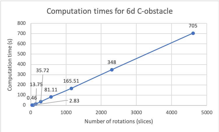
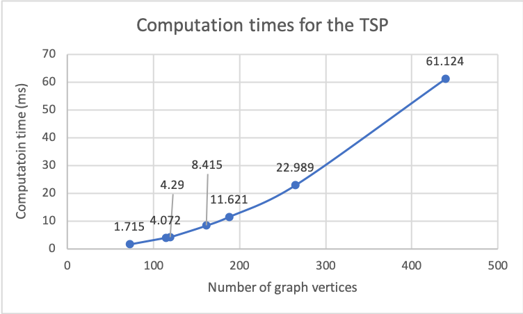

.
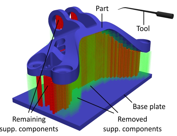
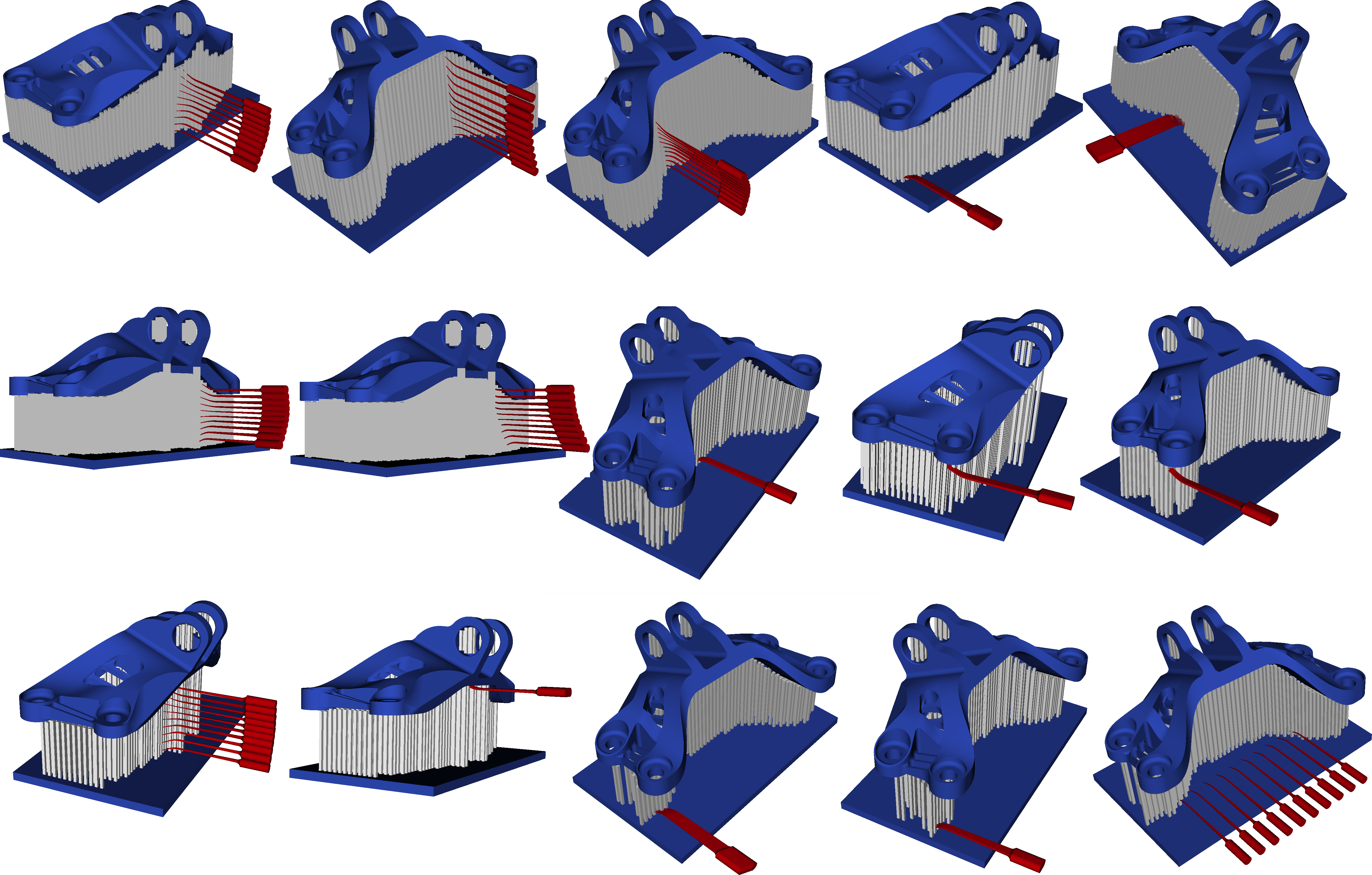
We demonstrate the approach using an illustrative 3D example. A near-net shape along with a cutting tool to remove supports at dislocation features is shown in Fig. 7.
We assume that the part is fixtured properly (not shown here, similarly to Fig. 1) such that the removal sequence of the support components does not impact its stability.
At every round, Algorithm 3 identifies the outer layer of supports that can be peeled off, using FFT-based convolution (Sections 2.1 and 2.2) as illustrated in Fig. 10. For each layer, solving the TSP on the graph of fibers (Section 3) gives a sequence of configurations to visit, while asserting all of them will contact a distinct dislocation feature without collision.
5 Conclusion
Support removal is an important post-processing step for AM and is often a bottleneck for manufacturability. We have shown an automated solution to identifying and removing support materials in an AM part, by exploiting the properties of the space obstacle, free space, and contact space obtained as their shared boundary. The contact space is extracted as an interval level set of a sparse field that is precomputed and queried during a recursive algorithm to peel off removable supports. The approach does not make assumptions on part, tool, or support structure geometries, or on the DOF with which a tool can move.
Several improvements to this paper are possible. The computations are highly parallelizable and offer opportunities for more efficient implementation. Furthermore, uniform sampling of the rotation space for space computations can be improved by choosing rotations based on more specific manufacturing constraints.
As opposed to explicitly computing space obstacles and finding goal states for a motion planner, one may directly find collision-free paths between neighboring dislocation features by locally sampling configurations and invoking rapid collision-checkers. This is similar to the probabilistic roadmap approach to path planning [28, 29, 30, 31]. Nonetheless, this paper demonstrates that explicit calculation of 6D space maps should not be considered as an impediment to solving practical mechanical design and manufacturing problems. We hope that it inspires researchers to apply these methods to other practical problems in which the specific properties of the application can be leveraged to make space computations tractable.
Last but not least, while this paper’s focus has been kinematics and spatial planning aspects, there are many unsolved problems with regard to the physics of support removal (e.g., mechanics of the fracture process) that have been ignored and need to be considered in practice.
Acknowledgement
This research was developed with funding from the Defense Advanced Research Projects Agency (DARPA). The views, opinions and/or findings expressed are those of the authors and should not be interpreted as representing the official views or policies of the Department of Defense or U.S. Government.
References
- [1] T. Yamazaki, Development of a hybrid multi-tasking machine tool: Integration of additive manufacturing technology with CNC machining, Procedia CIRP 42 (2016) 81–86.
- [2] M. Behandish, S. Nelaturi, J. de Kleer, Automated process planning for hybrid manufacturing, Computer-Aided Design 102 (2018) 115–127.
- [3] T. Lozano-Perez, Spatial planning: A configuration space approach, IEEE Transactions on Computers C-32 (2) (1983) 108–120. doi:10.1109/TC.1983.1676196.
- [4] K. Hamilton, Planning, preparing and producing: Walking the tightrope between additive and subtractive manufacturing, in: Metal AM, Vol. 2, Inovar Communications, Ltd., 2016, pp. 39–56.
- [5] J. Jiang, X. Xu, J. Stringer, Support structures for additive manufacturing: A review, Journal of Manufacturing and Materials Processing 2 (4) (2018) 64.
- [6] D. S. Thomas, S. W. Gilbert, Costs and cost effectiveness of additive manufacturing, NIST Special Publication 1176 (2014) 12.
- [7] F. Nezhad, A. S.and Barazandeh, A. R. Rahimi, M. Vatani, Pareto-based optimization of part orientation in stereolithography, Proceedings of the Institution of Mechanical Engineers, Part B: Journal of Engineering Manufacture 224 (10) (2010) 1591–1598.
- [8] P. Das, R. Chandran, R. Samant, S. Anand, Optimum part build orientation in additive manufacturing for minimizing part errors and support structures, Procedia Manufacturing 1 (2015) 343–354.
- [9] R. Paul, S. Anand, Optimization of layered manufacturing process for reducing form errors with minimal support structures, Journal of Manufacturing Systems 36 (2015) 231–243.
- [10] B. Ezair, F. Massarwi, G. Elber, Orientation analysis of 3D objects toward minimal support volume in 3D-printing, Computers & Graphics 51 (2015) 117–124.
- [11] H. D. Morgan, J. A. Cherry, S. Jonnalagadda, D. Ewing, J. Sienz, Part orientation optimisation for the additive layer manufacture of metal components, The International Journal of Advanced Manufacturing Technology 86 (5-8) (2016) 1679–1687.
- [12] D. Coupek, J. Friedrich, D. Battran, O. Riedel, Reduction of support structures and building time by optimized path planning algorithms in multi-axis additive manufacturing, Procedia CIRP 67 (2018) 221–226.
- [13] A. Hehr, J. Wenning, K. Terrani, S. S. Babu, M. Norfolk, Five-axis ultrasonic additive manufacturing for nuclear component manufacture, JOM 69 (3) (2017) 485–490.
- [14] A. T. Gaynor, J. K. Guest, Topology optimization considering overhang constraints: Eliminating sacrificial support material in additive manufacturing through design, Structural and Multidisciplinary Optimization 54 (5) (2016) 1157–1172.
- [15] M. Langelaar, Topology optimization of 3D self-supporting structures for additive manufacturing, Additive Manufacturing 12 (2016) 60–70.
- [16] A. M. Mirzendehdel, K. Suresh, Support structure constrained topology optimization for additive manufacturing, Computer-Aided Design 81 (2016) 1–13.
- [17] X. Qian, Undercut and overhang angle control in topology optimization: A density gradient based integral approach, International Journal for Numerical Methods in Engineering 111 (3) (2017) 247–272.
- [18] J. Vanek, J. A. G. Galicia, B. Benes, Clever support: Efficient support structure generation for digital fabrication, in: Computer Graphics Forum, Vol. 33, Wiley Online Library, 2014, pp. 117–125.
- [19] K. Cooper, P. Steele, B. Cheng, K. Chou, Contact-free support structures for part overhangs in powder-bed metal additive manufacturing, Inventions 3 (1) (2018) 2.
- [20] F. Ni, G. Wang, H. Zhao, Fabrication of water-soluble poly (vinyl alcohol)-based composites with improved thermal behavior for potential three-dimensional printing application, Journal of Applied Polymer Science 134 (24).
- [21] O. J. Hildreth, A. R. Nassar, K. R. Chasse, T. W. Simpson, Dissolvable metal supports for 3D direct metal printing, 3D Printing and Additive Manufacturing 3 (2) (2016) 90–97.
- [22] S. N. Spitz, A. J. Spyridi, A. A. G. Requicha, Accessibility analysis for planning of dimensional inspection with coordinate measuring machines, IEEE Transactions on Robotics and Automation 15 (1998) 714–727.
- [23] A. Limaiem, H. A. EIMaraghy, Integrated accessibility analysis and measurement operations sequencing for CMMs, Journal of Manufacturing Systems 19 (2) (2000) 83–93.
- [24] D. Arbelaez, M. C. Avila, A. Krishnamurthy, W. Li, Y. Yasui, D. Dornfeld, S. McMains, Cleanability of mechanical components, Tech. rep., University of California, Berkeley (2008).
- [25] S. Nelaturi, G. Burton, C. Fritz, T. Kurtoglu, Automatic spatial planning for machining operations, in: Proceedings of the 2015 IEEE International Conference on Automation Science and Engineering (CASE’2015), 2015, pp. 677–682. doi:10.1109/CoASE.2015.7294158.
- [26] J. Canny, The complexity of robot motion planning, Acm doctoral dissertation awards, ACM (1988).
- [27] K. D. Wise, A. Bowyer, A survey of global configuration-space mapping techniques for a single robot in a static environment, The International Journal of Robotics Research 19 (8) (2000) 762–779.
- [28] L. Kavraki, P. Svestka, M. H. Overmars, Probabilistic Roadmaps for Path Planning in High-Dimensional Configuration Spaces, Vol. 1994, IEEE, 1994.
- [29] L. E. Kavraki, P. Svestka, J. C. Latombe, M. H. Overmars, Probabilistic roadmaps for path planning in high-dimensional configuration spaces, IEEE Transactions on Robotics and Automation 12 (4) (1996) 566–580.
- [30] D. Hsu, L. Kavraki, J. Latombe, R. Motwani, S. Sorkin, On finding narrow passages with probabilistic roadmap planners, in: Proceedings of the International Workshop on Algorithmic Foundations of Robotics (WAFR), Vol. 1998, ACM, 1998.
- [31] V. Boor, M. H. Overmars, A. F. van der Stappen, The Gaussian sampling strategy for probabilistic roadmap planners, in: IEEE International Conference on Robotics and Automation (ICRA’1999), Vol. 2, IEEE, 1999, pp. 1018–1023.
- [32] S. Lin, Computer solutions of the traveling salesman problem, Bell System Technical Journal 44 (10) (1965) 2245–2269.
- [33] M. Behandish, S. Nelaturi, M. Allard, Automated process planning for turning: A feature-free approach, in: Advances in Manufacturing Techonology XXXII, Advances in Transdisciplinary Engineering Series, Volume 8, 2018, pp. 45–50, proceedings of the International Conference on Manufacturing Researh (ICMR’2018).
- [34] J. M. Selig, Geometrical Fundamentals of Robotics, Springer-Verlag New York, 2005.
- [35] A. A. G. Requicha, Representations for rigid solids: Theory, methods, and systems, ACM Computing Surveys (CSUR) 12 (4) (1980) 437–464.
- [36] L. Kavraki, Computation of configuration-space obstacles using the fast Fourier transform, IEEE Transactions on Robotics and Automation 11 (3) (1995) 408–413.
- [37] A. E. Middleditch, Application of vector sum operator, Computer-Aided Design 20 (4) (1988) 183–188.
- [38] J. C. Latombe, Robot Motion Planning, Vol. 124, Springer Science & Business Media, 2012.
- [39] M. Lysenko, S. Nelaturi, V. Shapiro, Group morphology with convolution algebras, in: Proceedings of the 14th ACM Symposium on Solid and Physical Modeling (SMP’2010), ACM, 2010, pp. 11–22.
- [40] A. Yershova, S. Jain, S. LaValle, J. Mitchell, Generating uniform incremental grids on using the Hopf fibration, The International Journal of Robotics Research 29 (7) (2010) 801.
- [41] T. H. Cormen, C. E. Leiserson, R. L. Rivest, C. Stein, Introduction to Algorithms, MIT press, 2009.
- [42] I. A. Şucan, M. Moll, L. E. Kavraki, The Open Motion Planning Library, IEEE Robotics & Automation Magazine 19 (4) (2012) 72–82, http://ompl.kavrakilab.org. doi:10.1109/MRA.2012.2205651.