Analog Weights in ReRAM DNN Accelerators
Abstract
Artificial neural networks have become ubiquitous in modern life, which has triggered the emergence of a new class of application specific integrated circuits for their acceleration. ReRAM-based accelerators have gained significant traction due to their ability to leverage in-memory computations. In a crossbar structure, they can perform multiply-and-accumulate operations more efficiently than standard CMOS logic. By virtue of being resistive switches, ReRAM switches can only reliably store one of two states. This is a severe limitation on the range of values in a computational kernel. This paper presents a novel scheme in alleviating the single-bit-per-device restriction by exploiting frequency dependence of v-i plane hysteresis, and assigning kernel information not only to the device conductance but also partially distributing it to the frequency of a time-varying input.
We show this approach reduces average power consumption for a single crossbar convolution by up to a factor of 16 for an unsigned 8-bit input image, where each convolutional process consumes a worst-case of 1.1mW, and reduces area by a factor of 8, without reducing accuracy to the level of binarized neural networks. This presents a massive saving in computing cost when there are many simultaneous in-situ multiply-and-accumulate processes occurring across different crossbars.
Index Terms:
accelerator, analog, memristor, neural network, ReRAMI Introduction
The recent rise of IoT and the proliferation of cheap sensors has brought with it an explosion of data requiring inference. Inference hardware is currently a bottleneck in the data processing pipeline, spawning the development of application-specific integrated circuits (ASICs) also known as inference accelerators. The dominant computation during inference in deep neural networks (DNNs) and convolutional neural networks (CNNs) is dot-product multiplication, which translates simply to the multiply-and-accumulate (MAC) operation. This can be expensive to implement and requires numerous logic gates.
Memristive crossbar arrays simplify the hardware mapping of DNN algorithms in two ways: 1) they require less devices per MAC operation; only one single memristor is needed per multiply operation as opposed to potentially over 40 transistors in CMOS for a binary multiplier, and 2) decreasing the physical distance between memory (kernel storage) and computation, thus reducing delay and vulnerability to signal degradation. The use of memristor-based AI accelerators show promise as they enable computation-in-memory architecture for data-intensive applications.
Computational kernels in DNNs require more than two bits per element for high accuracy, but multi-bit memristive crossbars remain highly experimental. This brief presents a novel frequency-dependent scheme to produce analog-valued weights from a single-bit memristor, thus increasing accuracy, and removing the need to distribute computation across various bit-lines which reduces current sneak path and line resistance effects. The use of a DC driving voltage (for inference), as often implicated, is unfeasible as the v-i curve converges to a single-valued function and behaves as a non-linear resistor [1]. This eliminates any switching effect, and necessitates a time-varying input to maintain bi-valued hysteresis which is poorly addressed in the literature. Furthermore, kernels and weights conventionally take on any number of values – not just ‘on’ and ‘off’.
By exploiting frequency dependency of memristor conductance, we show it is possible to map a continuous range of weights that are assignable to memristors. The weights are expressed as not only a function of an input voltage pulse (as has been demonstrated in the past) but also as a function of input frequency. Section II describes crossbar operation in DNNs and CNNs to generate the MAC operation, and by extension, 2D convolution. Section III presents a look-up table that maps device conductances to driving frequency, and Section IV provides the derivation of limitations on the driving input. These analytical results are then used in Section V for experimental verification, where we apply our proposed method to a noisy 128128 input image through a Gaussian convolution filter for image smoothing. Provided that our method is capable of convolutional image processing, then it will also be able to perform inference in DNNs. Discussions that follow show that the presented frequency-dependent method can reduce crossbar area down to 12.5% of the original size for an unsigned 8-bit image, with associated power savings that are also characterized and compared against other state-of-the-art methods of image filtering in crossbars. This is all performed without the need to reduce the system down to a binarized NN, which is associated with sacrificing accuracy in more complex processes [2]. Furthermore, this scheme also enables bit-lines of crossbars to be allocated to other tasks such as the processing of different channels, which thus speeds up the pipeline.
II Crossbar Operation
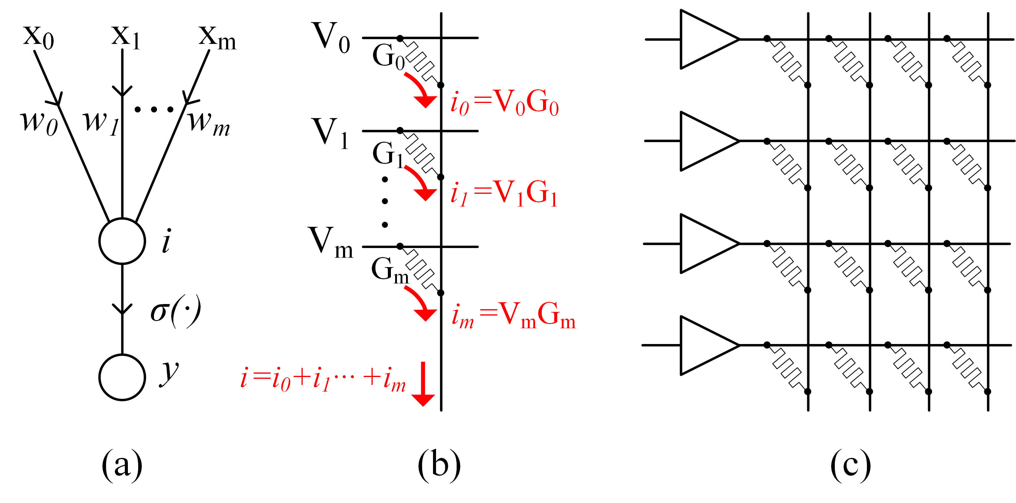
As shown in Fig. 1(a), a single neuron in an artificial neural network accepts inputs with signals through and weights through . The output of a neuron is represented by:
| (1) |
where is some activation function, in this case the sigmoid function. The term in parentheses is a MAC operation, which can be computed using a resistive switching crossbar [3, 4, 5, 6, 7, 8, 9, 10, 11] by mapping weight to conductances , and inputs to voltages . The total current at the output of each bit-line is a summation of the current that each memristor within a single column draws from its corresponding input. The summation of current from Fig. 1(b) that is passed through an activation unit is congruous to from (1). The mapping from the artificial neuron to crossbar architecture can be discerned on inspection of Fig. 1, in mapping neural inspired image processing into hardware [12, 13].
Weights are pre-trained to take on any range of values, whereas is typically restricted to either a high or low value. In the following section, we formalize a way to circumvent this limitation without the use of multi-level memristors by using a half-sine pulse as input, and varying the width (i.e., frequency content) of the pulse.
III Mapping Weight to Conductance
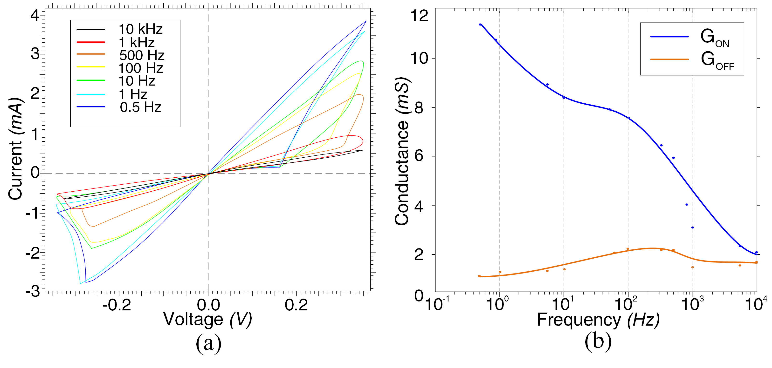
The relationship between frequency and conductance is device-dependent. In this work we use a Ag-chalcogenide memristor made up of GeSeSn-W [14] to generate an experimentally verified look-up table. This table is used to select appropriate frequencies for a given conductance (or equivalently, kernel weight). The v-i characteristic curves are shown in Fig. 2(a), conductance is plotted as a function of frequency in Fig. 2(b), and tabulated in Table I.111The plots display averaged values across 5 trials at each given frequency. Device reliability will affect the range of weights that can be represented.
| Freq. [Hz] | [mS] | [mS] |
|---|---|---|
| 10k | 1.71 | 2.10 |
| 1k | 1.49 | 3.13 |
| 750 | 1.56 | 4.20 |
| 500 | 2.20 | 5.97 |
| 100 | 2.26 | 7.60 |
| 10 | 1.4 | 8.40 |
| 1 | 1.32 | 10.8 |
| 0.5 | 1.15 | 11.4 |
Furthermore, Fig. 2(b) depicts the convergence of and as driving frequency increases, i.e., above a certain frequency the v-i characteristic curve degenerates to a single-valued monotonically increasing function. Note that some conductances are repeated across varying frequencies. For example, a frequency of 480 Hz results in of approximately 2.10mS, and a frequency of 10k Hz results in an approximately identical value of . In such duplicative cases there are multiple choices of frequency: a higher frequency will generate faster output, and a lower frequency will dissipate less power. Whether to prioritize speed or power is determined by user requirements. With the frequency-dependent look-up table generated, we must now consider the necessary conditions on amplitude and phase conditions of the input to successfully perform convolutional operations.
IV Experimental Setup
The input voltage must be time-varying to ensure a bi-valued conductance function. Here, we use half-sine pulses of duration . Graphically, there is no switching between v-i hysteresis branches of resistance during inference – only partial switching by altering the gradient of the low resistance branch.
The use of varying frequencies across inputs results in timing mismatch. This is qualitatively depicted in Fig. 3 for demonstration purposes, where is the period of the input, is the period of the widest pulse, is the phase-shift of the input and can be calculated using (1) without the activation, and corresponds to the required sum of current amplitudes for MAC computation.
By reference to Fig. 3, without a phase-shift of , the peaks of and do not align, which results in current output whose peak does not reflect the MAC operation. The maximum values of each row input must occur simultaneously in order for the peak value of output current to perform MAC. This requires a phase-shift to be introduced in order to align the peak of all row inputs with the maximum period used. In this case, as per Table I, and occurs at . The phase for the input is therefore a time-varying voltage for a given period :
| (2) |
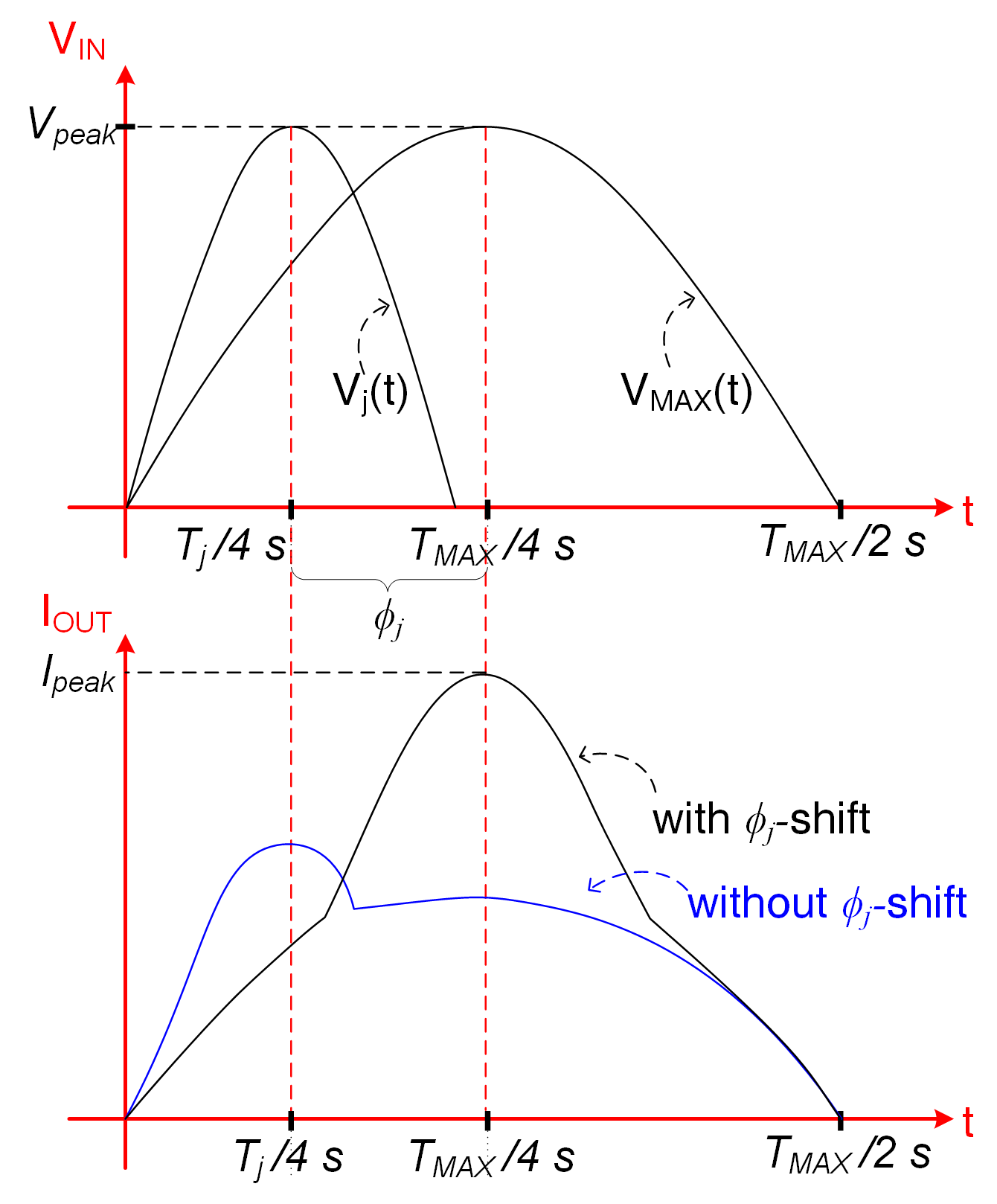
This results in a current waveform corresponding with a maximum amplitude , also shown in the bottom graph of Fig. 3. Putting everything together, with the knowledge that the input is a half-sine pulse, and expressing (2) in terms of frequency the equation for the input voltage of the row becomes:
| (3) |
where is the amplitude of , and is fixed for a full 2D convolution. As the voltage input is analogous to neuron input, from (3) corresponds to from (1).
We conclude this section by noting that phase-shift is not the only mechanism by which we can align pulses. It is also possible to introduce a time-delay at the output, for example by using an RC circuit. As we are already varying input frequency, we maintain consistency by modulating the phase instead of the output.
V Experimental Results
V-A Weight-to-Conductance
We experimentally demonstrate 2D convolution for image filtering in order to verify that our frequency-dependent scheme behaves correctly. We program weights in a single row of our crossbar to implement a convolutional Gaussian blur smoothing filter:
Here we map a kernel into input frequency in Hz, into memristor conductance in mS. As per Table I:
-
•
a weight of corresponds to ;
-
•
;
-
•
.222It is also possible to use , and in fact will typically require lower which provides an energy saving at the cost of longer inference cycles.
V-B Image Processing
The 2D convolution is performed using a 99 crossbar array and a 128128 8-bit unsigned representation of a photograph of Shibuya Crossing in Tokyo from Fig. 4(a) as input with GeSeSn-W memristors purchased from Knowm. The input image was pre-processed using artificial 8-bit RGB noise of uniform distribution with a mean of 127 and a peak of 255.
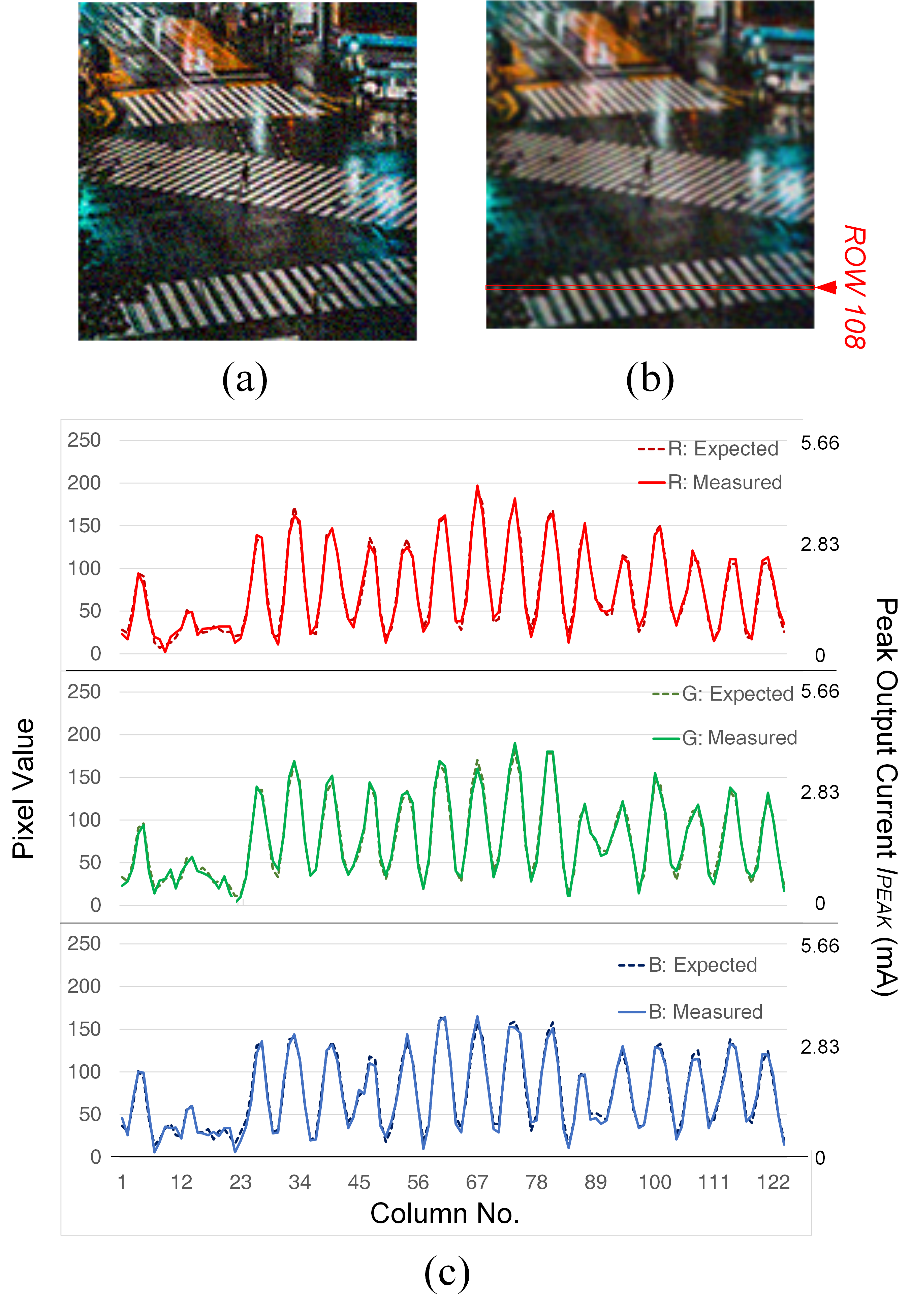
With the restriction on amplitude from Section IV of in mind, we choose for a luminance of 255, linearly decreasing (and then modulated to frequency variation) to for a luminance of 0. These voltages are applied to the rows of the crossbar 9 at a time, where each output pixel is generated by the dot product of a 9-dimensional conductance vector mapped from a 33 convolution matrix. The input image is convolved with a stride of one without zero-padding, so the dimension of the filtered image becomes 126126. We achieved this by performing 15,876 convolutions across each of the three RGB color channels. The peak current output of each color channel is displayed in Fig. 4(c), sampled across row 108 of the photograph. The peaks and troughs in the plot correspond to the alternation between dark and light patches across the pedestrian crossing. There is good agreement between the expected values calculated by Kirchhoff’s Current Law and the measured values, with the small fluctuations present due to line losses and the stochastic nature of memristors.
Physical multiplication of a 9-dimensional vector is accomplished by a single current read process on the column wires using a Micromanipulator tungsten probe tip, with a readout time of 500 ns. This is significantly slower than the readout time in [15] which is 10 ns, though this is a limitation of the device and not the frequency-dependent method itself. In terms of the method, one limitation is that we are unable to process different filters in parallel on the same crossbar, whereas the multi-level memristor in [15] was shown to process 10 separate convolutional filters simultaneously. This is because the weight is now a function of not only memristor conductance, but also of input frequency. Therefore, filters cannot be distributed across different weights. This is a reasonable drawback as we are able to achieve identical processes to multi-level memristors using binarized devices. Such a limitation can always be circumvented by introducing select transistors.
VI Discussion
This method is shown to work successfully for integrating 8-bit operations down to a single column, thus significantly reducing area for a single convolution linearly to 12.5% of the original size of a crossbar. This comparison does not factor the area overhead from the driving circuitry due to lack of information from prior literature, and because our input pulses and look-up table were implemented off-chip using a FPGA. On-chip implementation of input modulation is a non-trivial task, where the look-up table requires a multiplexer with select lines driven by hard-wired address signals.
In the experimental study from the previous section, we used three weight values which were programmed using the state. Once the operation started, there was no further need to re-write to the memristors – we only needed a single current read process on the column wire for each convolution. Approximate average power consumption per MAC operation can be calculated using the following equation:
| (4) |
where is the amplitude of the input. In comparison with conventional MAC crossbars such as that presented in [3], assuming identical conductances, this method exhibits an average power saving of factor where is the number of bits.333This calculation assumes ideal conditions without line resistance losses. These losses become important as the crossbar is scaled, though is negligible in our case of a 99 crossbar and additionally explains why our expected values agree well with our measured values. The factor comes from the term in AC power dissipation. Sneak paths and coupling effects do not impact results as our experiments are performed with discrete components, but should be considered when scaled down to an integrated circuit [16, 17] Quantitatively, for a single 2D Gaussian convolutional filter using 9 memristors along a single column, and assuming a worst case scenario where all input voltages have a maximum input peak of , the average power for a single MAC operation can be calculated using (4) to be 1.1mW. As a rough comparison, the process in [15] consumes 13.7mW for an image compression task although this is on a much larger 25-dimension voltage vector (i.e., 55 kernel). Regardless, it is evident this method is competitive with current state-of-the-art processes, whilst using devices that operate on much larger conductances. Therefore, there is good potential for further power savings if crossbars that operate with micro-scale conductances implement this frequency-dependent strategy.
VII Conclusion
This paper has presented a frequency-based mechanism for using binarized-conductance switching to generate analog weights, which is shown to reduce power when compared to column-distribution methods (as partially characterized by (4)), and to also reduce area by a factor equivalent to the number of bits used in image representation. This is performed without the need for multi-level memristors so can be implemented using phase-change memory switching or metal-oxide resistive switches, and is immaterial to the physical composition of the devices.
Importantly, we use a generalizable method that can implement different look-up tables by using different devices. While binarized NNs are known to perform well for most simple classification tasks, there is ultimately some compromise with accuracy that we are able to avoid using our anolog approach [18].
We achieve a highly efficient method for signal and image processing using convolution, and improvements in MAC operations in DNNs and CNNs. Future work includes testing this scheme on different devices to calculate read stability across various devices, and developing a way to pipeline frequency-dependency across columns to decrease latency.
Acknowledgements
This work was supported by the Australian Department of Foreign Affairs and Trade, Australia-Korea Foundation under Grant AKF00640, the Commonwealth Government of Australia through the Australian Government Research Training Program Scholarship, and iDataMap Corporation.
References
- [1] L. O. Chua and S. M. Kang, “Memristive devices and systems”, Proc. of the IEEE, vol. 64, no. 2, pp. 209–223, February 1976.
- [2] I. Hubara, M. Courbariaux, D. Soudy, R. El-Yaniv and Y. Bengio, “Binarized neural networks”, 30th Conf. on Neural Information Processing Syst. (NIPS 2016), Barcelona, Spain, pp. 4107–4115, December 2016.
- [3] A. Shafiee, A. Nag, N. Muralimanohar, R. Balasubramonian, J. P. Strachan, M. Hu, R. S. Williams and V. Srikumar, “ISAAC: A Convolutional neural network accelerator with in-situ analog arithmetic in crossbars”, 2016 ACM/IEEE 43rd Annual Int. Symp. on Computer Architecture (ISCA), Seoul, South Korea, June 2016.
- [4] J. K. Eshraghian, K. Cho, C. Zheng, M. Nam, H. H. C. Iu, W. Lei, K. Eshraghian, “Neuromorphic Vision Hybrid RRAM-CMOS Architecture”, IEEE Trans. on Very Large Scale Integration (VLSI) Syst., vol. 26, no. 12, pp. 2816–2829, December 2018.
- [5] Y. Kim, Y. Zhang and P. Li, “A digital neuromorphic VLSI architecture with memristor crossbar synaptic array for machine learning,” 2012 IEEE International SOC Conference (SOCC), pp. 328–333, September 2012.
- [6] X. Liu, M. Mao, B. Liu, H. Li, Y. Chen, B. Li, Y. Wang, H. Jiang, M. Barnell, Q. Wu and J. Yang, “RENO: A high-efficient reconfigurable neuromorphic computing accelerator design,” 2015 52nd ACM/EDAC/IEEE Design Automation Conference (DAC), San Francisco, CA, USA, June 2015.
- [7] J. K. Eshraghian, K. R. Cho, H.H.C. Iu, T. Fernando, N. Iannella, S. M. Kang and K. Eshraghian, “Maximization of Crossbar Array Memory Using Fundamental Memristor Theory,” IEEE Trans. Circuits and Syst. II: Exp. Briefs, vol. 64, no. 12, pp. 1402–1406, December 2017.
- [8] M. Prezioso, F. Merrikh-Bayat, B. Hoskins, G. Adam, K. K. Likharev and D. B. Strukov, “Training and Operation of an Integrated Neuromorphic Network based on Metal-Oxide Memristors”, Nature, vol. 521, pp. 61–64, May 2015.
- [9] T. M. Taha, R. Hasan, C. Yakopcic and M. R. McLean, “Exploring the design space of specialized multicore neural processors”, The 2013 Int. Joint Conf. on Neural Networks (IJCNN), Dallas, TX, USA, August 2013.
- [10] L. Song, X. Qian, H. Li and Y. Chen, “PipeLayer: A pipelined ReRAM-based accelerator for Deep Learning”, 2017 IEEE Int. Symp. on High Performance Computer Architecture (HPCA), Austin, TX, USA, February 2017.
- [11] J. Lee, J. K. Eshraghian, M. Jeong, F. Shan, H. H. C. Iu and K. Cho, “Nano-Programmable logics based on double-layer anti-facing memristors”, J. Nanoscience and Nanotechnology, vol. 19, no. 3, pp. 1295–1300, March 2019.
- [12] K. Cho, S. Baek, S. W. Cho, J. H. Kim, Y. S. Goo, J. K. Eshraghian, N. Iannella and K. Eshraghian, “Signal flow platform for mapping and simulation of vertebrate retina for sensor systems”, IEEE Sensors J., vol. 16, no. 15, pp. 5856–5866, August 2016.
- [13] J. K. Eshraghian, S. Baek, J. H. Kim, N. Iannella, K. Cho, Y. S. Goo, H. H. C. Iu, S. M. Kang and K. Eshraghian, “Formulation and implementation of nonlinear integral equations to model neural dynamics within the vertebrate retina”, Int. J. of Neural Syst., vol. 28, no. 7, p. e1850004, April 2018.
- [14] M. A. Nugent and T. W. Molter, “AHaH computing – from metastable switches to attractors to machine learning”, PLOS One, vol. 9, no. 2, p. e85175, February 2014.
- [15] C. Li, M. Hu, Y. Li, H. Jiang, N. Ge, E. Montgomery, J. Zhang, W. Song, N. Dávila, C.E. Graves and Z. Li, “Analogue signal and image processing with large memristor crossbars”, Nat. Electronics, vol. 1, pp. 52–59, January 2018.
- [16] J. K. Eshraghian, H. H. C. Iu, T. Fernando, D. Yu, Z. Li, “Modelling and characterization of dynamic behavior of coupled memristor circuits”, 2016 IEEE Int. Symp. on Circuits and Syst. (ISCAS), Montreal, Canada, May 2016, pp. 690–693.
- [17] C. Zheng, H. H. C. Iu, T. Fernando, D. Yu, H. Guo, J. K. Eshraghian, “Analysis and generation of chaos using compositely connected coupled memristors”, vol. 28, no. 6, Chaos: An Interdisciplinary J. of Nonlinear Science, p. e063115, June 2018.
- [18] R. Naous, M. Al-Shedivat, E. Neftci, G. Cauwenbergs and K. N. Salama, “Memristor-based neural network: synaptic versus neuronal stochasticity”, AIP Advances, vol. 6, p. e111304, November 2016.