Meron Spin Textures in Momentum Space
Abstract
We reveal the meron and antimeron spin textures in momentum space in a photonic crystal slab. These spin textures in momentum space have not been previously noted either in electronic or photonic systems. Breaking the inversion symmetry of a honeycomb photonic crystal gaps out the Dirac cones at the corners of Brillouin zone. The spin textures of photonic bands near the gaps exhibit a meron or antimeron. Unlike the electronic systems, the spin texture of the photonic modes manifests directly in the polarization of the leakage radiation, as the Dirac points can be above the light line. The spin texture provides a direct approach to visualize the local Berry curvature. Our work highlights the significant opportunities of using photonic structures for the exploration of topological spin textures, with potential applications towards topologically robust ways to manipulate polarizations and other modal characteristics of light.
Spin textures, the spin configuration in either real or momentum space, are of great interest in several subfields of physics. Skyrmion-related objects, including skyrmions, anti-skyrmions, merons, and anti-merons are topologically nontrivial spin textures. These textures have been extensively studied in various atomic and electronic systems such as Quantum Hall 2D electron gas, Bose-Einstein condensates, nematic liquid crystals and chiral magnets [1, 2, 3, 4, 5, 6, 7]. Antiskymions were discovered in tetragonal Heusler materials [8], while merons and antimerons in real space were discovered in chiral magnet thin film [9].
Since photons are massless spin-1 particles, skyrmion-related objects can also emerge as spin textures of photons [10, 11]. Real space skyrmions have been observed recently in surface plasmon polariton systems [11]. But there has not been any report of anti-skyrmions, merons and antimerons in optics. In this letter, using the honeycomb photonic crystal slab structure as shown in Fig. 1(a), we report meron and antimeron in momentum space. The existence of such objects has not been previously noted either in electronic or photonic systems. The observation of such spin textures may point to topologically robust ways to manipulate polarizations of light.
Skyrmion-related objects correspond to topologically nontrivial configurations of a three-component unit vector field distributed over a disk in a two-dimensional space with coordinates [12, 13]. They are all characterized by the topological skyrmion number
| (1) |
The unit vector fields form a -sphere . For skyrmions and antiskyrmions, one considers configurations where at the center of the disk, and at its edge. (This is referred to as the “core-up” configuration.) Since the fields are the same at the edge, one can compactify the edge to a single point to form a sphere. These field configurations thus correspond to maps of , which are characterized by the second homotopy group of the sphere , with an integer topological number characterizing topologically distinct ways that the unit vectors wrap around the sphere. and for skyrmions and antiskyrmions, respectively, for core-up configurations as discussed above. For core-down configurations, the signs are flipped, i.e. and for skyrmions and antiskyrmions, respectively.
For merons and antimerons, one considers configurations where at the disk center, at its edge, and over the whole disk. These field configurations correspond to maps of the disk to the upper hemisphere, with the disk edge imaged to the equator. With the following map:
| (2) |
which maps a hemisphere to a sphere with , all the points on the equator of the hemisphere are mapped to the south pole of the sphere. Applying this map to the meron or anti-meron configuration results in a field configuration with on the edge of the disk. One can then repeat the same compactification process as the skyrmion case, and obtain an integer as the topological number for . Since the continuous map from the field to the field doubles the solid angle subtended, we have . Therefore, merons and antimerons are characterized by half-integer skyrmion numbers: and for core-up merons and antimerons, respectively; the signs are flipped for core-down merons and antimerons 111This convention of meron and antimeron is the same as most of the papers on the subject except Ref. [9], where a different convention is used..
In addition to the topological number , skyrmion-related objects are further characterized by their polarity and vorticity . for and for at the center [15]. The vorticity indicates the rotation direction of the in-plane components of . Along a counterclockwise loop around the center, for a given , the in-plane components rotate an angle of counterclockwise. Skyrmions and merons have ; antiskyrmions and antimerons have .
Skyrmion-related objects can also emerge as spin textures of photons which are massless spin- particles [10, 11]. Consider a polarization state as characterized by a density matrix , with the basis being the right and left circularly polarized states and . The Stokes parameters are defined as where ; are the Pauli spin matrices [16, 17]. For a pure polarization state , , thus its polarization is completely characterized by a three-component unit vector, also denoted as :
| (3) |
All ’s form a unit -sphere known as Poincaré sphere. The Poincaré sphere of massless spin- photon is identical to the Bloch sphere of spin- electron [18].
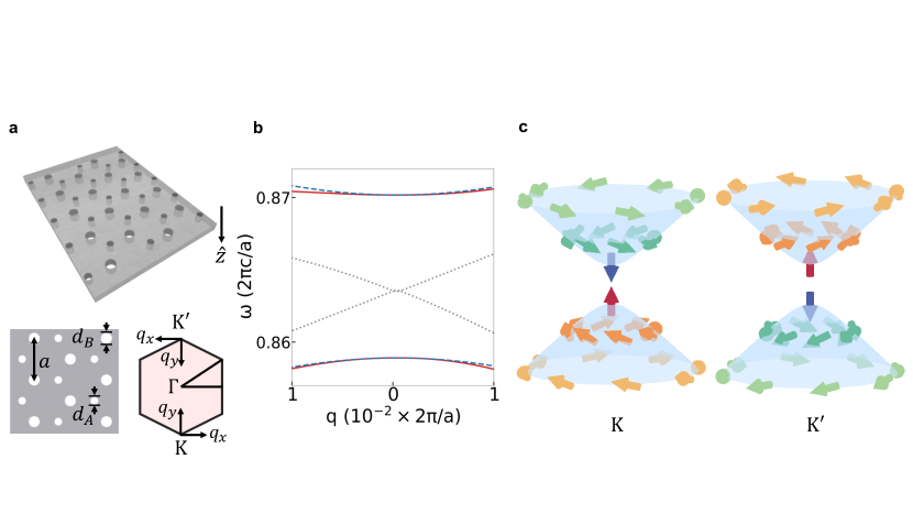
Here using photonic systems we show meron and anti-meron spin textures in momentum space. We consider a photonic crystal slab consisting of a honeycomb lattice of circular air holes, where the holes at the two inequivalent sublattice sites are of different sizes [Fig. 1(a)]. For concreteness, the dielectric constant of the slab is , which approximates the dielectric constant of SiN at visible wavelengths.
The photonic band structure of the system exhibits a Dirac cone at and when [black in Fig. 1(b)]. Breaking the inversion symmetry () gaps out the Dirac cone, resulting in two valleys at and [19, 20] [red in Fig. 1(b)]. The system thus exhibits valley-contrasting physics similar to that in several two dimensional semiconductors [21, 22].
Breaking inversion symmetry induces meron pseudo-spin texture aound and . In the vicinity of and , the system is described by an effective Hamiltonian as obtained using the method [23, 24, 25]:
| (4) |
where the plus (minus) sign corresponds to (). In this paper, measures the difference of the wavevector from or , with axis pointing towards , and , where is the unit vector perpendicular to the slab (Fig. 1a). are the Pauli matrices of the pseudo-spin. defines the pseudo-spin texture with being an eigenstate at . The basis of is chosen such that correspond to the even/odd states with respect to the axis, and correspond to the clockwise/anticlockwise-rotating states with respect to [25, 20]. Below, we refer to the states and as the “up” and “down” pseudo-spin states, respectively. is the group velocity. The term with breaks inversion symmetry and induces a bandgap of size .
Figure 1(b) plots the eigenvalues of the Hamiltonian in Eq. (4) (blue dashed lines) with fitting parameters , where is the speed of light in vacuum. agrees well with the numerically determined photonic bands near and for the physical structure.
Figure 1(c) depicts the pseudo-spin textures as obtained using Eq. (4). At point (), the pseudo-spin is up for the lower band and down for the upper band. Far away from point (), the pseudo-spins lie in the equatorial plane with vorticity . The pseudo-spin textures around are thus identified as core-up (core-down) meron for the lower (upper) band. Moreover, the in-plane pseudo-spin components are locked at right angles with wavevector . around and are related: suppose a state in the lower band at around has a pseudo-spin , the corresponding state in the lower band at the same around has a pseudo-spin . The same mapping applies for the upper band. Therefore, the pseudo-spin textures around are core-down (core-up) meron for the lower (upper) band. The meron pseudo-spin textures manifest the localized Berry curvature and the Berry phase around and [21].
We proceed to show that the meron pseudo-spin textures, and hence the local Berry curvature of the photonic bands, can be directly observed as the meron/antimeron spin texture of radiated photons. In our system, the valleys are above the light line since . Consequently, unlike electronic systems, here the excited photonic modes will radiate out, and the leakage radiation carries information of the eigenmodes. Specifically, with respect to Fig. 1(a), suppose light is incident from the side with the propagation direction indicated by a unit vector . We define the S and P polarizations as having their electric field along the directions and , respectively, and the right/left circular polarization (RCP/LCP) as having their electric fields along the directions and , respectively, where we adopt the convention of . The conventions of the Poincaré sphere are chosen so that correspond to RCP/LCP, and correspond to P/S polarizations. Now we consider the map between pseudo-spin of the eigenmode and spin of the radiated photons. The radiation process can be described by a linear map , where are the internal states in the slab and are the corresponding leakage radiation. can be expanded on the eigenbasis of , which correpsonds to even/odd states with respect to the axis. The even/odd states radiate into P/S polarized states only, i.e. , , where the relative phase between and are fixed such that at the transmission side; consequently, at the reflection side. This map then induces a map between the pseudo-spin of photons in the slab and the spin of radiated photons as . For transmission, ; for reflection, . As a result, the meron pseudo-spin textures around and can be directly observed as meron spin textures at the transmission side and antimeron spin textures at the reflection side.
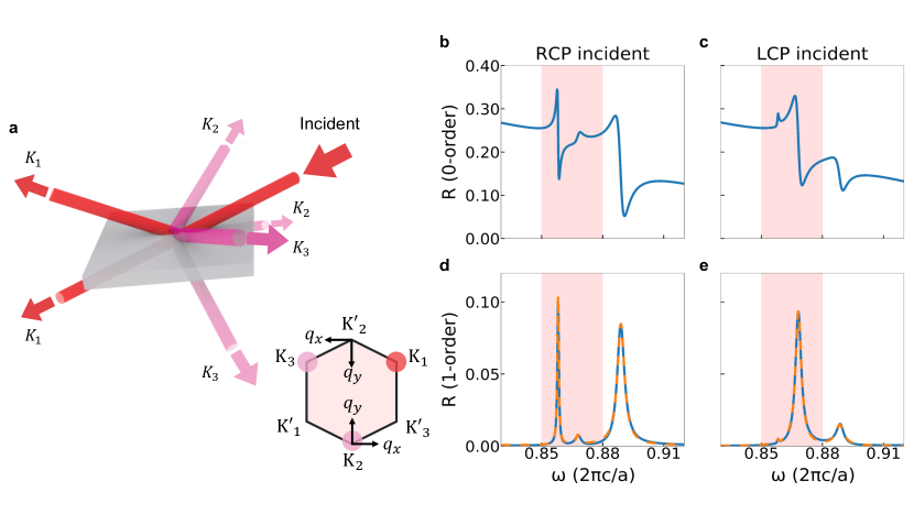
In a typical optical experiment, the modes are excited by an externally incident beam. In order to use the measured polarization properties to infer the pseudo-spin properties of the photonic modes, it is important that the light being measured contains only the radiated photons from the modes, without any interference from direct reflection/transmission of the incident bream. Therefore, we propose the setup in Fig. 2(a), where we measure the polarization of light in high-order diffraction channels. Light with a specific frequency and polarization is incident on the sample at a specific angle to excite a desired photonic mode around one Brillouin zone corner (). Due to the periodicity of the lattice, the excited mode radiates out to both \nth0-order () and \nth1-order ( and ) channels on both the transmission and reflection sides. Figs. 2(b-e) show the calculated \nth0-order/\nth1-order reflection spectra for the RCP/LCP incident light with fixed parallel wavevector . The \nth0-order spectra in Figs. 2(b) and 2(c) exhibit Fano resonance lineshapes, superimposed upon a smoothly varying background corresponding to direct reflection [26]. This indicates strong interference between the directly reflected incident light and leakage radiation from the modes in the slab. In contrast, the \nth1-order spectra in Figs. 2(d) and 2(e) exhibit resonances with Lorentzian lineshapes with negligible background, indicating a negligible contribution from the direct reflection of the incident light. The wave amplitudes in these diffraction orders therefore arise entirely from the leakage radiation from the photonic mode in the slab. We emphasize that in this case, as long as the mode is excited, the polarization of the leakage radiation is independent of the polarization of the incident light. In general we can selectively excite either the upper or the lower band with the use of different frequencies. Near the point, where the difference in frequencies between the two bands is relatively small, we note that incident light with RCP (LCP) selectively excites the lower (upper) state [20] at point, as shown in Fig. 2(d) and 2(e). In this case therefore we can in addition use different polarizations of the incident light to selectively excite the upper and lower band.
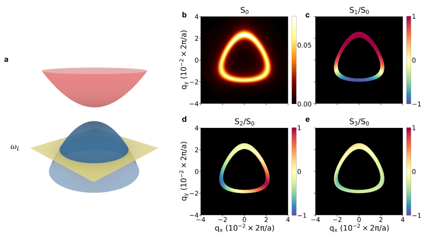
We now numerically study the polarization states of the photons in the \nth1-order diffraction channel. The directions, frequencies and polarization of the incident light are chosen so that we probe the lower valley near point. At each frequency, we scan the incident parallel wavevectors around , and calculate the four Stokes parameters from the electric fields of the \nth1-order reflected light around [Fig. 3(a)]. Figs. 3(b-e) plot the simulation results at the frequency . Figure 3(b) shows the intensity distribution of \nth1-order reflected light in momentum space, where the bright peaks match the isofrequency contour of the lower band. Figure 3(c-e) show normalized Stokes parameters , and , respectively. Since the Stoke parameters are not well defined for , we only show results for . The polarizations show significant variation in the direction along the isofrequency contour, but far less variation in the direction perpendicular to the contour. This is consistent with the fact that the spin texture of the leakage radiation manifests the pseudo-spin texture of the underlying photonic modes in this setup.
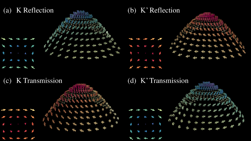
In Fig. 4, we plot the spin textures of the leakage radiation on the iso-frequency contours of the photonic band structure. Near the -valley, for the reflected light in the \nth1-order channel, the texture corresponds to a core-down antimeron with skymion number , polarity and vorticity [Fig. 4(a)]. At the point, the spin points down (), corresponding to LCP. Away from the -point the spin gradually rotates to the equatorial plane, corresponding to linearly-polarized light. Notice that the in-plane spin components on the circle around the -point have a winding number of . At the -valley, the spin texture of the reflected light corresponds to a core-up anti-meron with [Fig. 4(b)]. This texture has the same winding characteristics as the texture shown in Fig. 4(a), but with spin up at the core of . For the transmitted light in the \nth1-order channel, the texture corresponds to a core-up meron at with [Fig. 4(c)], and a core-down meron at with [Fig. 4(d)]. Notice the in-plane spin components have a winding number of . The relation of spin textures between the transmitted and reflected lights can be explained by the mirror symmetry of the modes in the slab, whereas the relation of the textures between the and valley can be explained by time-reversal symmetry and the adopted coordinate system. The observed spin texture of the leakage radiation corresponds well to the pseudo-spin texture of the photonic modes in the slab as described by Eq. (4). The analysis of the leakage radiation provides a direct visualization of the intriguing connection of spin, pseudo-spin, valley and band topology in the photonic valleytronic systems. In particular, our setup directly maps out the Berry curvature, which has only been probed indirectly by wave packet transport [27].
In conclusion, we reveal the intrinsic meron pseudo-spin texture in momentum space in a photonic crystal slab, which can be directly observed as meron and antimeron spin texture by polarimetric study of high-order diffracted light from the system. Such spin texture in momentum space has not been previously observed in either electronic or photonic systems. Our work indicates significant opportunities of using photonic structures to explore topologically non-trivial spin textures. Our result may also be important for arbitrary polarization generation [28, 29, 30]. For example, in this system, by changing the angle of incidence near the point by a small amount, a wide variety of different polarizations can be generated.
This work is supported by the National Science Foundation (CBET-1641069).
References
- Al Khawaja and Stoof [2001] U. Al Khawaja and H. Stoof, Skyrmions in a ferromagnetic Bose-Einstein condensate, Nature 411, 918 (2001).
- Rößler et al. [2006] U. K. Rößler, A. N. Bogdanov, and C. Pfleiderer, Spontaneous skyrmion ground states in magnetic metals, Nature 442, 797 (2006).
- Barrett et al. [1995] S. E. Barrett, G. Dabbagh, L. N. Pfeiffer, K. W. West, and R. Tycko, Optically pumped NMR evidence for finite-size Skyrmions in GaAs quantum wells near Landau level filling =1, Phys. Rev. Lett. 74, 5112 (1995).
- Muhlbauer et al. [2009] S. Muhlbauer, B. Binz, F. Jonietz, C. Pfleiderer, A. Rosch, A. Neubauer, R. Georgii, and P. Boni, Skyrmion Lattice in a Chiral Magnet, Science 323, 915 (2009).
- Yu et al. [2010] X. Z. Yu, Y. Onose, N. Kanazawa, J. H. Park, J. H. Han, Y. Matsui, N. Nagaosa, and Y. Tokura, Real-space observation of a two-dimensional skyrmion crystal, Nature 465, 901 (2010).
- Fukuda and Žumer [2011] J.-i. Fukuda and S. Žumer, Quasi-two-dimensional Skyrmion lattices in a chiral nematic liquid crystal, Nat. Commun. 2, 246 (2011).
- Nych et al. [2017] A. Nych, J.-i. Fukuda, U. Ognysta, S. Žumer, and I. Muševič, Spontaneous formation and dynamics of half-skyrmions in a chiral liquid-crystal film, Nat. Phys. 13, 1215 (2017).
- Nayak et al. [2017] A. K. Nayak, V. Kumar, T. Ma, P. Werner, E. Pippel, R. Sahoo, F. Damay, U. K. Rößler, C. Felser, and S. S. P. Parkin, Magnetic antiskyrmions above room temperature in tetragonal Heusler materials, Nature 548, 561 (2017).
- Yu et al. [2018] X. Z. Yu, W. Koshibae, Y. Tokunaga, K. Shibata, Y. Taguchi, N. Nagaosa, and Y. Tokura, Transformation between meron and skyrmion topological spin textures in a chiral magnet, Nature 564, 95 (2018).
- Van Mechelen and Jacob [2019] T. Van Mechelen and Z. Jacob, Photonic Dirac monopoles and skyrmions: spin-1 quantization, Opt. Mater. Express 9, 95 (2019).
- Tsesses et al. [2018] S. Tsesses, E. Ostrovsky, K. Cohen, B. Gjonaj, N. H. Lindner, and G. Bartal, Optical skyrmion lattice in evanescent electromagnetic fields, Science 361, 993 (2018).
- Fert et al. [2017] A. Fert, N. Reyren, and V. Cros, Magnetic skyrmions: advances in physics and potential applications, Nat. Rev. Mater. 2, 17031 (2017).
- Nagaosa and Tokura [2013] N. Nagaosa and Y. Tokura, Topological properties and dynamics of magnetic skyrmions, Nat. Nanotechnol. 8, 899 (2013).
- Note [1] This convention of meron and antimeron is the same as most of the papers on the subject except Ref. [9], where a different convention is used.
- Kovalev and Sandhoefner [2018] A. A. Kovalev and S. Sandhoefner, Skyrmions and Antiskyrmions in Quasi-Two-Dimensional Magnets, Front. Phys. 6, 1 (2018).
- Fano [1949] U. Fano, Remarks on the Classical and Quantum-Mechanical Treatment of Partial Polarization, J. Opt. Soc. Am. 39, 859 (1949).
- Falkoff and MacDonald [1951] D. L. Falkoff and J. E. MacDonald, On the Stokes Parameters for Polarized Radiation, J. Opt. Soc. Am. 41, 861 (1951).
- Penrose [2005] R. Penrose, The road to reality : a complete guide to the laws of the universe (Vintage, London, 2005).
- Dong et al. [2017] J.-W. Dong, X.-D. Chen, H. Zhu, Y. Wang, and X. Zhang, Valley photonic crystals for control of spin and topology, Nat. Mater. 16, 298 (2017).
- Chen et al. [2017a] X.-D. Chen, F.-l. Zhao, M. Chen, and J.-w. Dong, Valley-contrasting physics in all-dielectric photonic crystals: Orbital angular momentum and topological propagation, Phys. Rev. B 96, 020202 (2017a).
- Xiao et al. [2007] D. Xiao, W. Yao, and Q. Niu, Valley-Contrasting Physics in Graphene: Magnetic Moment and Topological Transport, Phys. Rev. Lett. 99, 236809 (2007).
- Cao et al. [2012] T. Cao, G. Wang, W. Han, H. Ye, C. Zhu, J. Shi, Q. Niu, P. Tan, E. Wang, B. Liu, and J. Feng, Valley-selective circular dichroism of monolayer molybdenum disulphide, Nat. Commun. 3, 887 (2012).
- Chen et al. [2017b] A. Chen, W. Liu, Y. Zhang, B. Wang, F. Guan, X. Liu, L. Shi, L. Lu, and J. Zi, Observing half and integer polarization vortices at band degeneracies, (2017b), arXiv:1712.09296 .
- Ma and Shvets [2016] T. Ma and G. Shvets, All-Si valley-Hall photonic topological insulator, New J. Phys. 18, 025012 (2016).
- Khanikaev et al. [2013] A. B. Khanikaev, S. Hossein Mousavi, W.-k. Tse, M. Kargarian, A. H. MacDonald, and G. Shvets, Photonic topological insulators, Nat. Mater. 12, 233 (2013).
- Fan and Joannopoulos [2002] S. Fan and J. D. Joannopoulos, Analysis of guided resonances in photonic crystal slabs, Phys. Rev. B 65, 235112 (2002).
- Wimmer et al. [2017] M. Wimmer, H. M. Price, I. Carusotto, and U. Peschel, Experimental measurement of the berry curvature from anomalous transport, Nature Physics 13, 545 (2017).
- Guo et al. [2019] Y. Guo, M. Xiao, Y. Zhou, and S. Fan, Arbitrary Polarization Conversion with a Photonic Crystal Slab, Adv. Opt. Mater. 1801453, 1801453 (2019).
- Zhang et al. [2018] Y. Zhang, A. Chen, W. Liu, C. W. Hsu, B. Wang, F. Guan, X. Liu, L. Shi, L. Lu, and J. Zi, Observation of Polarization Vortices in Momentum Space, Phys. Rev. Lett. 120, 186103 (2018).
- Doeleman et al. [2018] H. M. Doeleman, F. Monticone, W. den Hollander, A. Alù, and A. F. Koenderink, Experimental observation of a polarization vortex at an optical bound state in the continuum, Nat. Photonics 12, 397 (2018).