Fast two-qubit logic with holes in germanium
The promise of quantum computation with quantum dots has stimulated widespread research. Still, a platform that can combine excellent control with fast and high-fidelity operation is absent. Here, we show single and two-qubit operations based on holes in germanium. A high degree of control over the tunnel coupling and detuning is obtained by exploiting quantum wells with very low disorder and by working in a virtual gate space. Spin-orbit coupling obviates the need for microscopic elements and enables rapid qubit control with Rabi frequencies exceeding 100 MHz and a single-qubit fidelity of 99.3 %. We demonstrate fast two-qubit CX gates executed within 75 ns and minimize decoherence by operating at the charge symmetry point. Planar germanium thus matured within one year from a material that can host quantum dots to a platform enabling two-qubit logic, positioning itself as a unique material to scale up spin qubits for quantum information.
Gate-defined quantum dots were recognized early on as a promising platform for quantum information Loss and DiVincenzo (1998) and a plethora of materials stacks has been investigated as host material. Initial research mainly focused on the low disorder semiconductor gallium arsenide Koppens et al. (2006); Petta et al. (2005). Steady progress in the control and understanding of this system culminated in the initial demonstration and optimization of spin qubit operations Bluhm et al. (2011); Foletti et al. (2009) and the realization of rudimentary analog quantum simulations Hensgens et al. (2017). However, the omnipresent hyperfine interactions in group III-V materials seriously deteriorate the spin coherence, despite attempts to mitigate this by nuclear polarization Bluhm et al. (2010). Drastic improvements to the coherence times could be achieved by switching to the group IV semiconductor silicon, in particular when defining spin qubits in isotopically purified host crystal with vanishing concentrations of nonzero nuclear spin Veldhorst et al. (2014). This enabled single qubit rotations with fidelities beyond 99.9% Yoneda et al. (2017) and the execution of two-qubit logic gates with fidelities up to 98% Veldhorst et al. (2015); Zajac et al. (2018); Watson et al. (2018); Huang et al. (2018), underlining the potential of spin qubits for quantum computation. Nevertheless, quantum dots in silicon are often formed at unintended locations and control over the tunnel coupling determining the strength of two-qubit interactions is limited. Moreover, the absence of a sizable spin-orbit coupling for electrons requires the inclusion of microscopic components such as on-chip striplines or nanomagnets close to each qubit, which seriously complicates the design of large and dense 2D-structures. This, combined with the limited control over the location and coupling of the dots, remains an outstanding challenge for the scalability of these systems and a platform that can overcome these limitations would be highly desirable.
Hole states in semiconductors typically exhibit strong spin-orbit coupling, which has enabled the demonstration of fast single qubit rotations Nadj-Perge et al. (2010); Watzinger et al. (2018) and additionally, unlike electrons, holes do not suffer from nearby valley states. In silicon, unfavorable band alignment prevents strain engineering of low disorder quantum wells for holes, restricting experiments to metal-oxide-semiconductor (MOS) structures Li et al. (2015); Liles et al. (2018). Research on germanium mostly focused on self-assembled nanowires Hu et al. (2012); Brauns et al. (2016); Higginbotham et al. (2014) and demonstrated single-shot spin readout Vukušić et al. (2018) and coherent spin control Watzinger et al. (2018). However, strained germanium quantum wells were recently shown to support the formation of gate-controlled planar hole quantum dots Hendrickx et al. (2018); Hardy et al. (2019). Now, the crucial challenge is the demonstration of coherent control in this platform and the implementation of qubit-qubit gates for quantum information with holes.
Here, we make this step and demonstrate single and two qubit logic with holes in planar germanium. Fabrication is based on silicon substrates and standard manufacturing materials. We grow strained germanium quantum wells, measured to have high hole mobilities 500.000 cm2/Vs and a low effective hole mass = 0.09 Hendrickx et al. (2018); Sammak et al. (2019), and predicted to reach = 0.05 at zero density Morrison et al. (2014); Terrazos et al. (2018). This allows us to define quantum dots of comparatively large size and we find excellent control over the exchange interaction between the two dots. We operate in a multi-hole mode, significantly reducing challenges in tuning and characterization, and thereby advantageous for scaling. We exploit the spin-orbit interaction for qubit driving and perform single qubit rotations at frequencies exceeding 100 MHz. This advantage of fast driving becomes further apparent in coherently accessing the Hilbert space of a two-qubit system. For example, in silicon the execution of a CNOT gate implemented with an on-chip stripline has been shown using microsecond long pulses Veldhorst et al. (2015); Huang et al. (2018) and this timescale is typically reduced to 0.2-0.5 microseconds by incorporating nanomagnets Watson et al. (2018); Zajac et al. (2018). Here, we demonstrate that the spin-orbit coupling of holes in germanium together with the sizable exchange interaction enables a CNOT within = 75 ns.
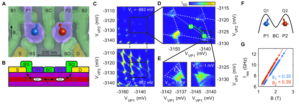
A scanning electron microscope (SEM) image of the germanium two-qubit device is shown in Fig. 1A. In order to accumulate holes and define two quantum dots, the two circular plunger gates are set to negative potential ( V). The tunnel coupling between the dots and the tunnel couplings to the source and drain reservoirs (, ) are controlled by the barrier gates BC, BS and BD, respectively. Working in a virtual gate voltage space (V, V, V, V, and V, respectively), we can independently tune these properties (see video mode operation in supplementary materials). We measure the transport current through the double dot system (Fig. 1C and 1D) and for certain hole occupations we observe a suppression of the transport current for a positive bias voltage mV, caused by Pauli-spin blockade (PSB) Ono et al. (2002), see Fig. 1E. We make use of the blockade as an effective method for spin-to-charge conversion Petta et al. (2005), as well as to initialize our two qubit system in the blocked ground state.
Taking advantage of the strong spin-orbit coupling Terrazos et al. (2018); Watzinger et al. (2018), we are able to implement a fast manipulation of the qubit states by electric dipole spin resonance (EDSR). We tune the device to a read-out point within the PSB-region (indicated by the label R in Fig. 1D) and apply an electric microwave excitation to gate P1. When the frequency of the microwave excitation matches the spin resonance frequency of either qubit, the PSB is lifted and an increase in the transport current can be observed. We extract the resonance frequency of each qubit as a function of external magnetic field strength and observe two distinct qubit resonance lines with -factors and (Fig. 1G). The difference in g-factors between the two dots is likely caused by slightly different hole fillings and thus quantum dot orbitals. Due to the influence of spin-orbit coupling, a strong orbital dependence of the effective -factor is typically expected in hole quantum dots Liles et al. (2018); Nenashev et al. (2003). Furthermore the effective -factor can be tuned electrically as a direct result of the SOC Maier et al. (2013) (see e.g. Fig. 4C and 4D), thereby guaranteeing independent control of the different qubits.
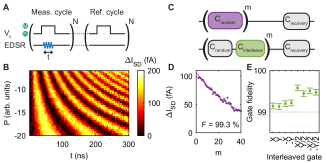
To allow for coherent control of the isolated spin states, a two-level voltage pulse on gates P1 and P2 is used to detune the dot potentials and prevent tunneling to and from the dots during the manipulation phase (label M in Fig. 1D). We measure the averaged transport current over repeated pulse cycles and subtract a reference measurement to mitigate slow drifts in the transport current (cf. supplementary materials), as is indicated in Fig. 2A. The number of repetitions of each cycle is chosen to result in a lock-in frequency of Hz. During the readout (label R in Fig. 1E), no differential current is observed when the qubits are in their ground state, while a signal of typically pA is measured for all other configurations and a total cycle length of ns. This is in good agreement with a bias current pA, as expected for the random loading of a hole spin. After readout, the system is left in the blocking state, serving as the initialization of our qubits.
We now operate the device in the single-qubit transport mode in an external field of T and use the second qubit as a readout ancilla. Coherent control over the qubit is demonstrated in a Rabi experiment, where the spin state of Q1 is measured as a function of microwave pulse length and power , as shown in Fig. 2B. By increasing the power of the microwave pulse, we can reach Rabi frequencies of over a MHz, at an elevated T (as shown in the supplementary materials).
To evaluate the performance of our device, we implement randomized benchmarking of the single qubit Clifford group Knill et al. (2008) (Fig. 2C). The measured decay curve of the qubits state as a function of sequence length is shown in Fig. 2D, from which we can extract a single qubit control fidelity of . Each data point is averaged over approximately 100000 repetitions of 1500 randomly drawn gate sequences. For each of these sequences, two recovery gates C are chosen such that the qubit is projected to the and state, respectively, realizing alternating cycles for lock-in detection. In Fig. 2E we show the gate fidelities for the different and gates as obtained by interleaved randomized benchmarking, where each randomly drawn gate is followed by the interleaved gate (cf. Fig. 2C). All individual gate fidelities are , with the infidelity for gates being approximately twice as low as for the gates, on account of the difference in pulse length.
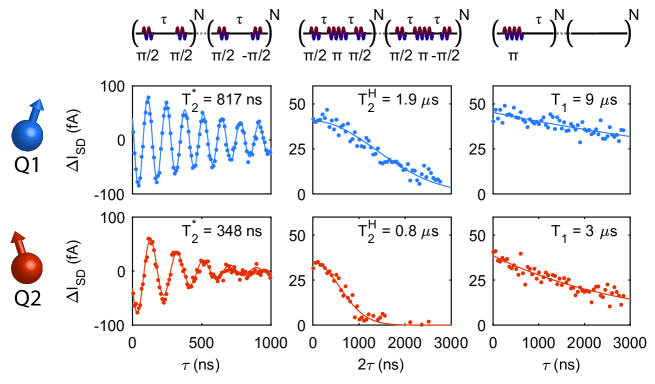
We further characterize the individual qubits by measuring the coherence and relaxation times. We perform a Ramsey experiment, in which two pulses are separated by time , during which the qubit will evolve as a result of the implemented detuning. We fit the decay of the observed oscillations to and find a spin coherence time of ns and ns and decay coefficients of and , for Q1 and Q2 respectively. These coherence times are a few times larger than reported for germanium hut wires Watzinger et al. (2018). We note that due to the nature of the transport measurements, we cannot turn the coupling between the qubits fully off and thus a residual coupling of MHz remains for these measurements, potentially limiting the single qubit performance.
The spin coherence can be extended by performing a Hahn echoing sequence, consisting of , and pulses separated by waiting times . Fitting the observed decay as a function of the total waiting time to a power law , we find extended coherence times of s and s and decay coefficients of and , for Q1 and Q2 respectively. Arsenic dopents in natural germanium attain values of s and can reach long quantum coherence with in isotopically purified samples. The difference in quantum coherence may have different origins, for example due to a difference in hyperfine interaction, in which case a dramatic improvement may be expected for isotopically purified germanium quantum dots Itoh et al. (1993); Itoh and Watanabe (2014).
Finally, we perform measurements of the spin relaxation times of the qubits by applying a pulse and waiting for time before performing readout. We observe spin relaxation times of s and s. Furthermore, we find that these relaxation times increase exponentially when lowering the tunnel coupling between each qubit and its respective reservoir (data in supplementary materials) and longer relaxation times have been reported for germanium nanowires Hu et al. (2012); Vukušić et al. (2018), giving good prospect for significantly increasing the relaxation time by closing the reservoir barrier during operation.
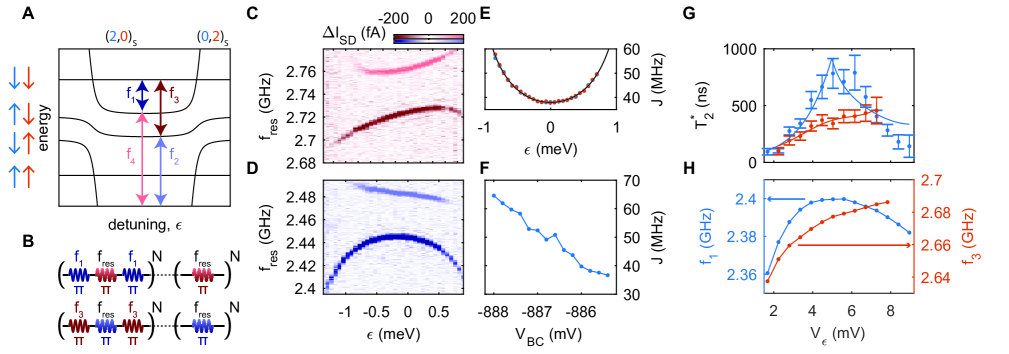
When the manipulation of both qubits is combined, the coupling of the two qubits (exchange interaction ) becomes apparent. As is illustrated in Fig. 4A, the resonance frequency of each of the qubits is shifted when the respective other qubit is prepared in its state. The strength of this interaction depends on the inter-dot tunnel coupling as well as the detuning of the dot potentials. By changing the depth of voltage pulse to point M (dashed line in Fig. 1E), we can map as a function of . This is shown in Fig. 4C and 4D, where the subtraction of two pulse sequences in the measurement (see Fig. 4B) results in a positive signal for the unprepared qubit resonances and a negative signal for the prepared states (cf. supplementary materials). As shown in Fig. 4E, the exchange coupling that is reflected in the frequency difference between the initial and prepared resonance positions, is very well described by a simple description using Russ et al. (2018); Loss and DiVincenzo (1998). Here, is the charging energy of the quantum dots, is the lever arm of P1 and P2, the interdot tunnel coupling is GHz. In addition, the strength of can be tuned using the central barrier BC (Fig. 4F). Here, we use a virtual gate voltage , where is set while compensating its influence on the dot potentials by appropriate corrections to and Hensgens et al. (2017); van Diepen et al. (2018). As a result of this full control over the coupling, we are able to operate the qubits at a mostly charge-insensitive point of symmetric detuning while choosing an exchange coupling strength large enough for rapid two qubit controlled rotations.
The advantage of this reduced sensitivity to detuning noise is demonstrated in Fig. 4G, where the dephasing time of both qubits is measured as a function of . Here, directly reflects the slope of the frequency dependence of for Q1 and Q2, with the longest average phase coherence reached in the flat region mV.
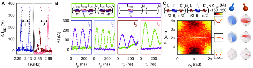
The direct control over the tunnel coupling enables us to set the exchange interaction to a sizable strength of MHz at the symmetry point, as demonstrated in Fig. 5A. We exploit this regime to obtain fast selective driving and operate in an exchange always-on mode. Full control is obtained by applying microwave pulses at the four resonant frequencies, while further gate pulses controlling are not needed. A pulse at a single resonance frequency will result in a conditional rotation of the target qubit, as we show in Fig. 5B. The slight off-resonant driving that can be observed on is mitigated by choosing the driving speed such that . A fast CX-operation is thus achieved within = 55 ns and = 75 ns, with Q1 and Q2 as the target qubits respectively.
As a result of the pulsing, we observe a minor shift in the resonance frequency of both qubits. This was observed before in Si/SiGe quantum dots Takeda et al. (2018), and we speculate this to be caused by a rectification of the AC microwave signal, leading to a slight change in the exchange interaction between the dots. We compensate the temporary change in resonance frequency by applying phase corrections to all following pulses (see supplementary materials). In Fig. 5C we show the effect of a controlled rotation on the control qubit with applied phase corrections. We first apply a pulse to Q2, followed by a conditional rotation of Q1. Finally, we apply a virtual gate by directly switching the phase on the final conditional pulse on Q2 (). We observe larger phase rotations on Q1 after 0 and rotations on Q2 as compared to a rotation on Q2. This periodicity is in agreement with fermionic statistics and suggests an echoing pulse correcting residual environmental coupling (see supplementary material). The full phase shift on Q2 for a conditional rotation on Q1, as a result of the phase that is accumulated by the control qubit, demonstrates the application of a coherent CX gate.
The demonstration of a universal gate set with all electrical control and without the need of any microscopic structures provide great prospects to scale up spin qubits using holes in strained germanium. These quantum dots are furthermore contacted by superconductors Hendrickx et al. (2018, 2019); Vigneau et al. (2019) that may be shaped into microwave resonators for spin-photon coupling, providing opportunities for a platform that can combine semiconducting, superconducting, and topological systems for hybrid technology with fast and coherent control over individual hole spins. Moreover, the demonstrated quantum coherence and level of control make planar germanium a natural candidate to engineer artificial Hamiltonians for quantum simulation going beyond classically tractable experiments.
Acknowledgements.
We thank L.M.K. Vandersypen, S. Dobrovitski and J. Helsen for valuable discussions. We acknowledge support through a FOM Projectruimte of the Foundation for Fundamental Research on Matter (FOM), associated with the Netherlands Organisation for Scientific Research (NWO).References
- Loss and DiVincenzo (1998) D. Loss and D. P. DiVincenzo, Phys. Rev. A 57, 120 (1998).
- Koppens et al. (2006) F. H. L. Koppens, C. Buizert, K. J. Tielrooij, I. T. Vink, K. C. Nowack, T. Meunier, L. P. Kouwenhoven, and L. M. K. Vandersypen, Nature 442, 766 (2006).
- Petta et al. (2005) J. R. Petta, A. C. Johnson, J. M. Taylor, E. A. Laird, A. Yacoby, M. D. Lukin, C. M. Marcus, M. P. Hanson, and A. C. Gossard, Science 309, 2180 (2005).
- Bluhm et al. (2011) H. Bluhm, S. Foletti, I. Neder, M. Rudner, D. Mahalu, V. Umansky, and A. Yacoby, Nature Physics 7, 109 (2011).
- Foletti et al. (2009) S. Foletti, H. Bluhm, D. Mahalu, V. Umansky, and A. Yacoby, Nature Physics 5, 903 (2009).
- Hensgens et al. (2017) T. Hensgens, T. Fujita, L. Janssen, X. Li, C. J. Van Diepen, C. Reichl, W. Wegscheider, S. Das Sarma, and L. M. K. Vandersypen, Nature 548, 70 (2017).
- Bluhm et al. (2010) H. Bluhm, S. Foletti, D. Mahalu, V. Umansky, and A. Yacoby, Phys. Rev. Lett. 105 (2010), 10.1103/PhysRevLett.105.216803.
- Veldhorst et al. (2014) M. Veldhorst, J. C. C. Hwang, C. H. Yang, A. W. Leenstra, B. d. Ronde, J. P. Dehollain, J. T. Muhonen, F. E. Hudson, K. M. Itoh, A. Morello, and A. S. Dzurak, Nat. Nanotech. 9, 981 (2014).
- Yoneda et al. (2017) J. Yoneda, K. Takeda, T. Otsuka, T. Nakajima, M. R. Delbecq, G. Allison, T. Honda, T. Kodera, S. Oda, Y. Hoshi, N. Usami, K. M. Itoh, and S. Tarucha, Nat. Nanotech. , 102 (2017).
- Veldhorst et al. (2015) M. Veldhorst, C. H. Yang, J. C. C. Hwang, W. Huang, J. P. Dehollain, J. T. Muhonen, S. Simmons, A. Laucht, F. E. Hudson, K. M. Itoh, A. Morello, and A. S. Dzurak, Nature 526, 410 (2015).
- Zajac et al. (2018) D. M. Zajac, A. J. Sigillito, M. Russ, F. Borjans, J. M. Taylor, G. Burkard, and J. R. Petta, Science 359, 439 (2018).
- Watson et al. (2018) T. F. Watson, S. G. J. Philips, E. Kawakami, D. R. Ward, P. Scarlino, M. Veldhorst, D. E. Savage, M. G. Lagally, M. Friesen, S. N. Coppersmith, M. A. Eriksson, and L. M. K. Vandersypen, Nature 555, 633 (2018).
- Huang et al. (2018) W. Huang, C. H. Yang, K. W. Chan, T. Tanttu, B. Hensen, R. C. C. Leon, M. A. Fogarty, J. C. C. Hwang, F. E. Hudson, K. M. Itoh, A. Morello, A. Laucht, and A. S. Dzurak, arXiv:1805.05027 [cond-mat, physics:quant-ph] (2018), arXiv: 1805.05027.
- Nadj-Perge et al. (2010) S. Nadj-Perge, S. M. Frolov, E. P. a. M. Bakkers, and L. P. Kouwenhoven, Nature 468, 1084 (2010).
- Watzinger et al. (2018) H. Watzinger, J. Kukučka, L. Vukušić, F. Gao, T. Wang, F. Schäffler, J.-J. Zhang, and G. Katsaros, Nature Communications 9, 3902 (2018).
- Li et al. (2015) R. Li, F. E. Hudson, A. S. Dzurak, and A. R. Hamilton, Nano Lett. 15, 7314 (2015).
- Liles et al. (2018) S. D. Liles, R. Li, C. H. Yang, F. E. Hudson, M. Veldhorst, A. S. Dzurak, and A. R. Hamilton, Nat. Comm. 9 (2018), 10.1038/s41467-018-05700-9.
- Hu et al. (2012) Y. Hu, F. Kuemmeth, C. M. Lieber, and C. M. Marcus, Nat. Nanotech. 7, 47 (2012).
- Brauns et al. (2016) M. Brauns, J. Ridderbos, A. Li, E. P. A. M. Bakkers, and F. A. Zwanenburg, Phys. Rev. B 93, 121408 (2016).
- Higginbotham et al. (2014) A. P. Higginbotham, T. W. Larsen, J. Yao, H. Yan, C. M. Lieber, C. M. Marcus, and F. Kuemmeth, Nano Lett. 14, 3582 (2014).
- Vukušić et al. (2018) L. Vukušić, J. Kukučka, H. Watzinger, J. M. Milem, F. Schäffler, and G. Katsaros, Nano Lett. 18, 7141 (2018).
- Hendrickx et al. (2018) N. W. Hendrickx, D. P. Franke, A. Sammak, M. Kouwenhoven, D. Sabbagh, L. Yeoh, R. Li, M. L. V. Tagliaferri, M. Virgilio, G. Capellini, G. Scappucci, and M. Veldhorst, Nature Communications 9, 2835 (2018).
- Hardy et al. (2019) W. J. Hardy, C. T. Harris, Y.-H. Su, Y. Chuang, J. Moussa, L. N. Maurer, J.-Y. Li, T.-M. Lu, and D. R. Luhman, Nanotechnology 30, 215202 (2019).
- Sammak et al. (2019) A. Sammak, D. Sabbagh, N. W. Hendrickx, M. Lodari, B. P. Wuetz, A. Tosato, L. Yeoh, M. Bollani, M. Virgilio, M. A. Schubert, P. Zaumseil, G. Capellini, M. Veldhorst, and G. Scappucci, Advanced Functional Materials 29, 1807613 (2019).
- Morrison et al. (2014) C. Morrison, P. Wiśniewski, S. D. Rhead, J. Foronda, D. R. Leadley, and M. Myronov, Appl. Phys. Lett. 105, 182401 (2014).
- Terrazos et al. (2018) L. A. Terrazos, E. Marcellina, S. N. Coppersmith, M. Friesen, A. R. Hamilton, X. Hu, B. Koiller, A. L. Saraiva, D. Culcer, and R. B. Capaz, arXiv:1803.10320 [cond-mat] (2018), arXiv: 1803.10320.
- Ono et al. (2002) K. Ono, D. G. Austing, Y. Tokura, and S. Tarucha, Science 297, 1313 (2002).
- Nenashev et al. (2003) A. V. Nenashev, A. V. Dvurechenskii, and A. F. Zinovieva, Phys. Rev. B 67, 205301 (2003).
- Maier et al. (2013) F. Maier, C. Kloeffel, and D. Loss, Phys. Rev. B 87 (2013), 10.1103/PhysRevB.87.161305.
- Knill et al. (2008) E. Knill, D. Leibfried, R. Reichle, J. Britton, R. B. Blakestad, J. D. Jost, C. Langer, R. Ozeri, S. Seidelin, and D. J. Wineland, Phys. Rev. A 77, 012307 (2008).
- Itoh et al. (1993) K. Itoh, W. L. Hansen, E. E. Haller, J. W. Farmer, V. I. Ozhogin, A. Rudnev, and A. Tikhomirov, J. Mater. Res. 8, 1341 (1993).
- Itoh and Watanabe (2014) K. M. Itoh and H. Watanabe, MRS Commun. 4, 143 (2014).
- Russ et al. (2018) M. Russ, D. M. Zajac, A. J. Sigillito, F. Borjans, J. M. Taylor, J. R. Petta, and G. Burkard, Phys. Rev. B 97, 085421 (2018).
- van Diepen et al. (2018) C. J. van Diepen, P. T. Eendebak, B. T. Buijtendorp, U. Mukhopadhyay, T. Fujita, C. Reichl, W. Wegscheider, and L. M. K. Vandersypen, Appl. Phys. Lett. 113, 033101 (2018).
- Takeda et al. (2018) K. Takeda, J. Yoneda, T. Otsuka, T. Nakajima, M. R. Delbecq, G. Allison, Y. Hoshi, N. Usami, K. M. Itoh, S. Oda, T. Kodera, and S. Tarucha, npj Quantum Information 4, 54 (2018).
- Hendrickx et al. (2019) N. W. Hendrickx, M. L. V. Tagliaferri, M. Kouwenhoven, R. Li, D. P. Franke, A. Sammak, A. Brinkman, G. Scappucci, and M. Veldhorst, Phys. Rev. B 99, 075435 (2019).
- Vigneau et al. (2019) F. Vigneau, R. Mizokuchi, D. C. Zanuz, X. Huang, S. Tan, R. Maurand, S. Frolov, A. Sammak, G. Scappucci, F. Lefloch, and S. De Franceschi, Nano Lett. 19, 1023 (2019).