Interface engineering of graphene nanosheet reinforced ZrB2 composites by tuning surface contacts
Abstract
The mechanical properties of heterophase interfaces are critically important for the behaviour of graphene-reinforced composites. In this work, the structure, adhesion, cleavage and sliding of heterophase interfaces, formed between a ZrB2 matrix and graphene nanosheets, are systematically investigated by density functional theory, and compared to available experimental data. We demonstrate that the surface chemistry of the ZrB2 matrix material largely shapes the interface structures (of either Zr-C-Zr or B-C-B type) and the nature of the interfacial interaction. The Zr-C-Zr interfaces present strong chemical bonding and their response to mechanical stress is significantly influenced by graphene corrugation. In contrast B-C-B interfaces, interacting through the relatively weak - stacking, show attributes similar to 2D materials heterostructures. Our theoretical results provide insights into the interface bonding mechanisms in graphene/ceramic composites, and emphasize the prospect for their design via interface engineering enabled by surface contacts.
keywords:
ZrB2, graphene, interface, mechanical properties, ultra-high temperature ceramics, density functional theory, ceramic matrix compositesSchool of Physics and CRANN, Trinity College, Dublin 2, Dublin, Ireland \altaffiliationSchool of Physics and CRANN, Trinity College, Dublin 2, Dublin, Ireland
![[Uncaptioned image]](/html/1904.09008/assets/abstract.jpg)
1 Introduction
Within the last ten years, the use of graphene as nanofiller in ceramic matrix composites (CMCs), the so called GCMC materials, has attracted plenty of research interest. They find application in various industry sectors such as aerospace, automotive, energy & power, micro-electronics and pharmaceutical. 1, 2, 3, 4 In addition to the excellent mechanical (a tensile strength of 130 GPa and a Young’s modulus of 1 TPa), electronic and thermal properties, the extremely high specific surface area (2630 m2g-1) of graphene provides great capacity for functionalizing and bonding to the surrounding ceramic matrices. 5, 6 For instance, the fracture toughness parameter, , can be improved by as much as 235 % for only a 1.5 vol% addition of graphene in a Si3N4 matrix 4. Toughness improvement is also found for zirconium diboride (ZrB2) 7, 8, 9 silicon carbide 10, tantalum carbide 11 and alumina 12. At the same time, the addition of graphene can also suppress the growth of unwanted oxide layers and refine the ceramic grains 7, 13. Last but not least, the GCMCs developed with hierarchical architectures can simultaneously improve the mechanical and functional properties 14, 8, 15.
Among various ceramic materials that can be benefited from graphene-based nanofillers, ZrB2 classified as ultra-high temperature ceramic (UHTC), is one of the most promising structural ceramics for aerospace propulsion systems 16, 17. It exhibits unique combination of high melting point (T 3246 C), chemical inertness, effective wear and environment resistance. However, the relatively weak fracture toughness and the drop of flexural strength and oxidation resistance at high temperatures 18 are awaiting further improvement. Adding continuous fibers (for enhancing fractural toughness and flexural strength) 19 and nano-particles (such as SiC for improving oxidation resistance) 20 can partially overcome these issues. Very recently, the incorporation of graphene into ZrB2 matrix 7, 8, 9 found great prospect of property enhancement via interfacial impacts. Although it was reported that the interfacial shear strength can be enhanced by 236% and the tensile strength by 96% via coating graphene materials. 21 In most cases, the interfacial characteristics is still vague since the characterization techniques of interfaces are generally in an early development stage 22, 23, 24. The difficulty here comes from the nano-size and morphology of interfaces, the presence and variation of defects along interfaces, the sophisticated interface alignments during tests, as well as the complexity associated to data deconvolution and deviations from physical models.
To crack the nuts related with interfacial mechanics, the atomistic simulation method offers a valid alternative. The technique of molecular dynamics (MD) has been applied to examine NbC/Nb25, ZrB2/ZrC26 and ZrB2(0001)/graphene interfaces 27. For instance, the bonding energies of the ZrB2(0001)/graphene interface have been predicted by using a universal potential function (a purely diagonal harmonic force field). The first-principles calculations were adopted to investigate new mechanical and chemistry phenomena related with interfaces and interphase. 28, 29, 30 The large enhancement of strength, ductivlity and resilience of nano-layered h-BN/silcates was demonstrated by Shahsavarito using the horizontally stacked nanolaminate model.
Here, we exhibited that the interfacial strength of graphene-reinforced ZrB2 nanocompoiste can be largely engineered for more than one order of magnitude by tuning the contact surfaces. This origins in the variation of interfacial bonding mechanism, covalent bonded Zr-C-Zr interfaces or B-C-B interfaces with weak - stacking. Also, the corrugation of graphene can further modify the deformation behavior of Zr-C-Zr interfaces, which is different for the processes of interfacial opening and sliding. In comparison, B-C-B interfaces are not that sensitive to the rippling of graphene. We highlighted that the enhancement of interfacial properties of graphene/ZrB2 nanocomposite (a typical example of GCMC) is viable by tuning the chemical environment (leading to a rich variety of Zr-, B- and mix-terminated surfaces) and the interfacial strains (resulting in various extent of graphene ruga). This kind of GCMC materials when properly tailored can be a multifunctional nanocomposites with superior characteristics such as mechanical and electrical properties, thermal and radiation tolerance.
2 Methodology
In this work, we build twelve interface models presenting the tri-layer structures ZrB2/Gr /ZrB2 (Gr = graphene), as schematically shown in Fig. 1(a). Since the direct description of misfit dislocations is beyond the current calculation capability of DFT (supercells with too many atoms are needed), we adopt here the commensurate interface model, in which the ZrB2 slab and the graphene monolayer are constrained to have a common lateral lattice parameter. In brief, three types of interface supercells (I, II and III) are constructed by exposing graphene to the three most stable surfaces of the ZrB2 matrix. These are respectively the Zr- and B-terminated (0001) and the Zr-terminated (100) surfaces. The two ends of such hybrid structures are separated by a vacuum region of 16 Å, in order to prevent the fictitious interaction between the periodic replicas. The two surfaces facing the vacuum regions are all Zr terminated so to reduce the possible effects arising from surface dipoles and ruffling. The structural details of these interface models will be elaborated in section 3.1.
First-principles calculations are performed within the DFT framework using the plane-wave basis projector augmented wave method 31 as implemented in the VASP code 32. The generalised gradient approximation (GGA) parameterised by Perdew, Burke and Ernzerhof (PBE) 33 provides the exchange-correlation energy and potential. In addition, damped van der Waals (vdW) corrections (DFT-D2) 34 are included to account for dispersion interactions. The reliability of the PBE+D2 method in describing transition metal di-borides and graphite has been established before 35, 36.
The Brillouin zone of our interface models are sampled by using the Monkhorst-Pack k-point method, with the following k-meshes, 16161, 14141 and 1271, respectively for supercells I, II and III. The plane-wave kinetic energy cutoff is set to 500 eV. These convergence parameters have all been tested to ensure an energy convergence of 1 meV/atom.
3 Results
3.1 Interface configurations
The ZrB2/Gr/ZrB2 hybrid structures have been constructed with two possible orientations, namely (0001)ZrB2//(0001)Gr and (100)ZrB2//(0001)Gr. When constructing the supercells, we have considered both Zr- and B-terminated ZrB2 facing the graphene layer for the (0001)ZrB2 surface, while only Zr-termination is investigated for (100)ZrB2. As such the interface supercells bind the (0001)Zr, (0001)B and (100)Zr surfaces of ZrB2 to graphene (the subscript here indicates the chemical termination of a given surface). These surfaces have been identified as having high thermodynamic stability in previous DFT calculations 35 and have been frequently found in experiments 37, 38. They are the most likely ones to be exposed to the bonding with graphene nanosheets. In addition, the surfaces of (112)Zr+B with mixed termination of Zr and B and (113)Zr show a relatively high stability when the chemical environment is properly adjusted 35.
Graphene and ZrB2 slabs are joined to form a interface model by using the coincidence lattice method 39. In a nutshell this consists in rotating and straining graphene and ZrB2 supercells so to obtain one supercell with common lattice vectors and little lattice mismatch that, as the same time, with a limited number of atoms. Such exercise has returned us three optimum supercells, where the ZrB2 slabs are as follows: I) (0001); II) (0001) and III) (100). These define three different interface models, labelled as I, II and III [see figure 1 panels (b), (c) and (d)], with a lattice mismatch of %, % and % (%), respectively ( and are the in-plane lattice parameters). A second characteristic defining the interfaces is the stacking order at the ZrB2 ends. We denote as AA the situation where the two ZrB2 blocks neighbouring graphene are symmetric, so that Zr atoms of the upper slab is on top of the same kind of atoms on the lower one [see Figs. 1(b), 1(c), 1(d), 1(h) and 1(l)]. In contrast, the stacking is called AB type when the Zr atoms of top ZrB2 slab are in a bridge position with respect to those at the bottom [see 1(e), 1(f), 1(g), 1(j), 1(k) and 1(m)]. Finally AC stacking denotes the situation where the atoms in top ZrB2 slab are in a hollow position [see 1(c)]. The thicknesses of the various interfaces are set between 17 and 26 atomic layers (see the thickness test in the SI of Ref. 35). As already mentioned the two ends of such hybrid structures are separated by a vacuum region of 16 Å, in order to prevent the fictitious interaction between the periodic replicas. It is known that the Zr-terminated surfaces have low surface strains 35. Therefore, the two ZrB2 surfaces facing the vacuum regions are all Zr terminated so to reduce the possible effects arising from surface dipoles and ruffling.
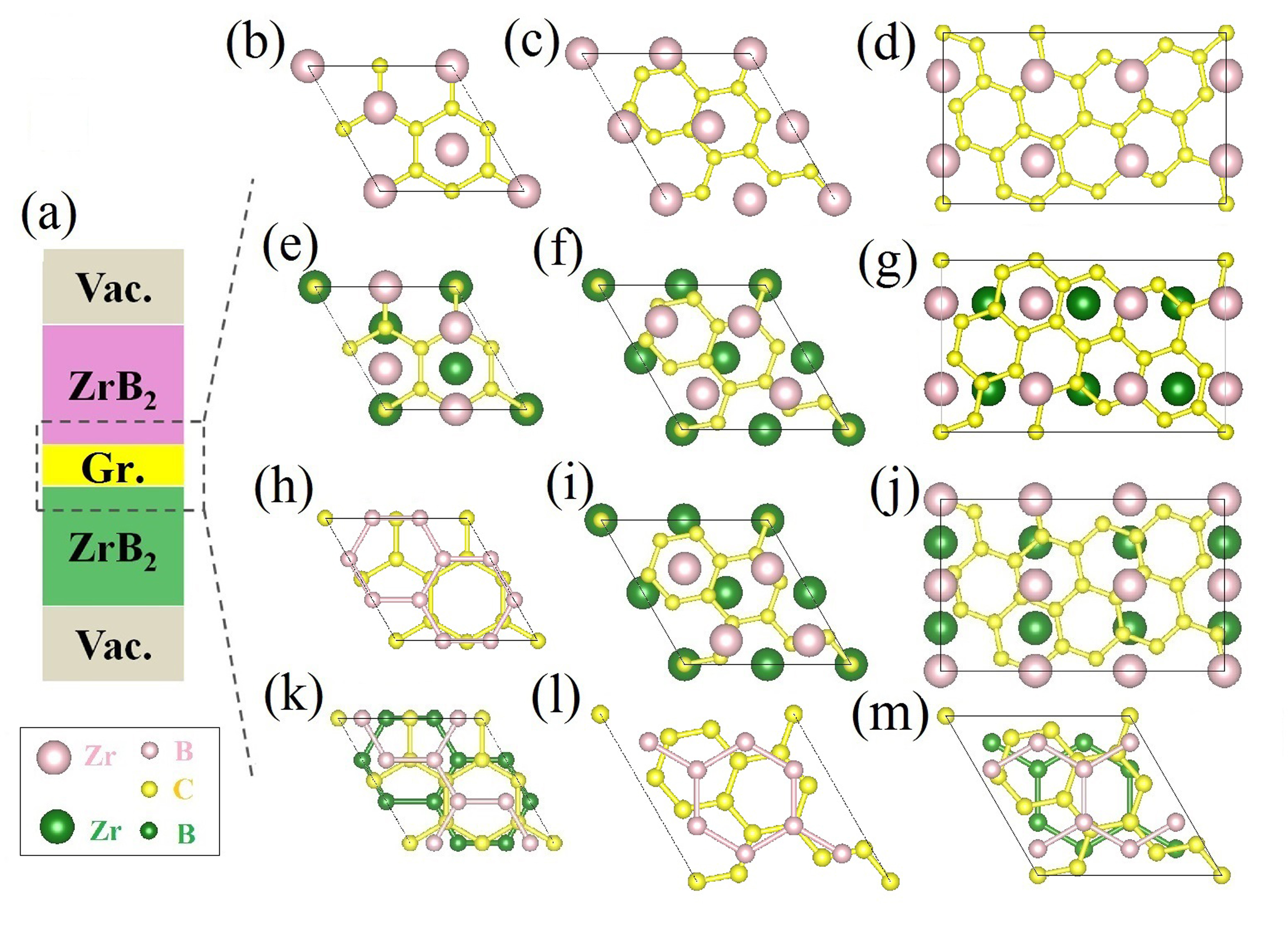
Taking all this into consideration our notation used to describe the hybrid structures is based on 1) the supercell types, 2) the atomic species facing at the interface, and 3) the stacking sequence. For example, II, II and II describe the interface models having type II supercell, Zr-C-Zr facing species and the stacking sequences AA, AB and AC, respectively. The top view of their interface regions are illustrated in the panels (c), (f) and (i) of Fig. 1, which contains the same plots for all the interfaces investigated. To be more specific, the atomic structures of our interface models have the following characteristics:
-
•
I and I [86 atoms with chemical composition (Zr3B6)8C8Zr6] have Zr-C-Zr bonding across both interfaces. They have the same in-plane arrangement as the Ni(111)/graphene interface shown in Fig. 1(b) of Ref. 40. The supercells are made of two fragments of the (0001) ZrB2 slab, sandwiching a graphene monolayer rotated by 30° with respect to the ZrB2 borophene plane [see Figs. 1(b) and 1(e)];
- •
-
•
II, II and II [118 atoms with composition (Zr4B8)8C14Zr8], shown in Figs. 1(c), 1(f) and 1(i), are built from two blocks of the 2 2 (0001) ZrB2 slab and one graphene monolayer. Here, the graphene is rotated by 19.1° with respect to the ZrB2 borophene plane. They have the Zr-C-Zr [0001] stack similarly to I and I. However, the Zr atoms are misaligned with the C atoms in graphene, resulting in a smaller lattice mismatch (2% against 10%);
- •
- •
Finally, the ZrB2/graphene interlayer distance, , and the common lattice parameters ( and ) are optimized by searching for the lowest energy points of the potential energy surface (see section 3.2.1). The so-calculated parameters are tabulated in Table S1 of the supplementary information (SI), together with the in-plane strains. At such optimized lattice parameters the ionic positions are fully relaxed into their ground state by using the quasi-Newton algorithm to relieve the residue stresses.
3.2 Interface Energetics
3.2.1 Interfacial adhesion energy ()
The adhesion energy, , is defined as the energy per unit area released when forming a multi-layered structure from the isolated surface slabs, namely
| (1) |
Here, Etot(ai), Etop(a0), Ebot(a0) and EGr() are, respectively, the total energy of the hybrid structure, that of the top and bottom ZrB2 slab and of the graphene monolayer. Note that the reference ZrB2 slabs have an in-plane lattice parameter, , corresponding to that of their strain-free surface configuration. In contrast the reference graphene monolayer has a C-C bond length of Å. As a consequence of this choice for the various hybrid structures is computed relatively to the same reference states, namely the strain-free surface slabs. An alternative choice is to take the bulk structures as reference, a choice that will include the surface formation energy into the definition of . Finally, is the interface area and the pre-factor 2 takes into account the fact that our hybrid structures have two interfaces.
The calculated curves are presented in Fig. 2(a) for all the three kinds of interface supercells I, II and III, while the interlayer distances, , are kept fixed at 2.5 Å. A parabolic behaviour is observed in all cases, similarly to what recently reported for the interface between graphene and Ti2C MXene 41. The in-plane lattice parameters of the various interfaces are thus determined from the minima of Fig. 2(a). Then the optimal interlayer distances, , are computed by looking at the minima of the curves taken at the optimized , see Fig. 2(b).
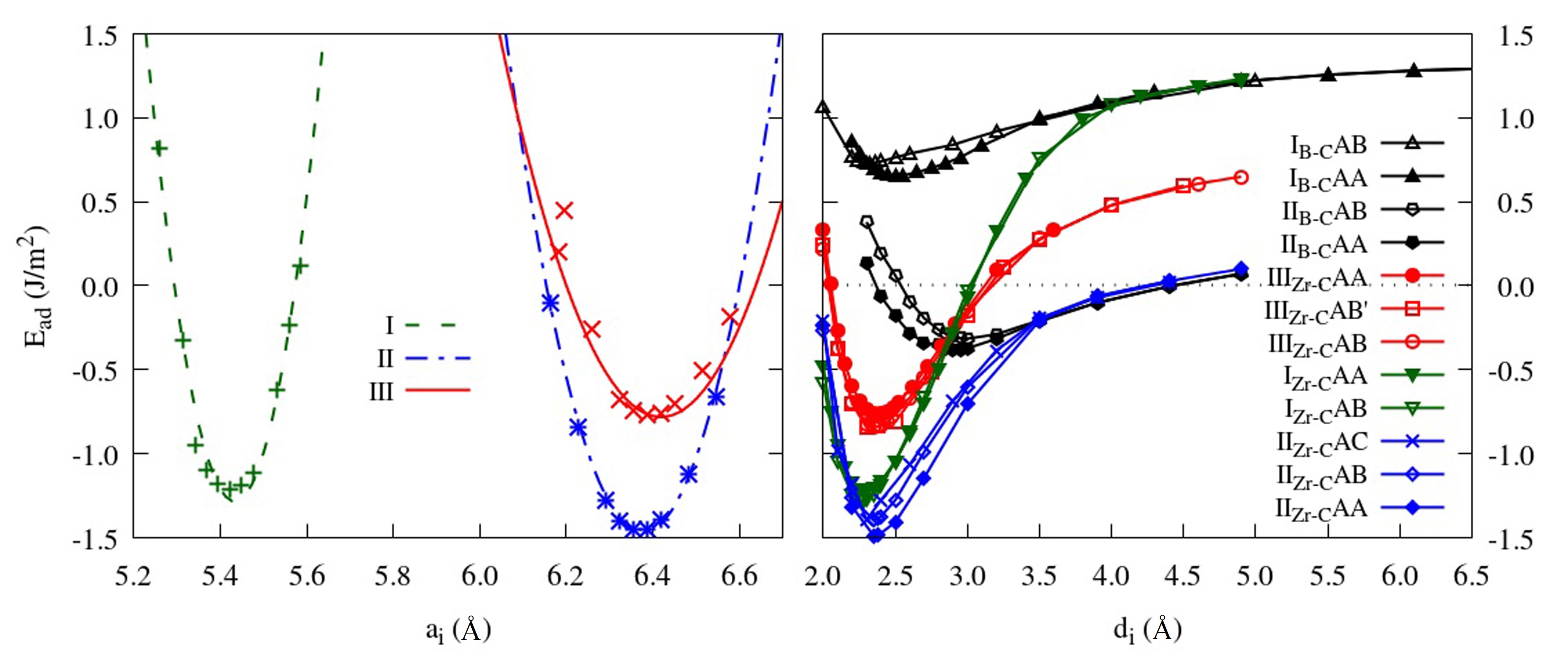
Several comments can be made by looking at Fig. 2(b). Firstly, we note that the overall curves move to a lower energy as we go across the series IB-C, IIB-C, IIIZr-C, IZr-C and IIZr-C. Their thermal stability therefore has to be ranked in the reverse order. Secondly, it is quite clear that all the Zr-C interfaces have a deeper potential well than those with B-C bonding, suggesting that the Zr-C interfaces are energetically more favorable than the B-C ones. Thirdly, we find that the exact stacking order has little effect on the curves, in particular on their energy minimum, indicating that the local bonding environment plays only a minor role in the interface stability. Finally, one has to note that all the curves have a long distance tail that asymptotically converges to a positive value. In particular we have all type I curves converging to J/m2, the type II to J/m2 and the type III to J/m2. Such asymptotic values, , correspond to the misfit strain energies introduced by imposing a common in-plane lattice parameter. Thus the ’s are proportional to the misfit strains associated to the various interface models. In fact the strain energies are ranked in the order , which is the same order of the in-plane strains.
Although it is too computationally expensive to include misfit dislocations in our DFT calculations, because of the large supercells required, the misfit strain can be effectively released by considering configurations where graphene presents vertical corrugation, an intrinsic feature of graphene flakes 42. After full structural relaxation, the Zr-C interfaces with AB and AC stacking orders exhibit a more pronounced graphene corrugation than that corresponding to the AA stacking. In contrast, for B-C interfaces more pronounced graphene rippling is present for the AA order. The underlying mechanisms leading to these structural differences will be analyzed later when discussing the electronic structure of the interfaces.
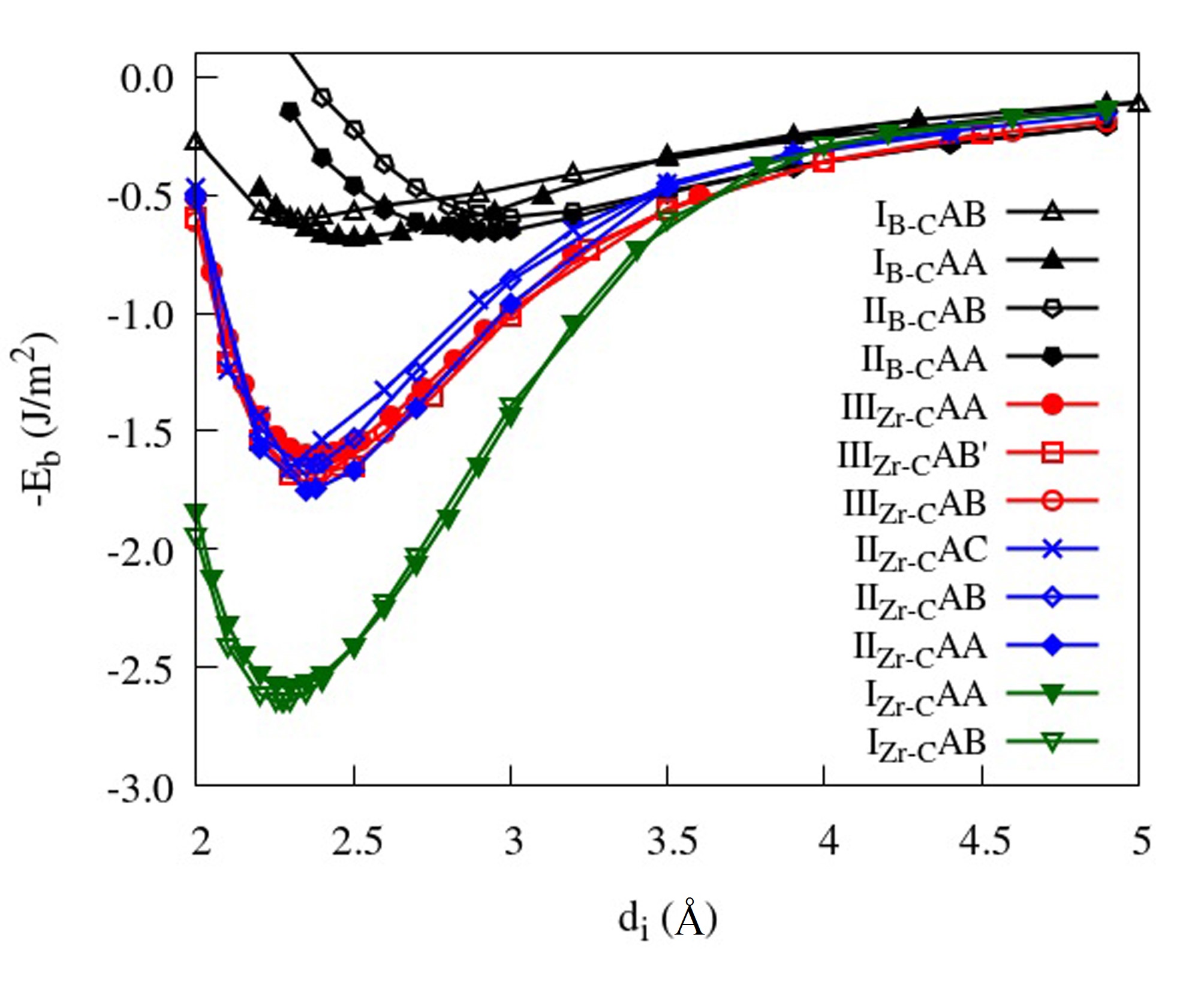
3.2.2 Interfacial binding energy
As discussed before our interface supercells are constructed using the commensurate model so that the heterogeneous layers have common in-plane lattice parameters, a fact that introduces misfit strain. As a consequence, contributions to originating from the misfit strain energy, , add to those coming from the formation of the chemical bond at the interface, . In order to decouple the two contributions, we assume that can be written as
| (2) |
The misfit energy can be approximated by the following expression
| (3) |
where , and are, respectively, the total energy of the top and bottom ZrB2 slab and that of the graphene monolayer. The other terms are the same as mentioned in Eq. (1). Hence one has
| (4) |
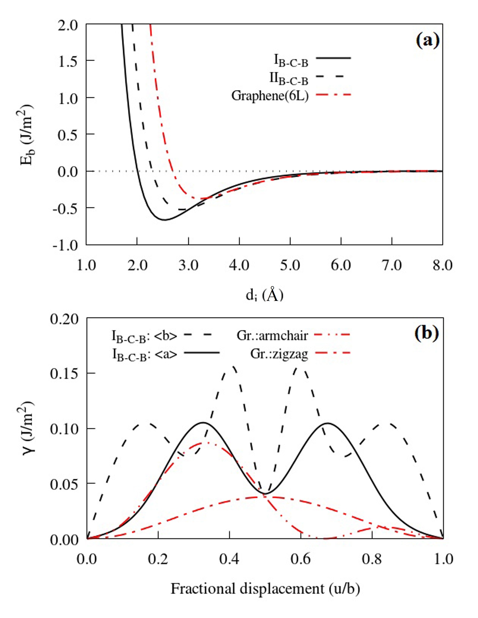
The binding energy curves are then presented in Fig. 3. In comparison of , they all asymptotically converge to zero. Interestingly all the curves seem to cluster into three main groups: (i) the IZr-C interface has the deepest well ( J/m2), indicating strong interfacial interaction; (ii) the interfaces IIZr-C and IIIZr-C have an intermediate minimum at around 1.7 J/m2, which is 35% lower than that of IZr-C, suggesting a moderate interfacial interaction; (iii) all the interfaces of B-C type show a very shallow profile, with a minimum at around 0.5 J/m2. This latter value is close to that calculated for graphite (0.4 J/m2).
It is worthy to mention that and for the B-C interfaces are about one order of magnitude smaller than those of the Zr-C interfaces. Such differences are related to the interfacial bonding mechanism. Our guess is that graphene/borophene layers in the B-C interface are coupled by weak physical adsorption, while the Zr-C interfaces are bonded by strong chemical interaction, similar to that at play in metal/graphene contacts 40. These hypotheses will be investigated further in the electronic structures section 4.1.
In concluding this section we remark our main finding, namely that the interface adhesion energy, , is strongly affected by the chemical species facing each other across the interface. This, however, also includes the misfit strain energy, . When is subtracted from we are left with the interface binding energy, , which ranks the stability of our interface models as I. It is worthy to mention that, besides the thermodynamically stable Zr-C interfaces, also the B-C ones may be relevant for composites, since B-terminated ZrB2 43 can form in B-rich growth conditions.
3.3 Interfacial cleavage
The interfacial fracture behavior is investigated by computing the traction-displacement curves, which are obtained from the derivative of the total energy changes upon displacing two materials adjacent to the interface 44. Calculations are performed for two different displacement modes, namely opening (mode I, the two sides of the interface are displaced orthogonally to the interface plane) and sliding (mode II, the two sides of the interface are displaced along the interface plane). In this section we will present results for the loading mode I, for which we have adopted the same cleavage model of Lazar and Podloucky 45 for bulk materials, while the displacement mode II (sliding) will be discussed in section 3.4. In the fracture mode I the tri-layer structure is separated by introducing an initial displacement of length between the top ZrB2 slab and the graphene layer, so that a pre-existing crack is introduced at one side of the interface. Thus, the inter-layer distances of the graphene layer with the bottom and top ZrB2 slabs are, respectively and , where is the equilibrium interlayer distance calculated before. The corresponding energy change per unit area defines the cleavage energy, , which writes
| (5) |
In Eq. (5) and are the total energies of the pristine hybrid structure and of the cleaved one, respectively.
We have then fitted the curves with a Morse function
| (6) |
where is the work of separation. Here the parameter determines the width of the curve, while controls its curvature at . The traction curve, , is calculated as the first derivative of with respect to
| (7) |
where is in GPa. Then, the interfacial cleavage strength, , and the critical crack length, , are defined as the values of and at the maximum of the curve. The general behaviour of is rather simple. As the pre-opening crack grows ( gets larger), continuously increases until it reaches its maximum value, . Thereafter a crack between free (non-interacting) surfaces is formed. The final separation, , thus can be written as
| (8) |
The typical mode of cleavage used in the calculation is presented in Fig. 4(a), our calculated cleavage energies are shown in Fig. 4(b) for cleaving across the Zr-C and B-C interfaces, and in Fig. 4(c) for cleaving Zr-B and B-B atomic layers in the ZrB2 matrix, while the corresponding traction-separation curves are displayed in Fig. 5. Note that three kinds of structural relaxation strategies are considered when calculating the relevant cleavage quantities, and these are explained in the SI. We start our analysis with the brittle cleavage due to a sharp fracture surface and then we move our attention to the effects of structural relaxation and of the graphene layer corrugation.
Among all the cleavage modes, cleaving B-B bonds along [100] in bulk ZrB2 has the highest value of 10.29 J/m2, while cleaving between Zr and B both along [100] and [0001] has rather similar (9.50 J/m2). In comparison, cleaving across the interfaces with graphene requires works of separation one order of magnitude smaller (values in the range 0.70-1.79 J/m2). This confirms that the ZrB2/graphene interfaces as the weak parts can deflect cracks during the fracture of composites. Such feature allows the energy to be released at the ZrB2/graphene interface, so that the structural integrity of the ZrB2/graphene composite can be preserved.
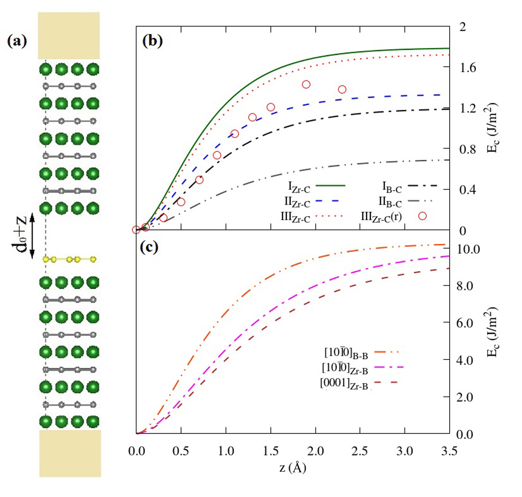
In more detail, both and systematically decrease when going through the interfaces IZr-C, IIIZr-C, IIZr-C, IB-C and IIB-C, namely they follow the ranking obtained from the binding energy curves of Fig. 3. This correspondence was also observed in the past when studying interfaces in lamellar TiAl alloys 46. Since the crack is initiated by breaking the interfacial Zr-C or B-C bonds, it appears that the bonding mechanism across the interfaces is responsible for the interface strength. In other words, the values of , and all reflect the ease of interfacial debonding. Although in real composites additional features, such as defects and impurities, may modify the strength of the interfacial interaction and then affect the way of crack propagation, the ranking calculated here already provides a clear map of the mechanical stability of the various components of a graphene/ZrB2 composite.
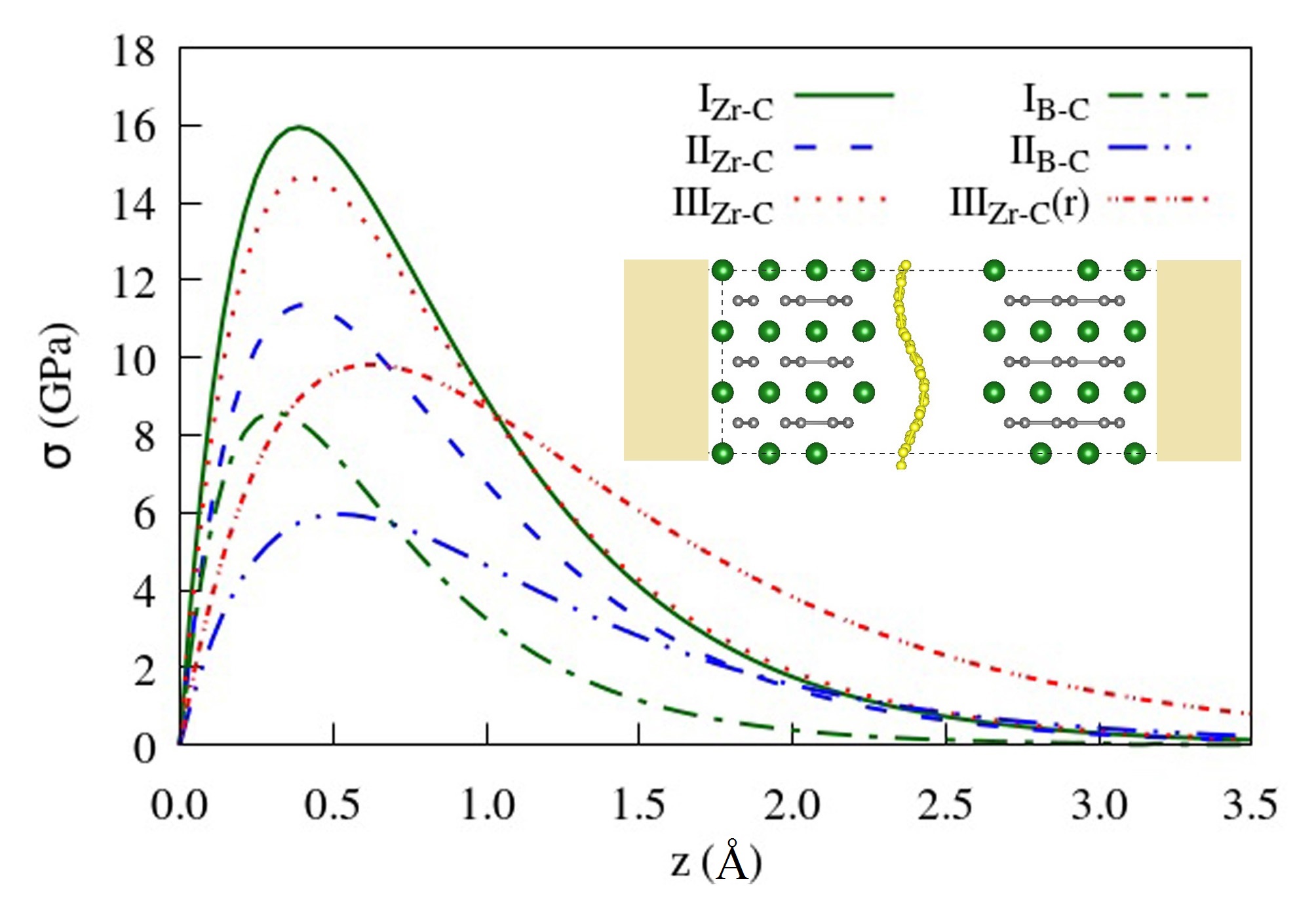
Several important parameters, such as the work of separation, , the traction strength, , the critical separation, , and the final separation, , can all be extracted from these curves and are summarized in Table 1. These quantities, together with the shear parameters presented in Table 1, can then be used as inputs in continuum simulation models of cohesive zone to provide a complete understanding of the interface de-bonding of GCMC materials. It is worth mentioning that the varies from 15.95 GPa to 4.02 GPa when going from IZr-C to IIB-C. This provides a chance of tuning the mechanical behavior of interfaces in GCMCs over one order of magnitude.
| Mode I loading (opening) | (J/m2) | (GPa) | (Å) | (Å) | |
| ZrB2 | [100]B-B | 10.29 | 82.16 | 0.43 | 2.50 |
| [100]Zr-B | 9.97 | 56.06 | 0.62 | 3.56 | |
| [0001]Zr-B | 9.38 | 49.54 | 0.66 | 3.79 | |
| Graphene | [0001]C-C | 0.36 | 2.27 | 0.55 | 3.17 |
| Interfaces | IZr-C | 1.79 | 15.95 | 0.39 | 2.24 |
| IIIZr-C | 1.73 | 14.67 | 0.41 | 2.35 | |
| IIZr-C | 1.33 | 11.34 | 0.41 | 2.35 | |
| IB-C | 1.20 | 8.96 | 0.46 | 2.68 | |
| IIB-C | 0.85 | 4.02 | 0.73 | 4.23 | |
| Mode II loading (sliding) | (J/m2) | (J/m2) | (GPa) | ||
| ZrB2 | - | 3.47 | 49.62 | ||
| 3.03 | 3.47 | 24.45 | |||
| Graphene | armchair | - | 0.09 | 1.00 | |
| zigzag | - | 0.04 | 0.48 | ||
| Interfaces | IZr-C | - | 0.57 | 4.55 | |
| IZr-C | 0.05 | 0.57 | 8.37 | ||
| IB-C | 0.04 | 0.10 | 1.87 | ||
| IB-C | 0.04 | 0.15 | 3.35 | ||
We have then investigated the effects of the structural relaxation on the energetics of the fracture (a detail discussion is provided in the SI). The atomic positions within a region 4.5 Å vertical to the fracture surfaces are relaxed in order to minimize the internal stresses and the total energy. The results are labelled as IIIZr-C(r) in Figs. 4(b) and 5, while the final geometry is shown in the inset of Fig. 5, where it is evident that relaxation produces a corrugation of the graphene layer. It is experimentally known that graphene sheets may exhibit large corrugations when adsorbed on metal surfaces 42. This is observed here, since the buckling of graphene can efficiently relieve the misfit strains across the interface and provides an energy reduction channel alternative to misfit dislocations. As illustrated in Fig. 4(b) with the open circles, the corrugation of graphene can lower down by 0.4 J/m2. At the same time it makes the critical cleavage stress going from 15 GPa to 10 GPa. This demonstrates that, in general, graphene buckling has the effect of weakening the interface adhesion. The effect originates from the fact that the interface, namely the surface of graphene in direct contact with the ZrB2 surface, is partially detached so that the contact area is reduced by the corrugation. Note that the rippling period of graphene is constrained by the in-plane dimensions of the supercell, and that the III supercell (148 atoms) is the largest studied here. One then has to expect that for planar structures with a larger in-plane cell, and consequently smaller lattice misfit and internal stress, the effect of graphene buckling will be in general less pronounced.
3.4 Interface sliding
Interfacial sliding processes are studied in order to extract the traction-separation curves under the loading mode II 44. This is modelled by displacing the top ZrB2 slab along a direction parallel to the interface plane, while monitoring the total energy as a function of the sliding vectors. The sliding profile, , can be defined as the change in total energy with respect to the energy of the undistorted structure as a function of the sliding vector, namely
| (9) |
where and are the total energies of the undistorted and of the distorted structure, respectively.
The rigid energy landscape is derived by monitoring the energy of the distorted structure without performing any structural relaxation. In addition, we have also calculated the effects of full structural relaxation by using the nudged elastic band (NEB) method 47, 48. In practice we allow atomic relaxation both perpendicular to the gliding plane and in-plane and track the minimum energy path (MEP) while keeping the Burgers vectors fixed. This fully relaxed calculations have been performed only for the interface models IZr-C (86 atoms in the supercell) and IB-C (89 atoms). As for the interface types II and III (118 and 148 atoms, respectively), only the rigid sliding profiles have been studied because of the heavy computational costs associated to the DFT-based NEB method. The shear stress along a given direction is then calculated as the slope of the energy profile along that direction, namely
| (10) |
where the maximum is defined as the interfacial shear strength, .
Five slip systems, namely basal a: (0001)20, basal b: (0001)100, prismatic a: (100)20, prismatic c: (100)0001 and prismatic a+c: (100)113, are studied. These all concern interfaces of type I and III with [0001] and [100] orientation. The equilibrium geometry of the Zr-C interfaces has an AB stacking sequence, while that of the B-C structure is AA type. The top panels of Fig. 6 displays the energy profiles for rigid sliding along the Zr-C interfaces. In general the energy barriers are observed to be relatively small in magnitude ( J/m2). In addition we find that the sliding curves present a number of maxima and minima, marked in the figure by arrows. These correspond to different stacking configurations of the supercell (also indicated in the figure), which are connected by the sliding process. As the different stacking orders have a rather similar binding energy (see Section 3.2.2), we expect the sliding energy profile to be relatively shallow, as confirmed by our calculations.
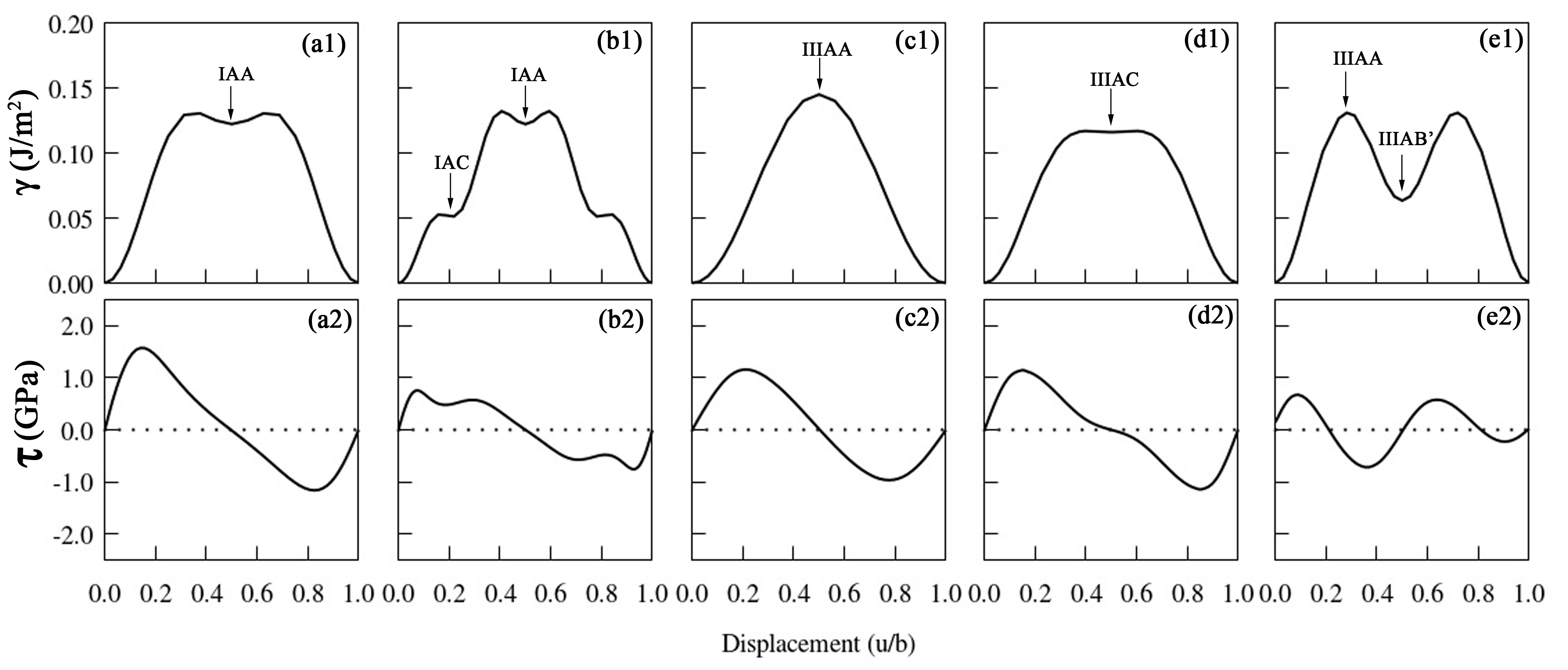
Then, the traction curves for mode II are derived as numerical derivative of the corresponding sliding energy profiles and they are presented in the bottom panels of Fig. 6. For the basal sliding, namely the slips along and of interface IZr-C, the shear strengths are calculated as 1.47 GPa and 0.74 GPa, respectively. In contrast, those along , and for interface IIIZr-C are, respectively, 1.15 GPa, 1.13 GPa and 0.66 GPa. Therefore, the slip system {100} is prone to be activated first. The easy activation of the {100} slip system was previously reported for bulk ZrB2 at over 700C 49. The interfacial sliding along of IZr-C shows comparable shear strengths with those of and of IIIZr-C, although the latter two exhibit slightly lower values.
In order to trace the the sliding energy profile along the minimum energy path, we perform full relaxation calculations using the NEB method. This also allows us to extract some key shear parameters. The energy maximum, namely the unstable stacking fault energy, , governs the dislocation nucleation at sites of stress concentrations such as at the crack tips. The metastable points (local energy minima) correspond to stable stacking faults with their energies, , determining the dislocation core dissociation, the Peierls stress, the dislocation energy, and the primary slip planes. These shear parameters ( and ) are summarized in Table 1.
The relaxed sliding energy profiles are then shown in Figs. 7(a) and 7(b) for the interfaces IZr-C and IB-C, respectively. Let us look at the IZr-C case [panel (a)] first. We find that for both the basal and shear is 0.57 J/m2, a value that is almost four times larger than those obtained for rigid shearing. This increase is due to the atomic rearrangement, especially the out-of-plane corrugation of the graphene layer, which effectively obstructs the interfacial sliding. In order to understand such dramatic increase we note that the total energy reduction due to atomic relaxation differs depending on the precise stacking order. In the case of Zr-C interface, the AB stacking corresponds to the initial position of its sliding energy landscape (see Fig. 6), which shows a deeper energy well after atomic relaxation since some of the stress is released. In contrast, the AA configuration is at a peak of the curve and it is relatively stress-free. As a consequence atomic relaxation has little effect on its energetics. Thus, the final result of the relaxation is that of increasing the energy barrier, . This suggests that the rôle of corrugated graphene is twofold. On the one hand, it reduces the interface adhesion strength during interface debonding, on the other hand it increases the interfacial friction during the sliding process.
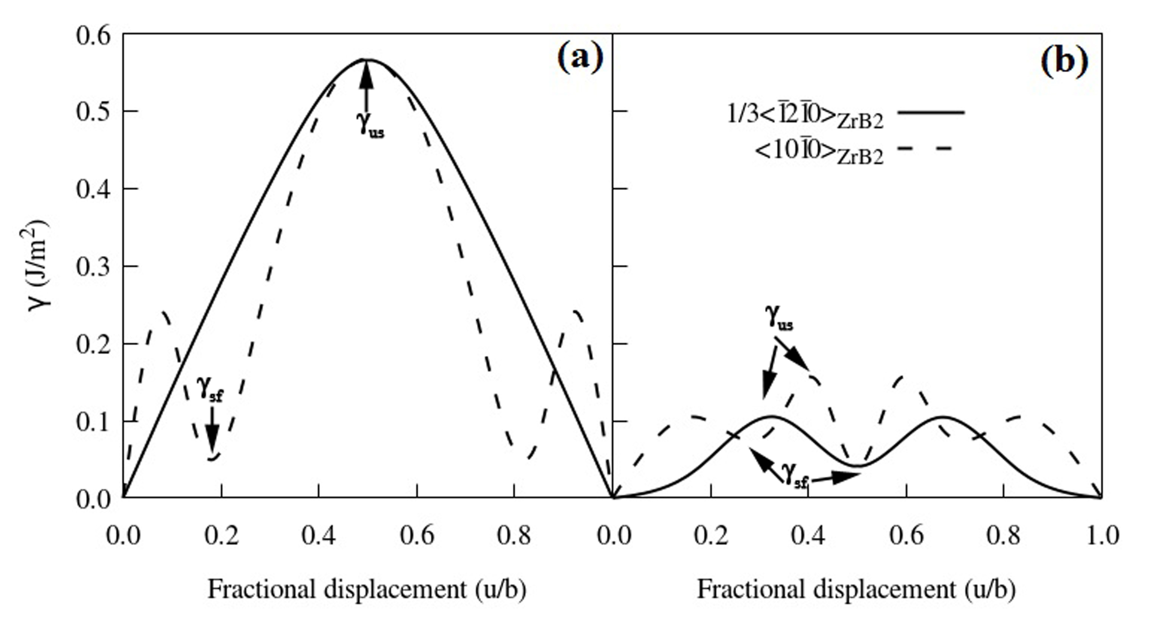
As for the IB-C interface, we note that the values (0.10-0.15 J/m2) are similar to those calculated without performing atomic relaxation. Now is four times smaller than that of IZr-C. This is the result of the shallow surface of the IB-C interface, consistent with the ranking given before for the adhesive and binding energies. Since the B-C interfaces are bonded by weak physical adsorption (see later discussion), also their low energy states have the symmetric AA stacking, rather than the non-symmetric AB or AC ones. Graphene corrugation has little effect on the interfacial sliding of B-C interfaces, when compared to the case of Zr-C interfaces. We then conclude that the B-C interfaces are much more favourable for sliding that the more adhesive Zr-C ones.
Finally, we compare the ideal shear strength of Zr-C and B-C interfaces with the ZrB2 matrix. The calculated for IZr-C are 4.55 GPa and 8.37 GPa, when sliding respectively along and . The same quantities are reduced to 1.87 GPa and 3.35 GPa for the corresponding IB-C interface and they are increased to 49.62 GPa and 24.45 GPa for bulk ZrB2. Thus the interfacial shear strength of ZrB2/graphene interfaces is at least one order of magnitude lower than those of the ZrB2 matrix and the same observation is valid for the cleavage strength. This suggests that the -surfaces are much less corrugated at a heterophase interface, which indicates relatively ease of interfacial sliding. When examining specific interfaces, it is clear that IB-C is more prone to host deformation pathways, than IZr-C.
4 Discussion
4.1 Interfacial bonding mechanism
One of the main result from the previous sections is that the Zr-C and B-C interfaces present very different strengths of adhesion and binding, as well as the traction curves under the two loading modes investigated. This suggests that different bonding mechanisms are at play in these two interfaces. Here, we analyse the interfacial interaction by looking at the projected density of states (PDOSs) and the projected charge density, as shown in Figs. 8(a) through 8(c).
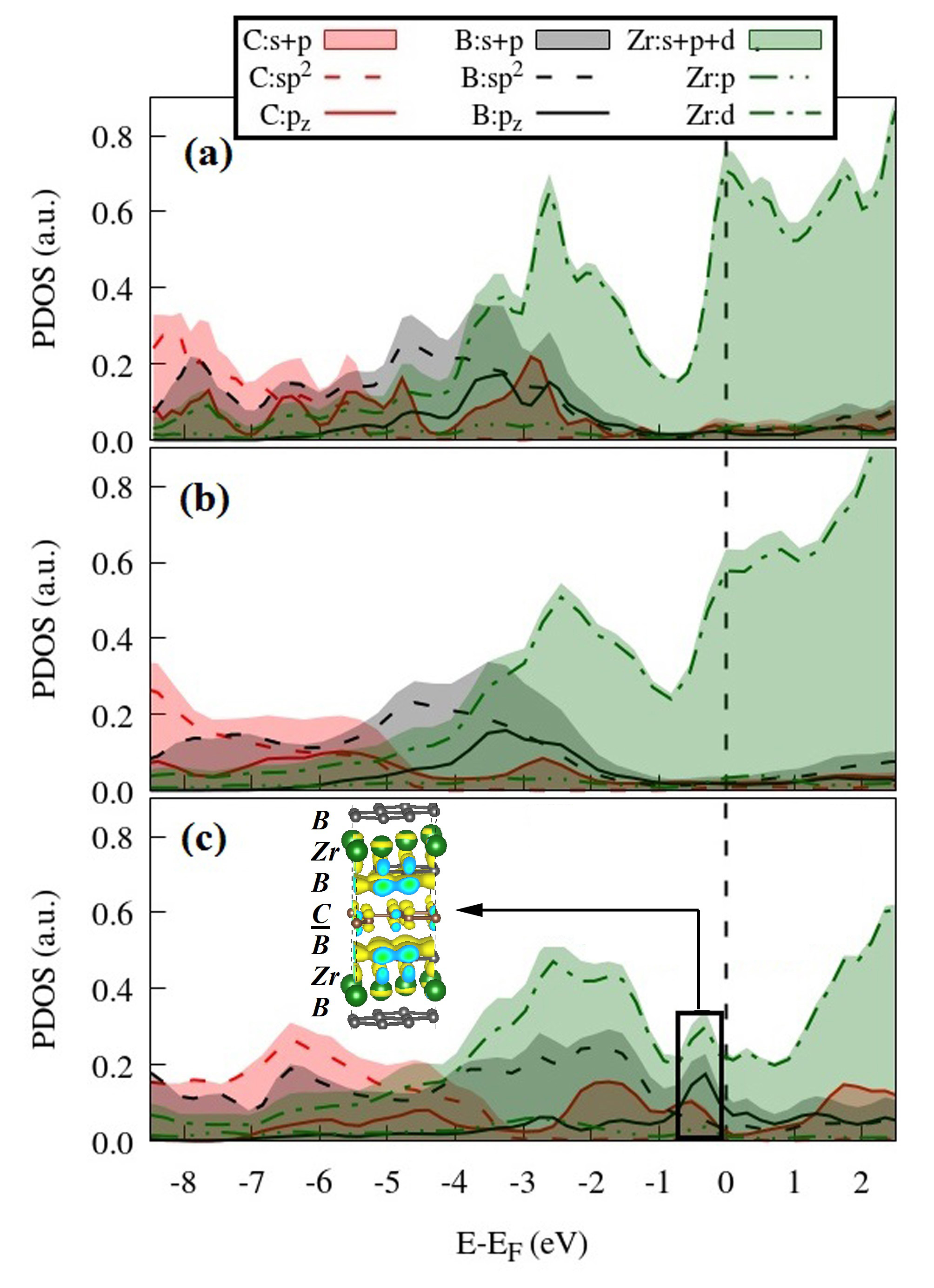
As expected, the partially filled Zr bands dominate the PDOS for energies starting at 4 eV below the Fermi level, , and they represent the main contribution to the Fermi surface for Zr-C interfaces [see Fig. 8(a) and 8(b)]. In this case a distinctive feature is the appearance of a PDOS reduction at about 1 eV below , which separates a region ( eV) with little contribution from either B or C, from another region ( eV), where the PDOS from the C 2 orbital is significant. This is a clear signature of the strong hybridization between the C 2 and the Zr 4 orbitals, and the consequent formation of Zr-C covalent bonds. Such attribution is consistent with the strong affinity between Zr and C and the existence of covalent ZrC1-x compounds. Covalent bonding across interfaces has also been suggested for the interfaces of Ti2C/graphene 41, ZrC/SiC 50 and metal graphene contacts 40.
Across the Zr-C interfaces the electron-acceptor B ions (with valence configuration ) are replaced by C (). This effectively shifts the Fermi level upwards in energy, and in fact the PDOS pseudogap moves from in bulk ZrB2 to 0.8 eV below at the Zr-C interface. The effective charges, as calculated from Bader analysis, of Zr and B in bulk ZrB2 are +1.54 and -0.77 ( is the electron charge) 51. These become +1.23 (Zr) and -0.35 (C) at the Zr-C interface, suggesting that the Zr-C bond has a mixture of ionic and covalent nature.
The situation for the B-C interfaces is rather different, as one can easily conclude by looking at Fig. 8(c). In this case the most prominent feature of the DOS is a peak just below the Fermi level, with significant projections originating from the B and C 2 orbitals. This suggests that the bonding has a - stacking nature, a fact that is confirmed by the projected charge density shown in the inset of Fig. 8(c). Such - interaction is commonly present in aromatic compounds 52.
As expected from elementary chemistry the B-C - interaction is weaker than the covalent bond between Zr and C, as shown by our previous calculations of the mechanical properties of the various interfaces. However, such - interaction is still stronger than the van der Waals coupling between graphene layers in graphite and, in general, among monolayers of van der Waals layered compounds. This is demonstrated in Fig. 9(a), where we compare the binding energy curves, , of the B-C interfaces with that of graphite. The binding energies are calculated to be 0.488 J/m2 and 0.663 J/m2 for IB-C and IIB-C, respectively. In contrast we compute J/m2 for a 6-layer graphene nanosheet. In addition the equilibrium interlayer distance at the B-C interfaces is between 2.5 Å and 3.0 Å, while that in graphite is 3.23 Å. The - stacking interaction here is made stronger than that in graphite by two features of the electronic structure: 1) the electrostatic interaction between the negatively charged C and the positively charged B atoms ; 2) the offset stacking of the borophene and graphene layers contributing to reduce the repulsive interaction. Since the van der Waals interaction among the graphene sheets is believed to be the reason behind its agglomeration in composites 53, the stronger adhesion between boraphene and graphene can be exploited as a tool for breaking the agglomeration and promoting a more uniform dispersion of graphene nanofillers in ceramic matrices. This can be beneficial to the improvements of the overall structural stability and functionality of the nanocomposites.
Interestingly, the - bonding mechanism across the B-C interfaces gives to these interfaces mechanical properties analogous to those of 2D materials. This is illustrated in Fig. 9(b), where we compare the sliding curves of the two IB-C interfaces with those calculated for graphene. We find that the values for graphene are 0.04 J/m2 and 0.09 J/m2, respectively for shearing along the zigzag and armchair edges. The slipping along the basal and directions returns the values of 0.10 J/m2 and 0.15 J/m2, respectively, which are comparable to those of graphene.
4.2 Interfacial mechanics
In the previous sections we have observed a large difference between the Zr-C and the B-C interface with respect to their adhesive and mechanical properties. In particular the Zr-C interfaces display stronger adhesion, cleavage and shear strength than those of B-C interfaces. This can be well explained by the difference in interfacial bonding mechanism, which is covalency-dominated in Zr-C and --stacking type in B-C interfaces. The stronger Zr-C interfaces thus present high resistance to both cracks and interfacial sliding, while the weak B-C interfaces are much more easy to allow interfacial debonding and shear.
The ZrB2 matrices, have a rich variety of stable surfaces, either Zr-, B- or mix-terminated surfaces with different orientations. They can be somehow engineered by acting on the ZrB2 growth conditions. Note the existence of the Zr/B-terminated (0001) surface has been confirmed by both experiments 43, 37, 38 and theory 54, 35. The (0001) surfaces with Zr/B-terminations emphasized here are the two extreme cases, which exhibit completely different mechanical behavior. In general, Zr-C interfaces can be prepared by stabilising the Zr-terminated surfaces in Zr-rich conditions. While a B-rich environment will favour the formation of B-C interfaces. Therefore, surface chemistry can be used as an efficient tool for tailoring the interfacial mechanics by tuning the surface contacts.
It is important to note that the toughening effect of graphene fillers is correlated with the interface debonding mechanism. Since in composites the interfacial debonding will favour the dissipation of energy via crack bridging, crack deflection and fillers pulling-out, the predominance of a mechanism over the others will affect the crack propagation behavior along various interfaces, so that different ZrB2 growth conditions may result in tuning possibility of the mechanical properties of GCMCs. This observation also provides hints on why there is a wide variation of the fracture-toughness-parameter values in experiments on graphene-reinforced composites 55.
Last but not least, monolithic ZrB2 and graphene nanoplatelets are used as starting materials during spark plasma sintering 7 of ZrB2/graphene composites. The nanoplatelets are made of short stacks of ribbon-shaped graphene sheets. These are functionalised with groups like ethers, carboxyls or hydroxyls, which may further modify the interfacial bonding 56. Therefore, a scrupulously designed surface treatment is vital for the accurate control of the interfacial interaction, and hence of the interface mechanics and the failure mode. Our theoretical results suggest that the preferred interface mechanics can be engineered by acting on the interfacial interactions through the tuning of the surface chemistry of ZrB2 and graphene.
5 Conclusion
In this work we have studied the heterophase interfaces of graphene-reinforced ZrB2 composites based on DFT calculations. A number of atomistic models for the various possible interfaces has been constructed by using the most thermodynamically stable surfaces of the ZrB2 matrix. Then, we have systematically investigated their interface adhesion, mechanical behaviour and bonding mechanism. We have demonstrated that two kinds of interfaces, namely Zr-C-Zr and B-C-B, offer a wide spectrum of mechanical properties due to their dissimilar interaction between the constituent materials. In particular Zr-terminated surfaces bind to graphene in a covalent way, while the interaction with the borophene planes in ZrB2 has a --stacking nature. By tuning the surface chemistry of the ZrB2 matrix one can prepare composites that expose graphene predominantly to a specific ZrB2 termination (either Zr or B or mixed), so it is possible to go from a regime of weak graphene/matrix interaction to one where the interaction is relatively strong. This provides an important design scheme in the synthesis of ceramic composites. Furthermore, the fact that the borophene/graphene interface is more adhesive than the graphene/graphene one may offer an opportunity to tackle flakes agglomeration, a issue encountered when processing most graphene-reinforced composites. Finally, we have analysed the rôle of graphene rippling over the mechanical properties of the interfaces. Interestingly we have found that rippling drastically increases the friction for sliding graphene over ZrB2 in the case of Zr termination, while it has no significant effect for that with B termination.
This work is supported by the European Union’s Horizon 2020 “Research and innovation programme” under the grant agreement No. 685594 (C3HARME). Computational resources have been provided by the Irish Center for High-End Computing (ICHEC) and the Trinity Centre for High Performance Computing (TCHPC). The authors also thank Rui Dong for the clattice code used to merge surface slabs.
The Supporting Information is available free of charge on the ACS Publications website for: Geometry details of interface models, Structural relaxation effects on interfacial cleavage.
References
- Kinloch et al. 2018 Kinloch, I. A.; Suhr, J.; Lou, J.; Young, R. J.; Ajayan, P. M. Composites with carbon nanotubes and graphene: An outlook. Science (80-. ). 2018, 553, 547–553
- Porwal et al. 2013 Porwal, H.; Grasso, S.; Reece, M. J. Review of graphene–ceramic matrix composites. Adv. Appl. Ceram. 2013, 112, 443–454
- Singh et al. 2011 Singh, V.; Joung, D.; Zhai, L.; Das, S.; Khondaker, S. I.; Seal, S. Graphene based materials: Past, present and future. Prog. Mater. Sci. 2011, 56, 1178–1271
- Walker et al. 2011 Walker, L. S.; Marotto, V. R.; Rafiee, M. A.; Koratkar, N.; Corral, E. L. Toughening in Graphene Ceramic Composites. ACS Nano 2011, 5, 3182–3190
- Tao et al. 2017 Tao, L.; Theruvakkattil Sreenivasan, S.; Shahsavari, R. Interlaced, Nanostructured Interface with Graphene Buffer Layer Reduces Thermal Boundary Resistance in Nano/Microelectronic Systems. ACS Appl. Mater. Interfaces 2017, 9, 989–998
- Gao et al. 2017 Gao, C.; Feng, P.; Peng, S.; Shuai, C. Carbon nanotube, graphene and boron nitride nanotube reinforced bioactive ceramics for bone repair. Acta Biomater. 2017, 61, 1–20
- Yadhukulakrishnan et al. 2013 Yadhukulakrishnan, G. B.; Karumuri, S.; Rahman, A.; Singh, R. P.; Kaan Kalkan, A.; Harimkar, S. P. Spark plasma sintering of graphene reinforced zirconium diboride ultra-high temperature ceramic composites. Ceram. Int. 2013, 39, 6637–6646
- An et al. 2016 An, Y.; Han, J.; Zhang, X.; Han, W.; Cheng, Y.; Hu, P.; Zhao, G. Bioinspired high toughness graphene/ZrB2 hybrid composites with hierarchical architectures spanning several length scales. Carbon N. Y. 2016, 107, 209–216
- An et al. 2016 An, Y.; Xu, X.; Gui, K. Effect of SiC whiskers and graphene nanosheets on the mechanical properties of ZrB2-SiCw-Graphene ceramic composites. Ceram. Int. 2016, 42, 14066–14070
- Miranzo et al. 2013 Miranzo, P.; Ramírez, C.; Román-Manso, B.; Garzón, L.; Gutiérrez, H. R.; Terrones, M.; Ocal, C.; Osendi, M. I.; Belmonte, M. In situ processing of electrically conducting graphene/SiC nanocomposites. J. Eur. Ceram. Soc. 2013, 33, 1665–1674
- Nieto et al. 2013 Nieto, A.; Lahiri, D.; Agarwal, A. Graphene NanoPlatelets reinforced tantalum carbide consolidated by spark plasma sintering. Mater. Sci. Eng. A 2013, 582, 338–346
- Liu et al. 2016 Liu, J.; Yang, Y.; Hassanin, H.; Jumbu, N.; Deng, S.; Zuo, Q.; Jiang, K. Graphene–Alumina Nanocomposites with Improved Mechanical Properties for Biomedical Applications. ACS Appl. Mater. Interfaces 2016, 8, 2607–2616
- Liu et al. 2013 Liu, B.; Wang, J.; Li, F.; Sun, L.; Wang, J.; Zhou, Y. Investigation of native point defects and nonstoichiometry mechanisms of two yttrium silicates by first-principles calculations. J. Am. Ceram. Soc. 2013, 96, 3304–3311
- Picot et al. 2017 Picot, O. T.; Rocha, V. G.; Ferraro, C.; Ni, N.; D’Elia, E.; Meille, S.; Chevalier, J.; Saunders, T.; Peijs, T.; Reece, M. J.; Saiz, E. Using graphene networks to build bioinspired self-monitoring ceramics. Nat. Commun. 2017, 8, 14425
- Ru et al. 2018 Ru, J.; Fan, Y.; Zhou, W.; Zhou, Z.; Wang, T.; Liu, R.; Yang, J.; Lu, X.; Wang, J.; Ji, C.; Wang, L.; Jiang, W. Electrically Conductive and Mechanically Strong Graphene/Mullite Ceramic Composites for High-Performance Electromagnetic Interference Shielding. ACS Appl. Mater. Interfaces 2018, 10, 39245–39256
- Sciti et al. 2018 Sciti, D.; Silvestroni, L.; Monteverde, F.; Vinci, A.; Zoli, L. Introduction to H2020 project C3HARME – next generation ceramic composites for combustion harsh environment and space. Adv. Appl. Ceram. 2018, 117, s70–s75
- Padture 2016 Padture, N. P. Advanced structural ceramics in aerospace propulsion. Nat. Mater. 2016, 15, 804–809
- Dai and Zhou 2017 Dai, F.-Z.; Zhou, Y. Reducing the Ideal Shear Strengths of ZrB2 by High Efficient Alloying Elements (Ag, Au, Pd and Pt). Sci. Rep. 2017, 7, 43416
- Zoli et al. 2018 Zoli, L.; Vinci, A.; Galizia, P.; Melandri, C.; Sciti, D. On the thermal shock resistance and mechanical properties of novel unidirectional UHTCMCs for extreme environments. Sci. Rep. 2018, 8, 1–9
- Hu et al. 2009 Hu, P.; Guolin, W.; Wang, Z. Oxidation mechanism and resistance of ZrB2–SiC composites. Corros. Sci. 2009, 51, 2724–2732
- Sarker et al. 2018 Sarker, F.; Karim, N.; Afroj, S.; Koncherry, V.; Novoselov, K. S.; Potluri, P. High-Performance Graphene-Based Natural Fiber Composites. ACS Appl. Mater. Interfaces 2018, 10, 34502–34512
- Hatta et al. 2005 Hatta, H.; Goto, K.; Aoki, T. Strengths of C/C composites under tensile, shear, and compressive loading: Role of interfacial shear strength. Compos. Sci. Technol. 2005, 65, 2550–2562
- Sheldon and Curtin 2004 Sheldon, B. W.; Curtin, W. A. Nanoceramic composites: Tough to test. Nat. Mater. 2004, 3, 505–506
- Kabel et al. 2018 Kabel, J.; Hosemann, P.; Zayachuk, Y.; Armstrong, D. E. J.; Koyanagi, T.; Katoh, Y.; Deck, C. Ceramic composites: A review of toughening mechanisms and demonstration of micropillar compression for interface property extraction. J. Mater. Res. 2018, 33, 424–439
- Salehinia et al. 2015 Salehinia, I.; Shao, S.; Wang, J.; Zbib, H. M. Interface structure and the inception of plasticity in Nb/NbC nanolayered composites. Acta Mater. 2015, 86, 331–340
- Kayser and Adnan 2018 Kayser, M. R.; Adnan, A. Grain boundary driven mechanical properties of ZrB2 and ZrC-ZrB2 nanocomposite: A molecular simulation study. J. Am. Ceram. Soc. 2018, 101, 3105–3117
- An et al. 2015 An, Y. M.; Zhang, X. H.; Han, W. B.; Hu, P.; Chen, G. Q.; Zhao, G. D. Interface of Graphene/ZrB2 Ceramics Structure by Molecular Dynamics Simulation. Key Eng. Mater. 2015, 655, 82–86
- Shahsavari 2018 Shahsavari, R. Intercalated Hexagonal Boron Nitride/Silicates as Bilayer Multifunctional Ceramics. ACS Appl. Mater. Interfaces 2018, 10, 2203–2209
- Shi et al. 2017 Shi, L.; Xu, A.; Zhao, T. First-Principles Investigations of the Working Mechanism of 2D h-BN as an Interfacial Layer for the Anode of Lithium Metal Batteries. ACS Appl. Mater. Interfaces 2017, 9, 1987–1994
- Zhu et al. 2015 Zhu, Y.; He, X.; Mo, Y. Origin of Outstanding Stability in the Lithium Solid Electrolyte Materials: Insights from Thermodynamic Analyses Based on First-Principles Calculations. ACS Appl. Mater. Interfaces 2015, 7, 23685–23693
- Blöchl 1994 Blöchl, P. E. Projector augmented-wave method. Phys. Rev. B 1994, 50, 17953–17979
- Kresse and Joubert 1999 Kresse, G.; Joubert, D. From ultrasoft pseudopotentials to the projector augmented-wave method. Phys. Rev. B 1999, 59, 1758–1775
- Perdew et al. 1996 Perdew, J. P.; Burke, K.; Ernzerhof, M. Generalized gradient approximation made simple. Phys. Rev. Lett. 1996, 77, 3865–3868
- Grimme. 2006 Grimme., S. Semiempirical GGA-type density functional constructed with a long-range dispersion correction. J. Comput. Chem. 2006, 27, 1787–1799
- Zhang and Sanvito 2018 Zhang, Y.; Sanvito, S. First-principles investigation of the thermodynamic stability of MB2 materials surfaces ( M = Ti / Zr / Hf ). J. Am. Ceram. Soc. 2018, 101, 4118–4127
- Chen et al. 2013 Chen, X.; Tian, F.; Persson, C.; Duan, W.; Chen, N. Interlayer interactions in graphites. Sci. Rep. 2013, 3, 3046
- Tengdelius et al. 2016 Tengdelius, L.; Lu, J.; Forsberg, U.; Li, X.; Hultman, L.; Janzén, E.; Högberg, H. ZrB2 thin films deposited on GaN(0001) by magnetron sputtering from a ZrB2 target. J. Cryst. Growth 2016, 453, 71–76
- Stewart et al. 2015 Stewart, D. M.; Frankel, D. J.; Lad, R. J. Growth, structure, and high temperature stability of zirconium diboride thin films. J. Vac. Sci. Technol. A 2015, 33, 31505
- Koda et al. 2016 Koda, D. S.; Bechstedt, F.; Marques, M.; Teles, L. K. Coincidence Lattices of 2D Crystals: Heterostructure Predictions and Applications. J. Phys. Chem. C 2016, 120, 10895–10908
- Giovannetti et al. 2008 Giovannetti, G.; Khomyakov, P. A.; Brocks, G.; Karpan, V. M.; Brink, J. V. D.; Kelly, P. J. Doping Graphene with Metal Contacts. Phys. Rev. Lett. 2008, 101, 026803
- Paul et al. 2017 Paul, P.; Chakraborty, P.; Das, T.; Nafday, D.; Saha-Dasgupta, T. Properties at the interface of graphene and Ti2C MXene. Phys. Rev. B 2017, 96, 1–8
- Meyer et al. 2007 Meyer, J. C.; Geim, A. K.; Katsnelson, M. I.; Novoselov, K. S.; Booth, T. J.; Roth, S. The structure of suspended graphene sheets. Nature 2007, 446, 60
- Aizawa et al. 2008 Aizawa, T.; Suehara, S.; Hishita, S.; Otani, S. Surface phonon dispersion of ZrB2(0001)sqrt{3} x sqrt {3}_B. J. Phys. Condens. Matter 2008, 20, 265006
- Jiang et al. 2010 Jiang, Y.; Wei, Y.; Smith, J. R.; Hutchinson, J. W.; Evans, A. G. First principles based predictions of the toughness of a metal/oxide interface. Int. J. Mater. Res. 2010, 101, 8–15
- Lazar and Podloucky 2008 Lazar, P.; Podloucky, R. Cleavage fracture of a crystal: Density functional theory calculations based on a model which includes structural relaxations. Phys. Rev. B 2008, 78, 104114
- Kanani et al. 2014 Kanani, M.; Hartmaier, A.; Janisch, R. Interface properties in lamellar TiAl microstructures from density functional theory. Intermetallics 2014, 54, 154–163
- Henkelman et al. 2000 Henkelman, G.; Uberuaga, B. P.; Jonsson, H. A climbing image nudged elastic band method for finding saddle points and minimum energy paths. J. Chem. Phys. 2000, 113, 9901–9904
- Henkelman and Jonsson 2000 Henkelman, G.; Jonsson, H. Improved tangent estimate in the nudged elastic band method for finding minimum energy paths and saddle points. J. Chem. Phys. 2000, 113, 9978–9985
- Csanádi et al. 2017 Csanádi, T.; Kovalčíková, A.; Dusza, J.; Fahrenholtz, W. G.; Hilmas, G. E. Slip activation controlled nanohardness anisotropy of ZrB2 ceramic grains. Acta Mater. 2017, 140, 452–464
- Xiong et al. 2017 Xiong, H.; Liu, Z.; Zhang, H.; Du, Z.; Chen, C. First principles calculation of interfacial stability, energy and electronic properties of SiC/ZrB2 interface. J. Phys. Chem. Solids 2017, 107, 162–169
- Wang et al. 2013 Wang, B.-T.; Zhang, W.; Li, W.-D. Mechanics, Lattice Dynamics, and Chemical Bonding in ZrB2 and ZrB12 from First-Principles Calculations. Sci. Adv. Mater. 2013, 5, 1916–1921
- Neel et al. 2017 Neel, A. J.; Hilton, M. J.; Sigman, M. S.; Toste, F. D. Exploiting non-covalent interactions for catalyst design. Nature 2017, 543, 637–646
- Verma et al. 2018 Verma, A.; Parashar, A.; Packirisamy, M. Atomistic modeling of graphene/hexagonal boron nitride polymer nanocomposites: a review. Wiley Interdiscip. Rev. Comput. Mol. Sci. 2018, 8
- Suehara et al. 2010 Suehara, S.; Aizawa, T.; Sasaki, T. Graphenelike surface boron layer: Structural phases on transition-metal diborides (0001). Phys. Rev. B 2010, 81, 85423
- Miranzo et al. 2017 Miranzo, P.; Belmonte, M.; Osendi, M. I. From bulk to cellular structures: A review on ceramic/graphene filler composites. J. Eur. Ceram. Soc. 2017, 37, 3649–3672
- Zhang et al. 2018 Zhang, X.; Shi, C.; Liu, E.; Zhao, N.; He, C. Effect of Interface Structure on the Mechanical Properties of Graphene Nanosheets Reinforced Copper Matrix Composites. ACS Appl. Mater. Interfaces 2018, 10, 37586–37601