Phase field modelling of crack propagation in functionally graded materials
Abstract
We present a phase field formulation for fracture in functionally graded materials (FGMs). The model builds upon homogenization theory and accounts for the spatial variation of elastic and fracture properties. Several paradigmatic case studies are addressed to demonstrate the potential of the proposed modelling framework. Specifically, we (i) gain insight into the crack growth resistance of FGMs by conducting numerical experiments over a wide range of material gradation profiles and orientations, (ii) accurately reproduce the crack trajectories observed in graded photodegradable copolymers and glass-filled epoxy FGMs, (iii) benchmark our predictions with results from alternative numerical methodologies, and (iv) model complex crack paths and failure in three dimensional functionally graded solids. The suitability of phase field fracture methods in capturing the crack deflections intrinsic to crack tip mode-mixity due to material gradients is demonstrated. Material gradient profiles that prevent unstable fracture and enhance crack growth resistance are identified: this provides the foundation for the design of fracture resistant FGMs. The finite element code developed can be downloaded from www.empaneda.com/codes.
keywords:
Phase Field , Functionally graded materials , Fracture , Finite element analysis , Damage1 Introduction
Functionally graded materials (FGMs) are multifunctional composites with spatially varying volume fractions of constituent materials. The resulting graded macroproperties enable designers to tailor the microstructure to specific operating conditions, while minimizing problems associated with discrete material interfaces. Potential advantages inherent to the use of FGMs include, among others, enhancing the thermal stress resistance [1, 2], reducing residual stresses [3], and suppressing stress discontinuities at bimaterial interface structures [4, 5]. As a consequence, FGMs have found a wide range of commercial applications including cutting tools, biomedical devices, optical fibers and wear resistant coatings [6, 7]. However, FGMs commonly exhibit brittle fracture, as ceramic materials are one of the most frequently used constituents. Hence, fracture resistance often constitutes the primary design criterion, and a special branch of fracture mechanics has been devoted to investigate failure in this class of materials [8].
Understanding crack initiation and subsequent growth in functionally graded components is hindered by the influence of material in-homogeneity on the crack propagation path. For example, a crack will deviate from the self-similar crack propagation direction in a functionally graded specimen subjected to pure mode I loading if the material gradient is not aligned with the crack. This crack tip mode mixity induced by the spatial variation of material properties leads to complex crack trajectories that are difficult to capture with conventional numerical methods. The vast majority of works have tried to address this challenge by using discrete numerical methods; efforts include the use of remeshing algorithms [9], extended finite element methods (X-FEM) [10, 11, 12], scaled boundary finite element formulations [13], and cohesive zone models [14]. However, these techniques are limited in tracking the crack path topology, particularly in 3D problems. Variational approaches based on energy minimization constitute a promising tool to overcome this limitation and could, therefore, be particularly useful in modelling crack advance in FGMs [15, 16, 17]. Specifically, the phase field method has proven to be a compelling technique in modelling brittle fracture [18, 19], ductile damage [20, 21], fiber cracking and composites delamination [22, 23], and hydrogen embrittlement [24, 25], among other phenomena. We aim at extending this success by presenting a phase field formulation for fracture in compositionally graded materials.
2 A phase field fracture formulation for FGMs
2.1 Governing balance equations
Consider a functionally graded solid occupying the domain with a discontinuous surface . The elastic and fracture properties of the solid vary gradually in space such that the energy contributions in the deformation-fracture problem can be characterized by a strain energy density and a critical energy release rate . The discrete crack is approximated through an auxiliary field variable , so-called phase field parameter, which varies between , intact material, and , completely damaged. The size of the regularized crack surface is governed by the choice of , the phase field model-inherent length scale. As shown by -convergence [26], a regularized crack density functional can be defined that converges to the functional of the discrete crack as . Hence, the fracture energy due to the creation of a crack can be approximated as
| (1) |
The approximated crack surface energy (1) can be added to the bulk energy to form the total potential energy of the functionally graded solid as
| (2) |
where the term describes the degradation of the stored energy with evolving damage. The strain energy density for the undamaged solid is given in terms of the strain field and the spatially-varying linear elastic stiffness matrix as
| (3) |
with the strain tensor being related to the displacement field in the usual manner: . Upon taking the first variation of (2) and applying Gauss theorem, the following coupled field equations are obtained for any arbitrary value of the kinematic variables and ,
| (4) | ||||
Here, denotes the Cauchy stress tensor.
2.2 Homogenization scheme
The stiffness and fracture resistance dependence on inherent to FGMs can be inferred from the spatial variation of the volume fractions of constituent materials via homogenization. Consider a functionally graded beam with thickness and material gradation along a -axis that gradually changes from 100% volume fraction of compound 1 to 100% volume fraction of compound 2. The volume fraction of material 1, , reads,
| (5) |
where is the material gradient index or volume fraction exponent. From the volume fraction, the local effective properties can be obtained by means of a Mori-Tanaka homogenization scheme. Hence, the effective bulk modulus and shear modulus read
| (6) |
| (7) |
And from and , one can readily compute the effective Young’s modulus and Poisson’s ratio using the standard relations.
The fracture response in the phase field model is governed by the critical energy release rate and the length scale parameter . While the latter is often seen as a regularizing parameter, its value influences the critical stress at which damage initiates, . For example, the analytical homogeneous solution to a one-dimensional quasi-static problem renders [25]
| (8) |
such that depends on , and , which are spatially varying material properties. However, in a linear elastic, ideally brittle solid one can relate the remote load at which the failure stress is attained with Griffith’s critical energy release rate; for example, assuming plane strain conditions:
| (9) |
Given the proportional relation between the fracture toughness and the failure stress, , this necessarily implies that the spatial dependence of can be neglected. The spatially varying fracture resistance of FGMs is therefore captured by . The critical energy release rate variation can be computed as a function of the volume fraction of the constituents by using the rule of mixtures,
| (10) |
where and respectively denote the critical energy release rate of material 1 and material 2.
2.3 Finite element implementation
The finite element method is used to solved the coupled system of equations (4). The variation of elastic and fracture properties is defined at each integration point, rendering a so-called graded finite element implementation . The phase field method can also be used to capture crack growth in layered FGMs, where crack tip mode-mixity depends on the modulus mismatch between the layers [27]. However, a smooth material property variation is best captured by implementing the material gradient at the integration point level [28]. To ensure irreversibility of the phase field parameter we follow Ambati et al. [29] and adopt a hybrid approach. Thus, we reformulate Eq. (4b) as
| (11) |
where is the so-called history variable field, which is defined as
| (12) |
with
| (13) |
Here, and , where and are the principal strains and the principal strain directions, respectively. The resulting weak form can be obtained by considering the dimensional trial ( and test spaces (). Let include the linear displacement field and phase field variable:
| (14a) | ||||
| (14b) | ||||
The system of equations can be readily obtained upon applying the standard Bubnov-Galerkin procedure. In the absence of remote tractions and body forces, one can find , for all , by solving
| (15) |
| (16) |
3 Results
We demonstrate the capabilities of the present framework by addressing five boundary value problems. First, the influence of the material gradient is assessed in Section 3.1 by modelling crack propagation in an alumina-zirconia FGM under different gradation profiles and orientations. Insight is also gained by comparing with experiments conducted on FGM specimens. Numerical predictions show a remarkable degree of agreement with experiments on graded photodegradable copolymers (Section 3.2), and graded glass-filled epoxy composites (Section 3.3); spanning a wide range of FGMs. The potential of the present modelling approach is showcased by comparing with other numerical methods in the prediction of complex crack propagation paths in functionally graded specimens, Section 3.4, as well as addressing for the first time crack growth in three-dimensional problems with different gradient profiles, Section 3.5.
3.1 Cracking of an alumina/zirconia plate
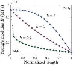
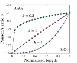
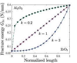
First, fracture in an alumina/zirconia functionally graded plate is investigated. The functionally graded solid is built by varying the volume fractions of alumina Al2O3 and zirconia ZrO2, as given by the homogenization scheme outlined in Section 2. The elastic and fracture properties of Al2O3 and ZrO2 are given in Table 1 (see, e.g., [33]).
| Al2O3 | ZrO2 | |
|---|---|---|
| Young’s modulus, E (GPa) | 380.0 | 210.0 |
| Poisson’s ratio, | 0.26 | 0.31 |
| Fracture toughness, (MPa) | 5.2 | 9.6 |
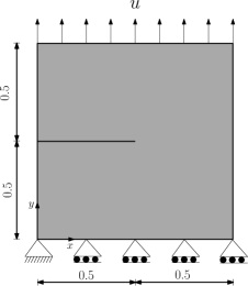
The FGM plate has a mode I edge crack and is subjected to remote uniaxial displacement, see Fig. 1(a). Plane strain conditions are assumed and the variation in space of the critical energy release rate is obtained by using the rule of mixtures and Eq. (9). Different volume fraction profiles are considered, as given by selected values of the volume fraction exponent . The variation of , and along the material gradation direction is shown in Fig. 1 as a function of the material gradient index . The phase field model inherent length scale equals = 0.003 mm; throughout the work, the element size is chosen to be at least 5 times smaller than , so as to resolve the fracture process zone. The model contains a total of approximately 300000 degrees of freedom.
The influence of mode-mixity due to material gradients is investigated through four scenarios, with material properties varying: (1) along the -axis, perpendicular to the crack; (2) along the -axis, with the crack placed in the ZrO2 edge; (3) along the -axis, with the crack placed in the Al2O3 edge; and, (4) with an inclination of 45∘ degrees relative to the crack. The finite element results obtained are shown in Fig. 2(b).
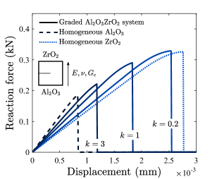
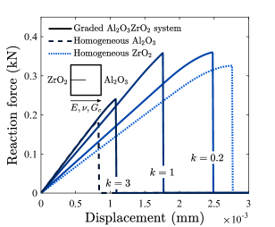
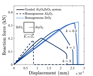
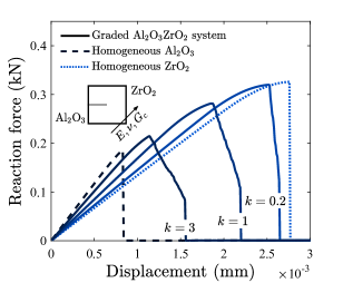
Consider first the results obtained for a material property gradient perpendicular to the crack, see Fig. 2(a). As expected, see Table 1, alumina exhibits a stiffer response than zirconia but an earlier fracture. In the functionally graded cases, the elastic and fracture properties are constant along and the material gradient brings crack tip mode mixity. As inferred from Fig. 1, the material along the crack path will have a larger value of with increasing but a smaller . The force versus displacement response is consistent, with the curves showing an increased stiffness with increasing but a smaller fracture resistance. When the material gradient is parallel to the crack, Figs. 2(b) and 2(c), the response differs drastically depending on where the crack is placed. In all cases the FGM results render a stiffness slope and a maximum force that lie between the ones obtained from the homogeneous samples. In addition, the same qualitative response is observed when increasing ; as in Fig. 2(a), the stiffness increases but failure occurs at a lower load level. However, the response after crack initiation is very different. When the crack propagates from the zirconia-rich side to the alumina-rich side, the value of decreases along the crack path and a sharp drop in the load-displacement curve is observed, see Fig. 2(b). On the other hand, when the initial crack lies in the alumina-rich side, Fig. 2(c), the FGM specimen exhibits an increased resistance to crack propagation. The crack progressively propagates into material with an increasing and the remote displacement required to cause complete breakage can duplicate the displacement attained at the peak load. This enhanced resistance to crack growth persists when the material gradient is not aligned with the crack flank, as observed in the results of Fig. 2(d). It is therefore shown that FGMs can be tailored to gain toughness resistance and prevent unstable fracture, even in the case of brittle ceramic-based FGMs.
3.2 Mixed mode fracture of a graded photodegradable copolymer
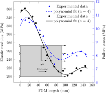
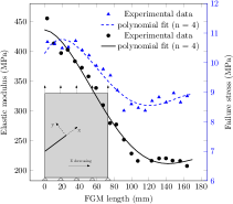
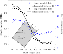
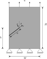
We assess the capabilities of the modelling framework in capturing mixed-mode crack propagation in FGMs. While it is widely considered that the phase field fracture method holds great promise in dealing with crack propagation under mixed-mode conditions, even in homogeneous material comparisons with experiments are scarce [34]. Here, model predictions are benchmarked against the experimental measurements by Abanto-Bueno and Lambros [35] on polyethylene cocarbon monoxide (ECO) exposed to selective UV irradiation. ECO undergoes accelerated mechanical degradation when exposed to UV light so that a sample with continuous in-plane property gradation can be obtained by gradually irradiating a sheet of the material. The material gradation profile is characterized, in terms of Young’s modulus and failure stress , by cutting small strips that are then subjected to uniaxial tension testing. As shown in Fig. 3, we choose to fit the experimental data points with a fourth order polynomial to define the variation of and . The variation of the critical energy release rate is calculated from the measurements by making use of the stress intensity factor solution , where is the geometry factor. As shown in Fig. 4, the geometry under consideration is an edge cracked plate subjected to uniaxial tension. Three different configurations are considered so as to explore the three characteristic geometries of mixed-mode fracture in FGMs; crack tip mixity can be attained either by placing the crack at an angle to the direction of material property variation, or by asymmetric external loading (as in the homogeneous case), or by a combination of both. The effect of each of these cases is here investigated using three specimens respectively labeled FGM I, II, and III. The geometry and dimensions of the specimens are shown in Table 2 and Figs. 3 and 4, along with the data for the reference homogeneous case. In all cases Poisson’s ratio is taken to be constant throughout the specimen and equal to , in agreement with the experimental measurements, see [35] and references therein. In the homogeneous case, the material properties read MPa and J/m2. The phase field length scale is taken to be equal to 0.7 mm. After a mesh sensitivity study, 191735 linear triangular elements are employed to discretize the geometry.
| H | W | h | a | ||
|---|---|---|---|---|---|
| Homogeneous | 90 | 70 | 45 | 33 | |
| FGM I | 75 | 70 | 37.5 | 30 | |
| FGM II | 90 | 70 | 32 | 26 | |
| FGM III | 90 | 70 | 32 | 25 |
The finite element results obtained are shown in Table 3 and Fig. 5(d), along with the experimental measurements by Abanto-Bueno and Lambros [35]. Initial crack kinking angle predictions are in very close agreement with the experimental measurements (Table 3). The phase field method predictions exhibit a better correlation with the experiments than other criteria, such as the so-called maximum tangential stress (MTS) or the generalized maximum tangential stress (GMTS), see [36].
| Crack initiation angles, (deg) | ||
|---|---|---|
| Experiment | Numerical model | |
| Homogeneous | -28 1.5 | -30.4 |
| FGM I | -0 1.5 | 1.4 |
| FGM II | -28 1.5 | -29.9 |
| FGM III | -26 1.5 | -27.6 |
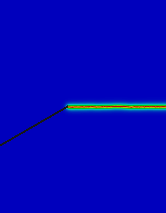
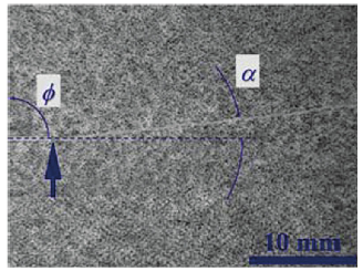
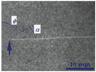
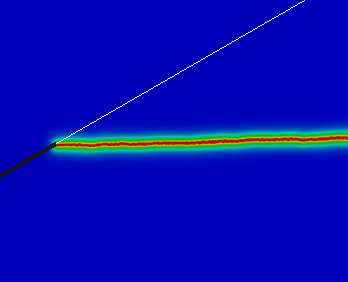
The resulting crack propagation paths are shown in Fig. 5(d). Again, a good agreement with the experiments is observed. In the case where the crack is perpendicular to the material gradient, FGM I - Figs. 5(a) and 5(b), the crack deviates from the natural trajectory of the first mode of fracture and propagates towards the more compliant part of the specimen, where the fracture resistance is also diminishing. For the case FGMII, numerical predictions capture the initial crack kink due to crack tip mode mixity, and the crack then propagates following the distinctive path inherent to the first mode of fracture (see Figs. 5(c) and 5(d)). In FGM III the crack tip axisymmetric stress field induces crack deflection, which is further exacerbated by the spatial gradient. The numerical result qualitatively captures this trend, see Figs. 5(e) and 5(f).

3.3 Failure of compositionally graded glass-filled epoxy specimens
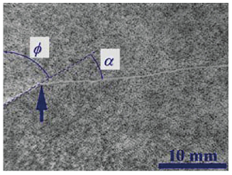
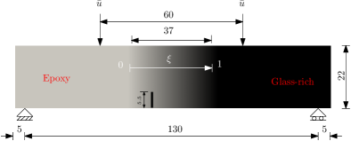
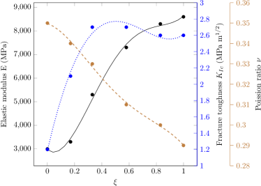
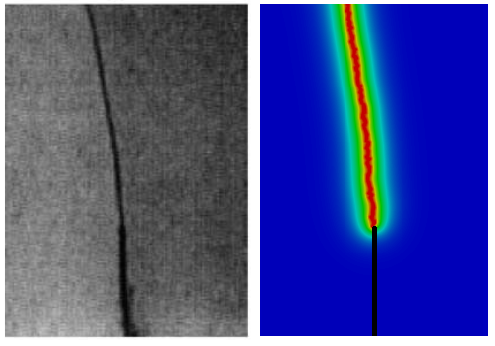
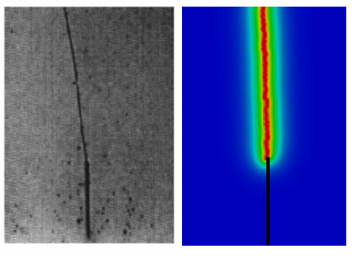
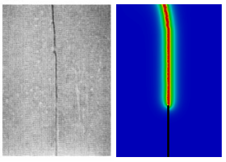
We further assess the capabilities of the model in predicting experimental results by capturing crack growth in graded glass-filled epoxy specimens. We aim at addressing a wide range of FGMs by benchmarking with samples resulting from different manufacturing and characterization techniques. Phase field predictions are compared with the four point bending experiments by Rousseau and Tippur [37]. As shown in Fig. 6(a), material properties change gradually from the epoxy side to the glass-rich side. The length of the graded domain is normalized by , which goes from 0, 100% epoxy, to 1, 100% glass. Three tests are conducted, with the crack being placed at different locations: . The elastic property variation is measured by using ultrasonic pulse-echo measurements; the material property gradient is shown in Fig. 6(b). The length scale equals mm and the variation of is obtained from the fracture toughness measurements. The finite element model reproduces the experimental setup, and a total of 90917 triangular elements are employed.
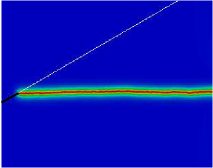
The crack propagation paths predicted are shown in Fig. 7 along with their experimental counterparts for each initial crack location. A very good agreement with the experiments is observed. As the crack location moves towards the epoxy-rich side, crack deflection is enhanced. The crack propagates into the more compliant part, as this results in a greater release of elastic energy. Furthermore, the fracture resistance reduces with diminishing , contributing further to the deviation of the crack path trajectory from the conventional mode I path.
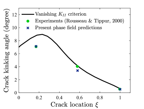
The initial crack deflections, or crack kinking angles, are shown in Fig. 8. We compare our phase field predictions with the experimental measurements by Rousseau and Tippur [37] and with the semi-analytical solution given by the vanishing criterion. As shown in Fig. 8, a very good agreement with the experimental measurements is attained, improving the predictions of the vanishing criterion. The results emphasize the relevance of capturing the spatial variation of to attain accurate predictions; vanishes at the direction of maximum energy release rate.
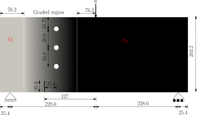
3.4 Complex crack patterns in functionally graded solids
The capabilities of the present phase field formulation for FGMs in predicting complex crack propagation paths are assessed and compared to results from other numerical techniques. We choose to simulate the paradigmatic problem of a cracked beam with three holes, see Fig. 9. The holes are misaligned relative to the initial crack, deviating the crack trajectory from the mode I path. In addition, the material gradient further contributes to the crack trajectory. Material properties vary linearly over the graded region from a domain , with material properties MPa, and MPa, to a domain , with MPa, and MPam. The non-homogeneous beam is subjected to three point bending, as outlined in Fig. 9. The entire specimen is discretized by means of 236253 triangular elements so as to resolve a phase field length scale of = 1 mm along the potential crack path.
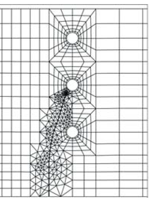
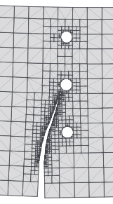
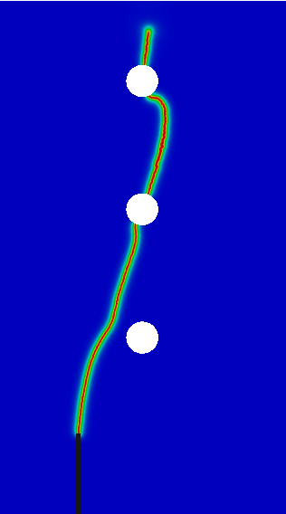
The results obtained, in terms of the crack trajectory, are shown in Fig. 10. The phase field predictions are compared with the results obtained by (a) Kim and Paulino [9], using the maximum energy release rate criterion and a finite element re-meshing algorithm, and (b) Chen et al. [38], with the maximum circumferential stress criterion and the scaled boundary finite element method. A similar crack path is predicted in the three cases; the crack deflects towards the hole region, eventually coalescing with the intermediate hole. The phase field method has the capacity to predict crack nucleation, and consequently the full trajectory until complete separation can be predicted; the crack re-emerges at the top of the intermediate hole, and coalesces with the third hole before reappearing again. Another advantage of the present formulation is the capability of predicting the crack propagation path with the initial mesh. However, if the crack trajectory is uncertain, combining the phase field method with a re-meshing algorithm may prove more computationally efficient.
3.5 3D crack propagation in functionally graded plates
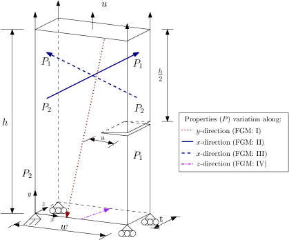
The present modelling framework can also be used to address large-scale engineering problems, as well as to gain insight into the design of three dimensional FGMs with enhanced fracture properties. We demonstrate such capabilities by modelling a plate subjected to uniaxial tension with an edge crack through the thickness, see Fig. 11. Four combinations of crack versus material gradient orientation are considered. We name FGM I the case where the elastic and fracture properties vary gradually along the vertical -axis. In the case of a material gradient along the horizontal axis, we consider two cases (FGM II and FGM III), depending on the location of the crack relative to the compounds. In addition, we consider the case where the material gradient varies along the thickness direction (-axis in Fig. 11); FGM IV. For simplicity, we assume a linear variation of material properties between two cases: material A, with Young’s modulus GPa, critical energy release rate N/mm, and Poisson’s ratio ; and material B, with GPa, N/mm, . A constant length scale is assumed, mm. In FGM II the crack is located on the B-rich edge. A homogeneous case will also be considered, with properties GPa, and N/mm. The specimen, outlined in Fig. 11, has width mm, height mm, thickness mm and initial crack length mm. The finite element model involves 359276 linear tetrahedron elements. Each simulation takes approximately 25 hours running on 2 cores.
Results are shown in Fig. 12 in terms of the force versus displacement response and representative crack paths. As shown in Fig. 12(a), the crack propagates along the extended crack plane in the homogeneous specimen but deviates towards the more compliant side in the graded one, where material properties vary vertically (FGM I). The load-displacement curves exhibits a similar response in both cases, but the graded sample delays fracture due to the local value of and the mode-mixity inherent to FGMs, see Fig. 12(b).
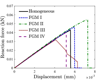
As shown in Fig. 12(b), very different fracture responses can be obtained by placing the material gradient appropriately, relative to the crack surface. For example, in FGM III, where the crack is located on the edge with smaller , cracking initiates early but substantial subcritical crack growth is observed, and final fracture occurs later than in the homogeneous specimen or the graded specimen where properties vary along (FGM I). This is due to the increasing fracture resistance encountered by the crack along the propagation path. On the other hand, FGM II exhibits a significant delay in crack initiation, relative to the other cases, but a sharp drop in the force at the onset of damage. Therefore, the present modelling framework can be employed to quantitatively design FGMs that exhibit a larger time to crack initiation or an enhanced crack growth resistance. In FGM IV, where properties change along the thickness, there is a spatially varying at the crack front. Thus, there will exist a weaker path for crack initiation, relative to the homogeneous case, which will trigger cracking at a lower load, see Fig. 12(b). This is further explored by plotting the phase field parameter contours in Fig. 13. As can be clearly observed, the crack initiates at the edge with smallest , propagates along the and directions, and eventually fractures the specimen.
4 Conclusions
A phase field formulation for fracture in functionally graded materials (FGMs) is presented. The framework has the capability of naturally capturing the gradient in fracture resistance inherent to FGMs via a spatially varying critical energy release rate . A number of paradigmatic examples are addressed to emphasize the potential of the method in modelling the complex crack propagation paths that arise due to crack tip mode-mixity induced by the material property variation. Both two-dimensional and three-dimensional boundary value problems are solved. Unlike previous crack propagation studies on FGMs, the present formulation is proven capable of (i) predicting crack initiation from arbitrary nucleation sites, (ii) capturing crack deflection without re-meshing, and (iii) modelling unstable crack propagation in an implicit framework. The formulation can be readily extended to deal with other related material systems. For example, the extension to metal-based elastic-plastic FGMs is immediate in the absence of plastic-damage coupling, provided that plastic size effects are accounted for [39]. Similarly, the framework can easily accommodate other homogenization schemes, such as those proposed for functionally graded composites integrating carbon nanotubes [40, 41].
In addition, numerical predictions accurately reproduce experiments conducted in different types of functionally graded specimens, and under a wide range of material gradient profiles. The results obtained provide fundamental and quantitative insight into the role of the material property gradation on the crack propagation response. We identify combinations of volume fraction profiles and material gradient orientations that optimize crack growth resistance, laying the grounds for the design of fracture-resistant FGMs. These could be useful, for example, in components exposed to aggressive environments, where cracks and other stress raisers appear at the exposed surface.
5 Acknowledgements
E. Martínez-Pañeda acknowledges financial support from the Royal Commission for the 1851 Exhibition through their Research Fellowship programme (RF496/2018).
References
- [1] J. Aboudi, S. M. Arnold, M. J. Pindera, Response of functionally graded composites to thermal gradients, Composites Engineering 4 (1) (1994) 1–18.
- [2] M.-J. Pindera, J. Aboudi, S. M. Arnold, Thermomechanical Analysis of Functionally Graded Thermal Barrier Coatings with Different Microstructural Scales, Journal of the American Ceramic Society 36 (6) (1998) 1525–1536.
- [3] Y. D. Lee, F. Erdogan, Residual/thermal stresses in FGM and laminated thermal barrier coatings, International Journal of Fracture 69 (2) (1994) 145–165.
- [4] P. Ramaswamy, S. Seetharamu, K. Varma, K. Rao, Al2O3-ZrO2 Composite coatings for thermal-barrier applications, Composites Science and Technology 57 (1997) 81–89.
- [5] M. T. Tilbrook, K. Rozenburg, E. D. Steffler, L. Rutgers, M. Hoffman, Crack propagation paths in layered, graded composites, Composites Part B: Engineering 37 (6) (2006) 490–498.
- [6] M. J. Pindera, J. Aboudi, S. M. Arnold, W. F. Jones, Use of composites in multi-phased and functionally graded materials, Composites Engineering 28 (1-2) (1997) 1–175.
- [7] S. Uemura, The Activities of FGM on New Application, Materials Science Forum 423-425 (2003) 1–10.
- [8] F. Erdogan, Fracture mechanics of functionally graded materials, Composites Engineering 5 (7) (1995) 753–770.
- [9] J.-H. Kim, G. H. Paulino, Simulation of Crack Propagation in Functionally Graded Materials Under Mixed-Mode and Non-Proportional Loading, International Journal of Mechanics and Materials in Design 1 (1) (2004) 63–94.
- [10] C. Comi, S. Mariani, Extended finite element simulation of quasi-brittle fracture in functionally graded materials, Computer Methods in Applied Mechanics and Engineering 196 (41-44) (2007) 4013–4026.
- [11] H. Bayesteh, S. Mohammadi, XFEM fracture analysis of orthotropic functionally graded materials, Composites Part B: Engineering 44 (1) (2013) 8–25.
- [12] E. Martínez-Pañeda, R. Gallego, Numerical analysis of quasi-static fracture in functionally graded materials, International Journal of Mechanics and Materials in Design 11 (4) (2015) 405–424.
- [13] E. Ooi, S. Natarajan, C. Song, F. Tin-Loi, Crack propagation modelling in functionally graded materials using scaled boundary polygons, International Journal of Fracture 192 (1) (2015) 87–105.
- [14] Z. H. Jin, G. H. Paulino, R. H. Dodds, Cohesive fracture modeling of elastic-plastic crack growth in functionally graded materials, Engineering Fracture Mechanics 70 (14) (2003) 1885–1912.
- [15] G. Francfort, J.-J. Marigo, Revisiting brittle fracture as an energy minimization problem, Journal of the Mechanics and Physics of Solids 46 (8) (1998) 1319–1342.
- [16] D. H. Doan, T. Q. Bui, N. D. Duc, K. Fushinobu, Hybrid phase field simulation of dynamic crack propagation in functionally graded glass-filled epoxy, Composites Part B: Engineering 99 (2016) 266–276.
- [17] T. Van Do, D. H. Doan, N. D. Duc, T. Q. Bui, Phase-field thermal buckling analysis for cracked functionally graded composite plates considering neutral surface, Composite Structures 182 (2017) 542–548.
- [18] C. McAuliffe, H. Waisman, A coupled phase field shear band model for ductile-brittle transition in notched plate impacts, Computer Methods in Applied Mechanics and Engineering 305 (2016) 173–195.
- [19] J. Bleyer, R. Alessi, Phase-field modeling of anisotropic brittle fracture including several damage mechanisms, Computer Methods in Applied Mechanics and Engineering 336 (2018) 213–236.
- [20] M. J. Borden, T. J. R. Hughes, C. M. Landis, A. Anvari, I. J. Lee, A phase-field formulation for fracture in ductile materials: Finite deformation balance law derivation, plastic degradation, and stress triaxiality effects, Computer Methods in Applied Mechanics and Engineering 312 (2016) 130–166.
- [21] C. Miehe, F. Aldakheel, A. Raina, Phase field modeling of ductile fracture at finite strains: A variational gradient-extended plasticity-damage theory, International Journal of Plasticity 84 (2016) 1–32.
- [22] J. Reinoso, M. Paggi, C. Linder, Phase field modeling of brittle fracture for enhanced assumed strain shells at large deformations: formulation and finite element implementation, Computational Mechanics 59 (6) (2017) 981–1001.
- [23] V. Carollo, J. Reinoso, M. Paggi, A 3D finite strain model for intralayer and interlayer crack simulation coupling the phase field approach and cohesive zone model, Composite Structures 182 (2017) 636–651.
- [24] F. P. Duda, A. Ciarbonetti, S. Toro, A. E. Huespe, A phase-field model for solute-assisted brittle fracture in elastic-plastic solids, International Journal of Plasticity 102 (2018) 16–40.
- [25] E. Martínez-Pañeda, A. Golahmar, C. F. Niordson, A phase field formulation for hydrogen assisted cracking, Computer Methods in Applied Mechanics and Engineering 342 (2018) 742–761.
- [26] G. Bellettini, A. Coscia, Discrete approximation of a free discontinuity problem, Numerical Functional Analysis and Optimization 15 (3-4) (1994) 201–224.
- [27] N. A. Fleck, J. W. Hutchinson, Z. Suo, Crack path selection in a brittle adhesive layer, International Journal of Solids and Structures 27 (13) (1991) 1683–1703.
- [28] E. Martínez-Pañeda, On the Finite Element Implementation of Functionally Graded Materials, Materials 12 (2019) 287.
- [29] M. Ambati, T. Gerasimov, L. De Lorenzis, A review on phase-field models of brittle fracture and a new fast hybrid formulation, Computational Mechanics 55 (2015) 383–405.
- [30] M. S. Alnaes, J. H. J. Blechta, A. Johansson, B. Kehlet, A. Logg, C. Richardson, J. Ring, M. E. Rognes, G. N. Wells, The FEniCS Project Version 1.5, Archive of Numerical Software 3 (100) (2007) 9–23.
- [31] Hirshikesh, S. Natarajan, R. K. Annabattula, A FEniCS implementation of the phase field method for quasi-static brittle fracture, Frontiers of Structural and Civil Engineering 13 (2) (2019) 1–17.
- [32] Hirshikesh, S. Natarajan, R. K. Annabattula, Modeling crack propagation in variable stiffness composite laminates using the phase field method, Composite Structures 209 (2019) 424–433.
- [33] H. Hadraba, K. Maca, J. Cihlar, Electrophoretic deposition of alumina and zirconia: II. Two-component systems, Ceramics International 30 (6) (2004) 853–863.
- [34] K. H. Pham, K. Ravi-Chandar, C. M. Landis, Experimental validation of a phase-field model for fracture, International Journal of Fracture 205 (1) (2017) 83–101.
- [35] J. Abanto-Bueno, J. Lambros, An experimental study of mixed mode crack initiation and growth in functionally graded materials, Experimental Mechanics 46 (2) (2006) 179–196.
- [36] A. Oral, J. Lambros, G. Anlas, Crack Initiation in Functionally Graded Materials Under Mixed Mode Loading: Experiments and Simulations, Journal of Applied Mechanics 75 (5) (2008) 051110.
- [37] C. E. Rousseau, H. V. Tippur, Compositionally graded materials with cracks normal to the elastic gradient, Acta Materialia 48 (16) (2000) 4021–4033.
- [38] X. Chen, T. Luo, E. T. Ooi, E. H. Ooi, C. Song, A quadtree-polygon-based scaled boundary finite element method for crack propagation modeling in functionally graded materials, Theoretical and Applied Fracture Mechanics 94 (2018) 120–133.
- [39] T. V. Mathew, S. Natarajan, E. Martínez-Pañeda, Size effects in elastic-plastic functionally graded materials, Composite Structures 204 (2018) 43–51.
- [40] J. Reinoso, A. Blázquez, Geometrically nonlinear analysis of functionally graded power-based and carbon nanotubes reinforced composites using a fully integrated solid shell element, Composite Structures 152 (2016) 277–294.
- [41] A. Frikha, S. Zghal, F. Dammak, Finite rotation three and four nodes shell elements for functionally graded carbon nanotubes-reinforced thin composite shells analysis, Computer Methods in Applied Mechanics and Engineering 329 (2018) 289–311.