Magnetic field generation from a coil-shaped foil by a laser-triggered hot-electron current
Abstract
A strong electron current triggered by a femtosecond relativistically intense laser pulse in a foil coil-like target is shown to be able to generate a solenoidal-type extremely strong magnetic field. The magnetic field lifetime sufficiently exceeds the laser pulse duration and is defined mainly by the target properties. The process of the magnetic field generation was studied with 3D PIC simulations. It is demonstrated that the pulse and the target parameters allow controlling the field strength and duration. The scheme studied is of great importance for laser-based magnetization technologies.
-
December 2018
1 Introduction
Optical approaches are known to provide efficient and robust sources of extremely high magnetic fields in a laser laboratory. One of the main mechanisms responsible for quasistatic magnetic field production in such schemes is the discharge currents in a specially shaped conducting material, for example, metal wires [1, 2, 3]. But with very intense relativistic laser pulses, an additional effect comes from the current of accelerated electrons [4]. The laser-accelerated electrons leaving a target form a direct current, which generates a strong azimuthal magnetic field around it. If the laser pulse is very short, then the discharge process occurs as a propagating discharge wave [5]; a shaping of the discharge conductor can result in a sophisticated time-dependent field structure [6]. Such optically generated magnetic fields are very interesting for radiation and particle acceleration, particle guiding, and a wide range of other magnetized plasma studies.
Here, we present a scheme that under certain conditions utilizes both the current of the laser-accelerated electrons and the discharge current. In our case with a single-turn foil loop, they form a closed current contour similarly to what the discharge current does in capacitor-coil schemes [1, 2]. The scheme can be easily adjusted to control the magnetic field properties by changing the target geometry and the laser parameters. Using a very compact geometry compared to capacitor-coil targets [1, 2], for example, allows using very short laser pulses to confine the generated propagating discharge electromagnetic wave. Along with large petawatt laser facilities, this allows applying this scheme with table-top femtosecond lasers.
2 PIC simulation of magnetic field generation.
The 3D simulation of magnetic field generation by a shot laser pulse was performed with the PIC code Mandor. A laser pulse of 0.5 J energy has a Gaussian shape in time (30 fs FWHM duration) and space (4 m FWHM focal spot size). These parameters correspond to a maximum pulse intensity W/cm2, which gives a dimensionless linearly polarized laser field amplitude (for the laser wavelength m). We used two type of targets (see Fig. 1) consisting of electrons with density of , where is critical density, and heavy immovable ions. The simulations were collisionless and were performed with spatial grid steps of in a simulation box . In all the cases, the laser pulse was focused at the front side of the target surface in a hot spot with the center point coordinates .
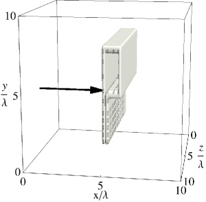
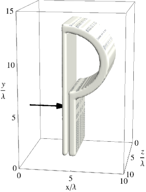
The less time-consuming simulation with the first target design was used simply to demonstrate the basic principle of magnetic field generation, and the second allows increasing the volume of the strong magnetic field, although both target designs are basically the same. This design uses the foil emitter–collector setup, where the laser-irradiated flat face part of the foil (emitter) emits hot electrons, which bombard the flat plate (collector) behind. There is a narrow vacuum gap 1 m thick between the plates. The plates are actually parts of a shaped foil with the same thickness making a single-turn loop (see Fig. 1).
The idea is to localize the current of fast electrons by a certain initially defined target shape and to add it to a discharge current excited by the laser charging of the irradiated plate [1]. This superposition increases the efficiency of the scheme over a scheme with only the discharge current. The compact size of the target is consistent with the femtosecond laser pulse duration, although it can also switch the regime of magnetic field generation. In the considered situation, the magnetic field would be a field of an electromagnetic discharge wave [6], not a field of a long quasistatic discharge current [2].
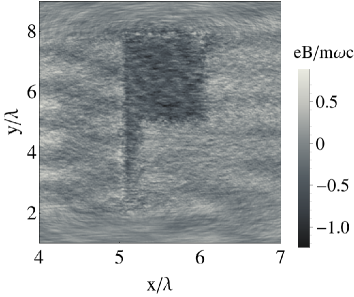
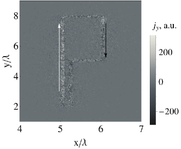
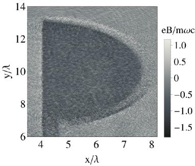
The results of PIC simulations for the first target are shown in Fig. 2. It is clearly seen that a negative magnetic field is generated in the free internal volume of the loop (see the left panel in Fig. 2). This field is due to positive components of electron current on the left target side and its negative component on the right target side, which is also seen in the right panel in Fig. 2.
The electron current corresponds to electrons moving toward the interaction volume. This current is formed by the evacuation of hot electrons under the action of the short laser pulse. To increase magnetic field volume, we passed to the second target type, which also demonstrates formation of a strong magnetic field (see Fig. 3).
We also studied how the magnetic field generation depends on the laser pulse duration. We increased the laser pulse duration from 30 fs to 120 fs and to 300 fs while keeping laser energy constant (the laser intensity respectively decreases four times and one order of magnitude). The magnetic field evolution inside the target in the three cases is shown in Fig. 4.
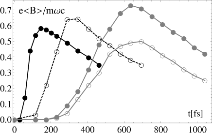
It is clear that despite the laser intensity decrease, an increase of the laser pulse duration results in an increase of the magnetic field amplitude. In all the cases, the magnetic field amplitude reaches a maximum value after the laser pulse terminates, i.e., the magnetic field growth times are indeed equal to the laser pulse time duration. There is then a slower decrease of the magnetic field average values with approximately the same characteristic decay time of the order of 1.25 ps. The maximum value of the magnetic field is of the order of 7 kT and can be achieved for the 300 fs laser pulse duration. We note that using long laser pulses (with duration 300 fs) results in some nonuniformity of the generated magnetic field component inside the target loop. It has a maximum near the foil center and drops to the target boundary (cf. two gray lines in Fig. 4 ).
3 Discussion
In this section, we present a simple qualitative analysis of the numerical results, to increase their clarity and to relate them to a more realistic situation of metal targets rather than the plasma model target used in the numerical simulations. The magnetic field production and evolution can be estimated by replacing the specifically shaped target (see Fig. 1) with a series circuit of a capacitor and inductor (cf. [2]). Such a representation is valid for a quasistatic field if its characteristic wavelength is much greater than the target size [7]. For the driven target, two limit situations can be distinguished depending on the ratio of the laser pulse duration to the time of the electromagnetic pulse propagation along the target perimeter at the speed of light . For , the discharge once excited propagates as a wave in the target. The process is strongly nonstationary and should be considered based on the full set of Maxwell equations with the displacement current and corresponding dielectric permittivity. In the opposite situation, , the discharge driven by the laser provides a quasistationary electron current source that allows a simpler estimate for the magnetic field. The PIC simulations are applicable in both regimes.
For the used target geometry, the contour length is m, which corresponds to the time fs, and the 30 fs FWHM laser pulse hence corresponds to the parameter . An increase of the pulse duration to 120 fs yields . Below, we use the quasistatic approach to estimate the characteristic values, but we note that for a more accurate description, the electromagnetic problem must be considered. The oscillatory structure in Figs. 2 and 3 demonstrates the role of the wave processes for the parameters of interest.
The magnetic field generation process under irradiation of the target by an intense relativistic laser pulse is governed predominantly by the target properties, such as its geometric shape and the dielectric permittivity. First, we consider the gap between the emitter and collector plates at the bottom of the target in Fig. 1. When the laser pulse irradiates the emitter, electrons are accelerated inside the gap forward to the collector, creating a charge density and a potential difference (electrostatic sheath) inside the inter-plate gap. The formed sheath potential keeps most of the ejected electrons at a distance of the order of the Debye length, which is less than the gap thickness. For a laser field amplitude , the ponderomotive electron energy scaling [8] gives an effective electron temperature MeV. Assuming that of the laser energy is deposited in the hot electrons (see, e.g., [9]), we can estimate their number as , i.e., electrons. Distributing all these electrons over the volume given by the Debye sheath thickness and a hot spot with a radius of the order of m, we can estimate the ejected electron density as cm-3, which results in a Debye length of m. The positive potential of the emitter created during laser irradiation of the target drives a replacement (discharge) electrical current. This replacement current structure propagates from the irradiated emitter along the target surface as a high-frequency discharge wave and on the time scale of reaches the collector to create a strong positive potential there. At this instant, it disrupts the locking sheath potential, an acceleration potential appears in the gap, the laser-heated electrons start to accelerate toward the collector, and short circuit occurs. After that, the electrical current enters the quasistatic regime. If the laser pulse lasts considerably longer than , almost all laser-generated hot electrons are not locked by the sheath potential and participate directly in the quasistatic current.
The magnetic field strength in a quasistationary situation can be estimated as , where is the characteristic scale of the target radius. Using the above estimate of the number of hot electrons, we can calculate the maximum possible current kA. This electrical current is able to produce a magnetic field at the level of kT. But in the case of a short pulse, the quasistationary condition is not completely satisfied, and the second plate cannot accept all the current instantaneously. The efficiency of the magnetic field generation therefore seems low. For a longer pulse, the quasistatic situation allows electrons to form a steady circuit, and the resulting magnetic field seems closer to the above estimate. The numerical difference in these estimates can appear from estimation uncertainties in the target geometry, electron energies, absorption efficiency, and other factors.
The magnetic field strength, its growth rate duration, and the efficiency of generation demonstrated above reasonably correspond to the PIC simulations with the collisionless plasma model target. After excitation, the magnetic field relaxes. Because the simulations are collisionless, there is no ohmic resistance in a plasma target, and magnetic field decay with the time scale of about 1 ps shown in Fig. 4 can differ from that in a real experiment with a metal foil with a finite conductivity. The magnetic field decay (Fig. 4) is likely to be due to electromagnetic wave emission from the target loop by a nonstationary electrical current. We note that sharp kinks on the curved foil also contribute to such emissions as enhanced localized sources of high-frequency energy leakage. The amplitudes of the emission fields are small compared with the generated magnetic field strength. Therefore, the characteristic decay time of the magnetic field is longer than its growth rate duration. Some indication of the emission mechanism is provided by the oscillatory structure in Fig. 3.
In the case of a metal foil coil target, the magnetic field relaxation can be qualitatively described by the solution of the equivalent LR circuit equation
where is the source voltage, is the target resistance, is the electrical current in the target, and is its inductance. The relaxation time is defined by and . The target inductance estimated in SI units is pH. For the resistance calculation, a correct target cross section where electrical current can flow should be taken into account. This cross section is defined by the target skin depth in the high-frequency domain. Correspondingly, it increases for the longer relaxation time scale. The resistivity in copper is about s-1 in CGS units or m and usually increases with temperature [11]. On a time scale of 30 fs, the surface target layer corresponding to where a current propagates would be of the order of or less than one tenth of a micron. Then , where mm and ps. We can therefore expect the magnetic field decay to be several times slower than what is seen in the PIC simulations. For more realistic calculations, the frequency and temperature dependence of the resistivity should be carefully analyzed. We note that these estimates applicable in the quasistatic limit are similar to those for capacitor-coil targets [12], although the target geometry and all characteristic times and lengths are quite different.
4 Conclusion
We have presented a new, rather simple scheme for generating ultra-strong magnetic fields in specially designed targets under the action of ultrashort intense table-top laser pulses. The performed 3D PIC simulations predict the generation of a quasistationary magnetic field with a maximum amplitude up to 7 kT in a volume of about 100 m3 generated by a 500 mJ femtosecond laser pulse, which is quite a strong field for such a moderate laser energy. We studied the time evolution of the generated magnetic fields. The qualitative estimates show that the time duration of the magnetic field generated using a metal foil with finite conductivity would be at least at the ten picosecond time scale, much longer than the driving laser pulse.
Acknowledgments
This work was supported by the Russian Foundation for Basic Research (Grant No. 18-02-00452-a). Numerical simulations were partially performed at the Joint Supercomputer Center of the Russian Academy of Sciences and with resources of NRNU MEPhI High-Performance Computing Center.
References
- [1] Korobkin V V and Motylev S L 1979 Soviet Technical Physics Letters (in Russian) 5 474.
- [2] Santos J. J. et al. 2018 Physics of Plasmas 25 056705.
- [3] Korneev P, Tikhonchuk V and D’Humières E 2017 New Journal of Physics 19 033023.
- [4] Korneev P, D’Humières E and Tikhonchuk V 2015 Physical Review E 91 43107.
- [5] Quinn K et al. 2009 Physical Review Letters 102 194801.
- [6] Kar S et al. 2016 Nature Communications 7 10792.
- [7] Landau L D et al. 2013 Electrodynamics of Continuous Media Course of Theoretical Physics (Elsevier Science).
- [8] Wilks S C, Kruer W L, Tabak M, and Langdon A B 1992 Physical Review Letters 69 1383.
- [9] Roth M and Schollmeier M 2016 CERN Yellow Reports 1 231.
- [10] Chen S. N. et al. 2014 Physics of Plasmas 21, 023119.
- [11] Zaghloul M R 2008 Physics of Plasmas 15 042705.
- [12] Tikhonchuk V T, Bailly-Grandvaux V, Santos J J, and Poyé A 2017 Physical Review E 96 023202.
- [13] Daido H. et al. 1986 Phys. Rev. Lett. 56 846.
- [14] Fujioka S. et al. 2013 Sci. Rep. 3 1170.
- [15] Zhu B. J. et al. 2015 Appl. Phys. Lett. 107 261903.
- [16] Zhang Zh. et al. 2018 High Power Laser Science and Engineering 6 e38.
- [17] Liao G. et al. 2016 Matter and Radiation at Extremes 1 187.