On the performance limits of coatings for gravitational wave detectors made of alternating layers of two materials
Abstract
The coating design for mirrors used in interferometric detectors of gravitational waves currently consists of stacks of two alternating dielectric materials with different refractive indexes. In order to explore the performance limits of such coatings, we have formulated and solved the design problem as a multiobjective optimization problem consisting in the minimization of both coating transmittance and thermal noise. An algorithm of global optimization (Borg MOEA) has been used without any a priori assumption on the number and thicknesses of the layers in the coating. The algorithm yields to a Pareto tradeoff boundary exhibiting a continuous, decreasing and non convex (bump-like) profile, bounded from below by an exponential curve which can be written in explicit closed form in the transmittance-noise plane. The lower bound curve has the same expression of the relation between transmittance and noise for the quarter wavelength design where the noise coefficient of the high refractive index material assumes a smaller equivalent value. An application of this result allowing to reduce the computational burden of the search procedure is reported and discussed.
keywords:
Dielectric multilayers, Gravitational Wave Interferometric Detectors, Multiobjective optimizationDOI: 10.1016/j.optmat.2019.109269
1 Introduction
The first direct detection of gravitational waves (henceforth GW) by the LIGO [1] and Virgo [2] detectors, and the recent Multi Messenger observation of GW170817 - GRB 170817A - SSS17a/AT 2017gfo marked the birth of Multi Messenger Astronomy (MMA) [3, 4]. Increasing the visibility distance of the operating GW detectors is a needed step to deploy the full potential of MMA. Thermal (Brownian) fluctuations in the high-reflectance (HR) coatings of the test-masses is presently the dominant noise source in interferometric GW detectors [5] setting their ultimate visibility distance in the (40-300) Hz band, where all recent detections have been made. Notably, efforts to reach and beat the quantum noise limit will be meaningful only after a significant reduction of coating thermal noise is achieved.
Reducing coating thermal noise is thus the top current priority in GW detectors R&D [6]. The current research direction in coating technology explore two promising options for reducing coating thermal noise as needed by new generation detectors, namely the search of new material (e.g. crystalline materials [7] nm-layered composite materials [8], Silicon Nitrides [9, 10] etc.), and the optimization of coating design, and deposition parameters to achieve the best relevant figures of merit (low optical and mechanical losses, high optical contrast).
In this paper we focus on optimization of the coating structure adopted in advanced LIGO and advanced Virgo. High reflectance test-mass coatings consist of multilayers of alternating low and high refractive index materials (silica and 14.5% titania-doped tantala in the advanced LIGO and Virgo [11, 12]), which must provide the required reflectance with minimal thermal noise [13].
High reflectance optical coatings typically consist of a stack of identical high/low index layer pairs or doublets, where each layer is quarter wave thick at the operating frequency [11]. This design features the minimum number of layers to achieve some specified reflectance, but does not yield the minimum noise among all possible iso-reflective designs (see [13] chapter 12).
An alternative design consisting of a stack of identical doublets (with the exception of the terminal top/bottom doublets) with non-quarter wave layers was proposed in [14, 15] and further explored in [16], and shown to outperform the classical quarter wavelength design.
In this paper, we formulate for the first time to the best of our knowledge a multiobjective coating optimization problem consisting in the minimization of both coating transmittance and thermal noise. We use a global optimization method (Borg MOEA [17]), making no a priori assumptions about layer thicknesses, and we find a simple closed form lower bound of the general coating performance in the transmittance-noise plane. Also, the end-tweaked stacked-doublet coating structure of the optimized coatings assumed in [13, 14, 15] on the basis of partial evidences, is obtained in a rigorous way.
In the following an dependence on time is implicit, where is the angular frequency and is the imaginary unit.
The paper is organized as follows: in Sect. 2 and 3 we introduce the optical and thermal-noise model. Constrained optimization and the multiobjective formulation are discussed in Sect. 4. The results are collected in Sect. 5, conclusions and recommendations for future research follow in Sect. 6.
2 Coating optical modeling
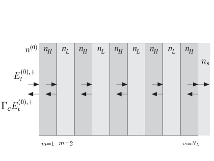
Let us consider a coating consisting of a multilayer placed between two homogeneous dielectric half-spaces with refractive indexes and , respectively (see Fig. 1). The rightmost half-space (with refractive index ) is the substrate, while the leftmost one is the vacuum. Let a monochromatic plane wave impinge normally on the coating from the vacuum. The optical reflections and transmission properties of a multilayer structure can be computed in a closed form using the characteristic matrix method [18, 19].
The characteristic matrix of the th layer can be written [20]:
| (1) |
where
| (2) |
and are the free space wavelength and the layer thickness, respectively, and is the complex refractive index
| (3) |
where is the extinction coefficient111 In view of the assumed dependence on the time , absorbing media have ..
The optical response of the whole coating can be computed from the multilayer characteristic matrix,
| (4) |
where is the total number of layers numbered from the vacuum to the substrate as illustrated in Fig. 1.
The complex reflection coefficient at the vacuum/coating interface is given by:
| (5) |
where is the effective refractive index of the whole multilayer structure,
| (6) |
The power transmittance at the vacuum/coating interface is .
The average power density dissipated within the coating can be computed as the difference between the average power density flowing into the coating at the first interface (vacuum/coating) and the power density flowing into the substrate (last interface ) . The input power is
| (7) |
where is the incident transverse electrical field at the vacuum/coating interface and is the characteristic impedance of the vacuum. The power density flowing into the substrate is given by using the definition of Poynting vector as follow
| (8) |
where and are total transverse electric and magnetic fields at the last interface. The complex amplitude and are obtained from and using the formula
| (9) |
3 The thermal noise model
The power spectral density of coating thermal noise is given, under suitable simplifying assumptions, by [13]
| (10) |
where is the frequency, is the (absolute) temperature, is the(assumed Gaussian) laser-beam waist, and and are the Poisson and Young modulus of the substrate, and the coating loss angle is
| (11) |
where
| (12) |
and being the mechanical loss angle and the Young’s modulus of the th layer, respectively.
According to eq (10), increasing the beam-width and lowering the temperature result in a reduction of coating noise [13]. Using wider (e.g., higher order Gauss-Laguerre) beams is another option, also being currently investigated [21]. Decreasing works for coating materials that does not exhibit mechanical loss peaks at the (cryo) temperatures of interest [22]. Current research is accordingly focused on finding (synthetizing and optimizing) better materials featuring low optical absorption and scattering losses, low mechanical losses down to cryo temperatures, and high optical contrast (allowing fewer layers to achieve a prescribed transmittance, resulting into thinner coatings and lower noise). In this paper we focus on reducing the coating loss angle by optimizing the layer thicknesses.
4 Coating optimization
In this section we focus on the optimization of the coating structure sketched in Fig. 1. Let us use the suffixes S,L,H to identify substrate (S), low (L) and high (H) index material, respectively. In the following we consider a coating consisting of layers beginning with the high refractive index materials222This is not restrictive, since the used optimization alghorithm is allowed to set the thickness of each and any layer to zero. at the vacuum/coating interface .
As a consequence of the above assumptions
| (13) |
With this assumptions the coating noise angle becomes:
| (14) |
where and . Defining the normalized loss angle and introducing the normalized physical length , where is the free space wavelength, we have:
| (15) |
where the noise ratio coefficient can be explicitly written as:
| (16) |
In the case where the refractive index is the same as that of the substrate material (as in current GW detectors) is taken as an odd number333In fact choosing an even results in a configuration with the rightmost layer made of low refractive index material which increases the noise without any effect on the reflectivity..
4.1 Constrained optimization formulation
The optimization of the mirrors for GW detectors is a peculiar problem. In standard mirror optimization design it is important to achieve high reflectance in a given frequency and angular range. In the case of mirrors for GW detectors, the incidence is normal and the frequency range is very narrow (laser signal at ) but it is mandatory to find a mirror setup that induces the minimal additional (thermal) noise on the detection channel. Therefore it is important, in a suitable sense, to reduce both the power transmittance and the thermal noise loss angle .
As a consequence, a straightforward formulation of the coating optimization problem for the design of low noise dielectric mirror can consist in searching for the thickness sequence that minimizes the thermal noise keeping the transmittance below a prescribed threshold value . This is a typical constrained optimization problem [23] that in mathematical notation can be written :
| (17) | ||||||
| subject to |
where the constraint transmittance should be typically a few part per million (henceforth ppm).
Note that, in view of the transmittance constraint, problem (17) is non-linear and non-convex. The search space is defined by the inequalities for odd and for even .
An alternative way to formulate the optimization problem can consist in searching for the thickness sequence that minimizes the transmittance keeping the thermal noise below a given threshold value:
| (18) | ||||||
| subject to |
where is a prescribed maximum allowed loss angle.
4.2 Multiobjective optimization formulation
The optimum coating design problem has been formulated in two alternative ways not necessarily equivalent in eq.s (17) and (18). In this section, we introduce a multiobjective optimization approach [24, 25] where we search for the thickness sequences minimizing simultaneously the transmittance and the loss angle. With a non-standard mathematical notation we write:
| (19) |
Solving problem (19) in the framework of multiobjective optimization means to find its tradeoff curve, also referred as the Pareto front or Pareto boundary, in the plane. Each point belonging to the Pareto front corresponds to a sequence of layer normalized thicknesses.
In order to define the Pareto front of (19) the concept of dominance [24] has to be introduced, to define a suitable ordering rule in the plane. A physically feasible solution in the space dominates another (different) physically feasible solution if the coordinates of are orderly less or equal to those of . The set of physically feasible solutions, for which no physically feasible dominant solution exists, is the Pareto front of the multiobjective optimization problem. Let us note that the problem (17) can be solved using the Pareto front of (19), by choosing the point on the Pareto front with transmittance component equal to . Similar considerations can be done for the problem (18), which can be solved by taking the point on the Pareto front with noise component equal to . Furthermore, the properties and structure of the Pareto front can give some hints on the relationship between problem formulations (17) and (18).
5 Numerical solution of multiobjective optimization problem
Many algorithms, based on different global multiobjective optimization tools, are available in order to face the problem of Pareto front computation for high dimensional problems. These algorithms generally use a suitable sampling method of the physical feasible configuration space, enabling the reconstruction of the Pareto front ( e.g. NSGA-II, NSGA-III, -MOEA etc. see [25]).
In this paper we perform a numerical exploration of the Pareto front (19) using a state of the art, public domain Multi Objective Evolutionary Algorithm (MOEA) named Borg MOEA [17], that uses an evolutionary strategy appropriate for continuous variables. The algorithm is implemented as a package [26] written in the Julia language [27]. The relevant literature and a simple description of the algorithm are reported in Appendix A.
Most multi objective algorithms use mutation, crossover and selection operators, that do not change throughout the execution program. The Borg MOEA uses different operators from existing MOEAs and adopts them adaptively on the basis of their success in the search. The evaluation of the progress, the adaptation of the population size and the increasing of the archive with new solutions help the algorithm to continue the progress and prevents it from being trapped in some loop for the entire runtime. The goodness of numerical solutions given by the Borg MOEA are compared with reference solutions. We consider for comparison with the Borg MOEA optimized design, the coating structure which is currently used in Virgo/LIGO test masses [12], consisting of alternating quarter wavelength layers of SiO2/ Ti-doped Ta2O5 deposited on a fused silica substrate. The physical parameters used in our simulations are reported in Table 1.
| Coating | Substrate |
| H (amorphous Ti-doped Ta2O5 ) | (bulk crystalline SiO2) |
| L (SiO2) | |
| GPa | |
| GPa | |
| GPa | |
5.1 Pareto front convergence and structure
It is well known that deterministic stopping criteria for global evolutionary optimization algorithms are unavailable. Therefore, in order to investigate the convergence of the used algorithm, we computed the Pareto fronts with for increasing evolution times sec. The numerical estimated maximum absolute deviations (i.e. the uniform norm distance between Pareto curves at and ) are reported in Table 2 showing that the Pareto fronts do not change significantly for sec.
| Evolution Time [sec] | Absolute Error |
|---|---|
As a consequence, we took (ad abundantiam) sec in our simulations.
In Fig. 2(a) we display Pareto fronts for the cases , i.e. ranging from to with step . It is seen that the Pareto fronts exhibit several bumps, whose number is equal to the number of high refractive index material layers.
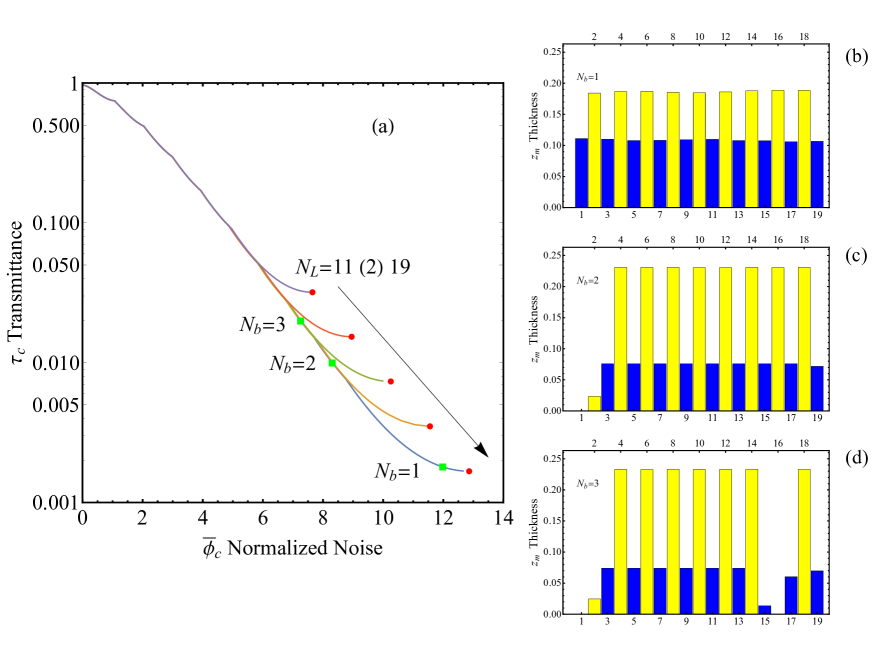
The bumps are less visible in the lower transmittance region. In Fig. 2 (b),(c),(d) the sequences of layer thicknesses corresponding to the square green markers in Fig. 2(a) are displayed. It can be noted that the bump with lowest transmittance ( in Fig. 2(b)) corresponds to a mirror configuration with all layer thicknesses different from zero. Moreover, we note that the rightmost red point of the bump corresponds to the quarter wavelength design at the operating wavelength with . This is in agreement with the well known quarter wavelength design property of minimizing transmittance in the cases of multilayer reflectors made of negligibly absorbing materials [28]. The next bump corresponds to a mirror design where the thickness of a single layer of high refractive index has been practically set to zero (see Fig. 2(c)). For the case illustrated in Fig. 2(d), the thickness of an additional layer of low index material is set to zero; this implies that the two nearby high refractive index layers merge toghether and can be considered as a single layer. We found that the above behaviour can be generalized to all bumps, i.e. the generic bump fairly corresponds to a multilayer structure with high refractive index layers.
This feature is a general characteristic of the Pareto front of dielectric mirror multiobjective optimization, which are, in summary, continuous, decreasing, and non-convex (bumpy) curves. The continuity of multiobjective tradeoff curves implies that the problems (17) and (18) are mathematically equivalent. In fact if we consider a generic point on the Pareto front, we find that is the solution of problem (17) with constraint , while is the solution of problem (18) with constraint .
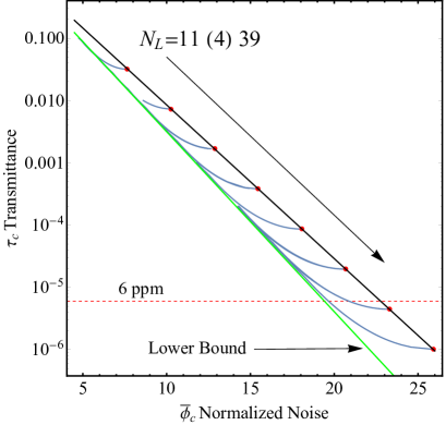
In order to consider design configurations that exhibit performances of potential interest for present GW interferometer detectors, we performed simulations for coating multilayer up to with the physical parameters reported in Table 1. In Fig. 3 we display the Pareto curves (blue lines) for ranging from to with step . The red points in Fig. 3 are the quarter wavelength design which are located on a curve that can be written (under some approximations) as a straight line in the log-linear axes scale of the plane . The equation of the straight line is (see Appendix B for details):
| (20) |
The tradeoff curves asymptotically locate near to a straight line (green line in Fig. 3) in the plane with a log-linear axes scale. The equation of this line turns out to be the same eq. (20) where the noise ratio coefficient is reduced to an effective value , computed by regression of Pareto front data. We conjecture that this curve is a lower bound for all tradeoff curves in the region of low transmittance () above the Koppelmann limit [29], that is placed at for the parameters reported in Table 1. The Koppelmann limit is also the order of magnitude of normalized energy absorption (assorbance) in the sought design in Fig. 2(b)(c)(d) and in the following.
The horizontal dashed red line ppm shown in Fig. 3 corresponds to the target transmittance required for the design of dielectric mirrors used in GW detectors. The quarter wavelength coating with is the reference design because it matches the target transmittance with the lowest normalized noise.
It is clear that each tradeoff curve with contains layer configurations satisfying the constraint ppm and showing a reduced normalized noise with respect to the quarter wavelength reference design.
In figure 4(a)(b)(c) the layer thickness configurations obtained by the intersections between tradeoff curves with and the horizontal transmittance line ppm are displayed. These configurations give a reduction of the normalized noise with the respect to the quarter wavelength reference design of about respectively. Note that the designs reported in Fig. 4(a) and 4(b) belong to the first bump of the tradeoff curves respectively, while the configuration in Fig. 4(c) belongs to the second bump of the Pareto front .
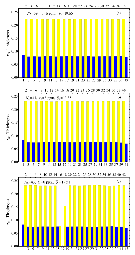
Moreover, let us note that the thickness sequences look like a truncated periodic configuration except for the first two layers and the last one. The normalized physical length of the internal layers with high and low refractive index materials are and , respectively, corresponding to normalized optical lengths and , whose sum is less than .
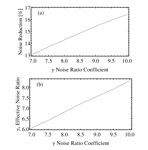
In view of the uncertainty in the measurements of the specific loss angle coefficient, we have performed all the above simulations considering the same refractive indexes , and (see Table 1) and changing the noise ratio coefficient in the range . All of the above findings are confirmed. We report in Fig. 5 a summary of the relevant results. In particular, the noise reduction of the optimized coating structure with respect to the reference quarter wavelength design and the effective noise ratio coefficient are reported as functions of in Fig. 5(a) and 5(b), respectively. We have shown that both the noise reduction (gain) and the effective noise ratio are almost linear, increasing functions of the noise ratio coefficient .
The above parametric exploration has been done exploiting the possibility in reducing the computational burden for the calculation of the limiting curve of Pareto fronts. Indeed the bound given by eq. (20) can be evaluated only for two value of in a moderately low region, and than extrapolated via mono-parametric regression to the whole low transmittance region above the Koppelman limit.
| Parameters | |||||
|---|---|---|---|---|---|
| Periodic | Tweaked | Borg MOEA | |||
|
|
9.1214 | 9.1054 | 9.1054 | ||
|
|
16.5918 | 16.5879 | 16.5879 | ||
|
|
19.5968 | 19.5809 | 19.5809 |
5.2 The tweaked periodic solution and the mixture checks
We have found that the thickness sequences look like a truncated periodic configuration with the exception of the two topmost layers and the last one. This result corroborates the working hypothesis used in previous papers [14, 15]. As a further check, we have implemented a code to face the tweaked periodic truncated design problem where the search space is reduced to a five-dimensional space by setting , and for the first two layers and the last one in the dielectric mirror. In the remaining layers for all odd in the range we set , and for all even in the range we set . In Table 3 we report the tweaked and the complete multiobjective solutions. We note that in terms of noise reduction an agreement on the first four decimal figures is found. We have also considered the periodic truncated design with a two-dimensional search space . The results shown in Table 3 evidentiate a deviation of the periodic truncated design with respect to the full evolutionary solution. This difference in the tradeoff curve increases in the low transmittance region.
A final check has been carried out in order to verify whether it is convenient to substitute the high refractive index material (noisier material) with a layered mixture of this material and the low index one. To this end we expand the search space including for the high refractive layers (modeled like a mixture with layered inclusion) an additional variable which account for the percent of high refractive index material present in the layered mixture. In the case of layered inclusion the mixture refractive index can be modeled following [30, 31] and is , while the normalized thermal noise ratio becomes . The multiobjective simulations performed in the expanded -dimensional space , using the same parameters of Table 1 and for different values of , shown that the Pareto tradeoff curve does not change because the algorithm automatically finds that . This result implies that mirror design made of true (i.e. with ) layered mixture solutions are located above the binary coating Pareto fronts.
The failure of this check definitively gives an answer on the optimality of mirror design with subwavelength layered inclusions in the case of coatings made of two materials, and also establish that it is not convenient to arbitrarily increase , keeping fixed , to search the optimal solutions.
6 Conclusions
In this article we faced the problem of optimizing the design of binary (two-materials) coatings for GW detectors by formulating and solving a multiobjective optimization problem. This approach allowed us to minimize both the transmittance and the thermal noise. While the values of the refractive indexes and the number of the layers are given, no a priori hypothesis on the thickness of the layers was made in the multiobjective optimization problem, tackled using a global optimization method (Borg MOEA) in a search space with a dimension equal to the number of layers.
We have shown by extensive numerical simulation based on Borg MOEA algorithm the existence of a Pareto tradeoff boundary which is a continuous, decreasing, and non-convex (bump-like) curve. In particular, continuity implies that the multiobjective approach (19) is equivalent to the constrained single-objective optimization problems (17) and (18). A solution (i.e. a mirror design) on the Pareto front corresponds to a sequence of layer thicknesses.
The thicknesses sequences on the Pareto boundary look like truncated periodic configurations except for the first two layers and the last one. In view of this result (see also [14]), we faced the optimization problem in a search space with a reduced dimension. We have considered the adapted periodic (five-dimensional search space) and the truncated periodic (two-dimensional search space) sequence. The performance of the tweaked (adapted) periodic sequences are comparable to the performance of the sequences obtained by the solution of the full multiobjective problem. The periodic design is outperfomed by the multiobjective design especially in the low trasmissivity region.
We have also shown that the Pareto fronts are bounded from below by an exponential curve in the transmittance-noise plane (20). This curve has the same expression of the approximate relation between transmittance and noise for the quarter wavelength design, except for the noise ratio coefficient which assumes a reduced effective value. A possible application of eq. (20), consisting in the reduction of the computational burden for the calculation of the Pareto fronts, has been implemented for a parametric exploration in a suitable range.
The noise reduction ( for realisitc cases) has been shown to be (more or less) a linear, increasing function of the noise ratio coefficient .
There is no possibility to ameliorate these performances by using instead of high refractive index material a mixture made of layered inclusions of low refractive index materal, with subwavelength thicknesses, placed inside the high refractive index material.
We are confident that the method used in this paper can be generalized to the analysis of the coating design of dielectric mirror with three or more different materials, to be discussed in a future paper.
Acknowledgments
This work has been partially supported by INFN through the projects Virgo and VirgoET. M. Principe acknowledges the L’Oreal-UNESCO For Women in Science Program for supporting her in this work. The authors are grateful for the discussion and suggestions received from the Virgo Coating R&D Group and the Optics Working Group of the LIGO Scientific Collaboration.
Appendix A - evolutionary algorithm in a nutshell
The evolutionary algorithms are smart versions of random search derived from the genetic evolution theory and implemented on digital computers. They are well established classical tools for global optimization techniques [32].
To solve optimization problems with an evolutionary algorithm the individuals of a population are associated, by the encoding procedure, to a physical solution of a given problem (in our case the layer thicknesses sequence), the selection probability is proportional to the quality of the represented solution, i.e. to the fitness function to be optimized.
The population then undergoes selection crossover and mutation (like in natural genetics evolution), producing new children and updating the population. The process is repeated over various generations until a suitable termination criteria is reached. Each individual, encoding a candidate solution, is assigned a fitness value , based on its objective function value, and the fitter individuals are given a higher chance to mate and yield more fitter individuals.
The multi objective version of evolutionary algorithm follows the same schema (see [24, 25] for details), with the addition of a suitable strategy of Pareto front extraction.
An evolutionary heuristic follows this basic scheme:
Appendix B - transmittance vs thermal noise for the quarter wavelength design
In this appendix we compute the transmittance as a function of thermal noise for a quarter wavelength coating. The reflectivity of a quarter wavelength multilayer made of alternating layers with high and low refractive indexes and , respectively, placed on a substrate with refractive index is:
| (21) |
where . In view of eq. (21) the transmittance reads:
| (22) |
that can be written as
| (23) |
For , by applying the on both side of the equation (23) we get
| (24) |
On the other hand, specializing eq. (15) for the quarter wavelength design, the normalized loss angle can be written as a function of
| (25) |
Solving (25) for and plugging into (24) we have:
| (26) |
References
References
- [1] website http://www.ligo.caltech.edu
- [2] website http://www.virgo.infn.it
- [3] B.P. Abbott, et al., Multi-messenger Observations of a Binary Neutron Star Merger, Ap. J. Lett. 848 (2017) L12.
- [4] M. Branchesi, Multi-messenger astronomy: gravitational waves, neutrinos, photons, and cosmic rays, J. Phys. Conf. Ser. 718 (2016) 022004.
- [5] M. R. Abernathy, X. Liu, T. H. Metcalf, An overview of research into low internal friction optical coatings by the gravitational wave detection community, Materials Research 21 (2018) e20170864 .
- [6] R. Flaminio, J. Franc, C. Michel, N. Morgado, L. Pinard, B. Sassolas, A study of coating mechanical and optical losses in view of reducing mirror thermal noise in gravitational wave detectors, Class. Quantum Grav. 27 (2010) 084030.
- [7] G.D. Cole, W. Zhang, B. J. Bjork, D. Follman, P. Heu, C. Deutsch, L. Sonderhouse, J. Robinson, C. Franz, A. Alexandrovski, M. Notcutt, O. H. Heckl, J. Ye, M. Aspelmeyer, High-performance near- and mid-infrared crystalline coatings, Optica 3 (2016) 647-656.
- [8] H.-W. Pan, S.-J. Wang, L.-. Kuo, S. Chao, M. Principe, I. M. Pinto, R. DeSalvo, Thickness-dependent crystallization on thermal anneal for titania/silica nm-layer composites deposited by ion beam sputter method, Optics Expr. 22 (2014) 29847-29854.
- [9] H.-W. Pan, L.-C. Kuo, S.-Y. Huang, M.-Y. Wu, Y.-H. Juang, C.-W. Lee, H.-C. Chen, T. T. Wen, S. Chao, Silicon nitride films fabricated by a plasma-enhanced chemical vapor deposition method for coatings of the laser interferometer gravitational wave detector, Phs. Rev. D 97 (2018) 022004.
- [10] J. Steinlechner, C. Krüger, I. W. Martin, A. Bell, J. Hough, H. Kaufer, S. Rowan, R. Schnabel, S. Steinlechner, Optical absorption of silicon nitride membranes at 1064 nm and at 1550 nm, Phys. Rev. D 96 (2017) 022007.
- [11] L. Pinard, B. Sassolas, R. Flaminio, D. Forest, A. Lacoudre, C. Michel, J. L. Montorio, N. Morgado, Toward a new generation of low-loss mirrors for the advanced gravitational waves interferometers, Optics Letters 36 (2011) 1407-1409.
- [12] L. Pinard, C. Michel, B. Sassolas, L. Balzarini, J. Degallaix , V. Dolique, R. Flaminio, D. Forest, M. Granata, B. Lagrange, N. Straniero, J. Teillon, G. Cagnoli, Mirrors used in the LIGO interferometers for first detection of gravitational waves, Applied Optics 56 (2017) C11-C15.
- [13] G. Harry, T. P. Bodiya, R. DeSalvo, Optical coatings and thermal noise in precision measurements, Cambridge University Press, 2012.
- [14] J. Agresti, G. Castaldi, R. DeSalvo, V. Galdi, V. Pierro, I. M. Pinto, Optimized multilayer dielectric mirror coatings for gravitational wave interferometers, Proc. of SPIE 6286 (2006) 628608.
- [15] A.E. Villar, E. D. Black, R. DeSalvo, K. G. Libbrecht, C. Michel, N. Morgado, L. Pinard, I. M. Pinto, V. Pierro, V. Galdi, M. Principe, I. Taurasi, Measurement of thermal noise in multilayer coatings with optimized layer thickness, Phys. Rev. D 81 (2010) 122001.
- [16] N. M. Kondratiev, A. G. Gurkovsky, M. L. Gorodetsky, Thermal noise and coating optimization in multilayer dielectric mirrors, Phys. Rev. D 84 (2011) 022001.
- [17] D. Hadka , P.M. Reed , Borg: An Auto-Adaptive Many-Objective Evolutionary Computing Framework, Evolutionary Computation 21 (2013) 231-259.
- [18] F. Abelès, La théorie générale des couches minces, Le Journal de Physique et le Radium, 11 (1950) 307-310.
- [19] M. Born , E. Wolf , Principles of Optics: Electromagnetic Theory of Propagation, Interference and Diffraction of Light., Cambridge University Press 1997.
- [20] S. J. Orfanidis , Electromagnetic Waves and Antennas, available as web book https://www.ece.rutgers.edu/~orfanidi/ewa/.
- [21] A. Allocca, A. Gatto, M. Tacca, R. A. Day, M. Barsuglia, G. Pillant, C. Buy, C., G. Vajente, Higher-order Laguerre-Gauss interferometry for gravitational-wave detectors with in situ mirror defects compensation, Phys. Rev. D 92 (2015) 102002.
- [22] I.W. Martin E. Chalkley, R. Nawrodt, H. Armandula, R. Bassiri, C. Comtet, M. M. Fejer, A. Gretarsson, G. Harry, D. Heinert, J. Hough, I. MacLaren, C. Michel, J-L Montorio, N. Morgado, S. Penn, S. Reid, R. Route , S. Rowan, C. Schwarz , P. Seidel , W. Vodel, A. L. Woodcraft, Comparison of the temperature dependence of the mechanical dissipation in thin films of Ta2O5 and Ta2O5 doped with TiO2, Class. Quantum Grav. 26 (2009) 155012.
- [23] A. Antoniou, W. S. Lu, Practical Optimization - Algorithms and Engineering Applications, Springer, Boston, MA, USA 2007.
- [24] M.T.M. Emmerich , A.H. Deutz, A tutorial on multiobjective optimization: fundamentals and evolutionary methods, Natural Computing 17 (2018) 585-609 .
- [25] D. Kalyanmoy, Multi-Objective Optimization Using Evolutionary Algorithms, John Wiley and Sons, Inc. New York, NY, USA 2001.
- [26] R. Feldt, BlackBoxOptim, GitHub repository https://github.com/robertfeldt/BlackBoxOptim.jl (2019).
- [27] website https://julialang.org
- [28] C. K. Carniglia , J. H. Apfel , Maximum reflectance of multilayer dielectric mirrors in the presence of slight absorption, J. Opt. Soc. Am. 70 (1980) 523-534.
- [29] G. Koppelmann, On the theory of multilayers consisiting of weakly absorbing materials and their use as interferometric mirrors, Ann. Phys. 5 (1960) 388-396.
- [30] A. Sihvola, Electromagnetic Mixing Formulas and Applications, The Institution of Engineering and Technology, London, United Kingdom 2008.
- [31] M. Kar , B. S. Verma, A. Basu , R. Bhattacharyya, Modeling of the refractive index and extinction coefficient of binary composite films, Applied Optics 40 (2001) 6301-6306.
- [32] J. H. Holland, Adaptation in Natural and Artificial Systems, University of Michigan Press, 1975.