Experimental Clock Calibration
on a Crystal-Free Mote-on-a-Chip
Abstract
The elimination of the off-chip frequency reference, typically a crystal oscillator, would bring important benefits in terms of size, price and energy efficiency to IEEE802.15.4 compliant radios and systems-on-chip. The stability of on-chip oscillators is orders of magnitude worse than that of a crystal. It is known that as the temperature changes, they can drift more than . This paper presents the result of an extensive experimental study. First, we propose mechanisms for crystal-free radios to be able to track an IEEE802.15.4 join proxy, calibrate the on-chip oscillators and maintain calibration against temperature changes. Then, we implement the resulting algorithms on a crystal-free platform and present the results of an experimental validation. We show that our approach is able to track a crystal-based IEEE802.15.4-compliant join proxy and maintain the requested radio frequency stability of , even when subject to temperature variation of .
Index Terms:
crystal-free radio, IEEE802.15.4, short-range wireless, standard-compliance, clock calibration, reference frequency stability, low-power wireless mesh networking.I Introduction
IEEE802.15.4 [1] is a popular standard for short-range wireless communication. IEEE802.15.4-compliant radios typically operate in the 2.4 GHz frequency band. It is the underlying technology in protocol stacks such as ZigBee or 6TiSCH, which organize a number of IEEE802.15.4-compliant devices in a mesh network topology. These types of networks are widely used in home automation, smart building, smart city and industrial applications.
Manufacturers building IEEE802.15.4-compatible chips must ensure a radio frequency stability not exceeding while transmitting a packet [2]. Crystals are typically used as the reference oscillators for synthesizing the radio frequency, and keeping time. Crystals are popular because they provide the necessary stability while remaining low-power. It is common to use two crystals: a “slow” ultra low-power crystal oscillator for time-keeping (typ. 32,768 Hz) and a “fast” and more power-hungry crystal oscillator for radio frequency synthesis (typ. 12-48 MHz) [3]. Crystal oscillators are, however, off-chip elements. They contribute to the energy consumption, size and cost of the final product, which becomes significant at high volumes (millions of chips) [4].
To further integrate IEEE802.15.4-compliant chips, research is being done on designing on-chip oscillators that could replace the off-chip (crystal) oscillators [5, 6, 7], aiming to obtain crystal-free architectures. Not needing to add crystals to a radio has several key advantages. All elements – including the oscillators – are part of a single piece of silicon. This significantly reduces price of the device. It also reduces its footprint (size) in a design, to the point that it can be used completely standalone, provided it embeds a power source. In the extreme case, such a mote-on-a-chip can even be considered disposable. There are some further benefits, such as the fact that the start-up time of an on-chip resonator is much shorter than that of a crystal, making the system faster to switch on and off. The resulting more efficient duty-cycling further reduces the average power consumption of the crystal-free modules [4].
There are significant challenges to making crystal-free radios. The main advantage of a crystal is that the frequency it oscillates at is very stable over time and temperature, typically in the 10-30 ppm range for regular crystals, even down to 2-3 ppm for temperature- compensated versions [8]. On the other hand, on-chip oscillators suffer from high variations over time and temperature, which we characterize in Section III. These variations would need to be detected and compensated by calibration algorithms running continuously during the lifetime of the crystal-free radio. Efforts have been made towards achieving an on-chip frequency reference of higher accuracy [5, 6, 7], but the temperature influence on these oscillators is still too high for compliance with IEEE802.15.4, as that standard mandates a drift below 40 ppm at all times.
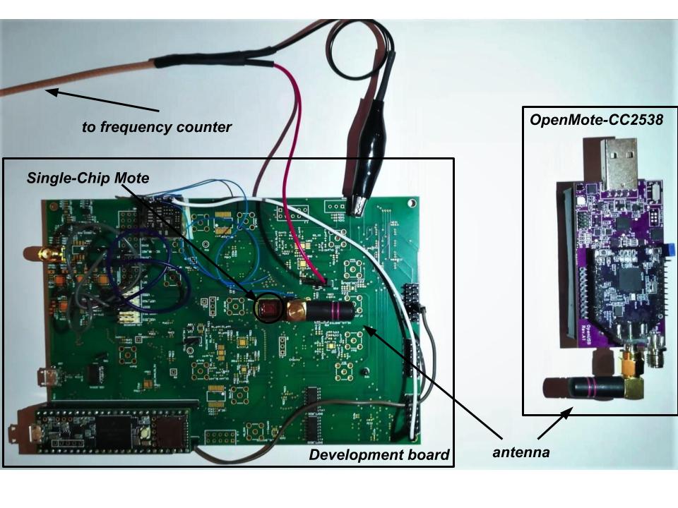
The contribution of this paper is two-fold. First, we develop an method by which a crystal-free platform with an un-calibrated on-chip oscillator tunes its radio to receive IEEE802.15.4-compliant frames, and cope with temperature variations. The resulting algorithm tracks the IEEE802.15.4 frames it receives and continuously fine-tunes the radio to stay within the IEEE802.15.4 oscillator specifications [2] The algorithm is generic and can be applied to any crystal-free platform. Second, we implement and test the algorithm on the “Single-Chip Mote” (SCM) [9], a crystal-free platform that contains a micro-controller and an ultra low-power IEEE802.15.4-compliant radio in a single chip. We evaluate the performance of the solution by having the Single-Chip Mote communicate with an OpenMote [10], a well-known crystal-based IEEE802.15.4 compliant platform. From the best of our knowledge, this paper is the first one to show a crystal-free radio successfully communicating with a crystal-based IEEE802.15.4 compliant radio.
The remainder of this paper is organized as follows. Section II surveys related work on crystal-free radios. Section III characterizes the on-chip oscillators most relevant to this paper. Section IV develops the algorithm for the start-up calibration of the crystal-free radio, and evaluates its performance on SCM. Section V extends the algorithm and the evaluation on maintaining calibration over temperature. Finally, Section VI concludes this paper.
II Related work
Watteyne et al. did some early work with the eZ430-RF2500 platform to replace the “slow” 32 kHz crystal by the internal oscillators of the MSP430 micro-controller on that platform [8]. They implement an adaptive synchronization technique where neighbor nodes re-synchronize to one another at least every 10 s. The resulting drift is approx. 100 ppm. While this work does not attempt to replace the “fast” crystal used by the radio (which is what our paper does), it does show that getting ppm using on-chip oscillators is a challenge.
Mehta et al. explore whether it is possible to relax the requirement IEEE802.15.4 puts on maximum oscillator drift requirements for the RF carrier frequency accuracy from 40 ppm to 1000 ppm [11]. They show, by simulation, that standards-compliant narrow-band wireless communication is still feasible with 1000 ppm oscillators by compensating their drift using a wide bandwidth channel-select filter, a demodulator and an adaptive feedback loop in the receiver.
Wheeler et al. focus on the design parameters and the electronic scheme of a crystal-free radio that has a drift due to phase noise less than the 40 ppm specification of IEEE802.15.4 over 13 h in a constant-temperature environment, and a drift of 95 ppm when the temperature changes [12]. In order to deal with temperature variations, the authors use demodulator-based feedback to allow the receiver to track the drift of the transmitter when the transmitter is placed in a temperature chamber and subjected to a temperature variation of . The devices used in the experiments are composed of FPGA boards and communicate over a wire on which jitter is added to emulate the wireless medium. The receiver is able to track the transmitter’s signal.
Khan et al. propose a solution to calibrate the frequency of a crystal-free radio by tracking the beacons sent by a node that has a crystal reference [13]. This work assumes the crystal-free radio is able to receive the beacons. In order to demonstrate the feasibility of the proposal, the authors use off the shelf OpenMote-CC2538 boards [10]. One OpenMote-CC2538 board is programmed to use its crystal and transmit. The other two OpenMote-CC2538 boards simulate a crystal-free device: RX and RC connected to an FPGA that calibrates the RC oscillator. The authors obtain an accuracy of 70 ppm for a 1 MHz RC oscillator.
Khan et al. extend this work by testing their approach on a FPGA implementation of the digital system of a crystal-free mote [4]. Using a wired setting, the accuracy obtained using network calibration is 47 ppm for a 25 MHz oscillator.
Our paper takes the state of the art one step further, as it presents a complete solution for initially tuning and maintaining the tuning so a crystal-free radio is able to receive a IEEE802.15.4-compliant frame sent by an off-the-shelf crystal-based device. To the best of our knowledge, this is the first paper to achieve this.
III IEEE 802.15.4 crystal-free radio characterization
This section details the challenges is terms of clocking of a crystal-free radio.
For being able to receive and/or transmit IEEE802.15.4 frames, there are two important frequencies that need to be correctly generated by any compliant-device: the radio channel frequency (in the 2.4 GHz band) and the ”chipping” frequency (2 MHz) used to modulate/demodulate the packets. In this paper, we refer to the oscillators generating the radio channel frequency and the 2 MHz frequency as the “RF clock” and the “chipping clock”, respectively. Link-layer level time synchronization between devices that communicate over IEEE802.15.4 are out of scope of this paper, and is a well studied topic [8].
When in receive mode (RX mode), the RF clock is the only one that needs calibration for setting it on the chosen communication channel. This happens because, for RX mode, the chipping clock can be recovered from the incoming IEEE802.15.4 frames by a clock and data recovery module (CDR). When the platform is in transmit mode (TX mode), the on-chip oscillator generating the chipping clock has to be calibrated along with the one generating the RF clock. The system is half duplex: at any given time, the RF clock is used either for transmit, or for receive.
In the remainder of this section, we discuss the stability over time and temperature of the two oscillators that generate the RF clock and TX mode chipping clock, respectively.
III-A Stability over Time
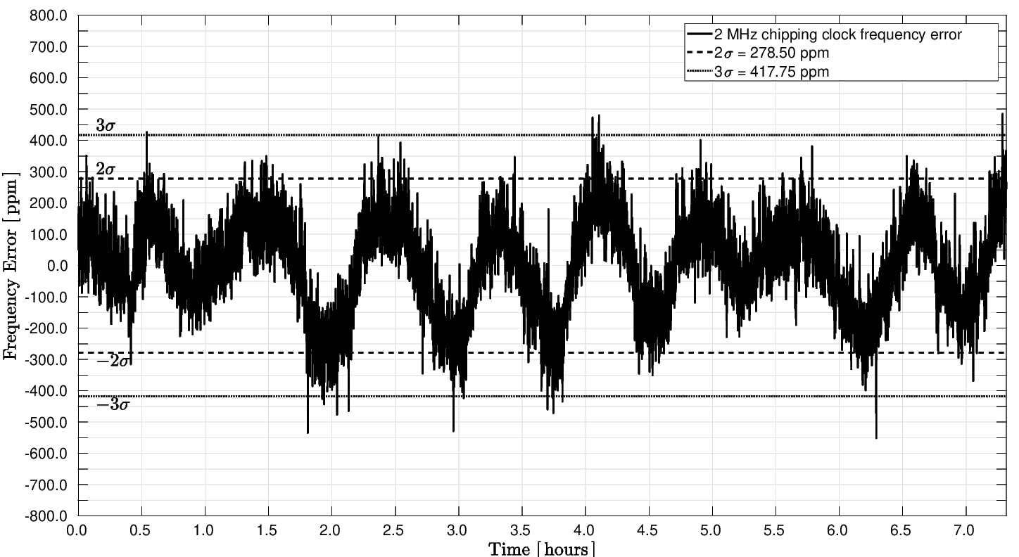
An oscillator drifts over time because of temperature variations and accumulated phase noise. To characterize the stability in time of an oscillator, the external factors that contribute to its drift need to be eliminated (in this case, the temperature variation). Figs. 2a and 2b show the frequency error over a 7 h period of the RF clock and chipping clock, respectively. For obtaining this data, the crystal-free platform was placed in a temperature chamber at constant temperature ( temperature stability) for over 7 h. The output frequency of the two oscillators was measured using the frequency counter capability of the Agilent E4440A spectrum analyzer.
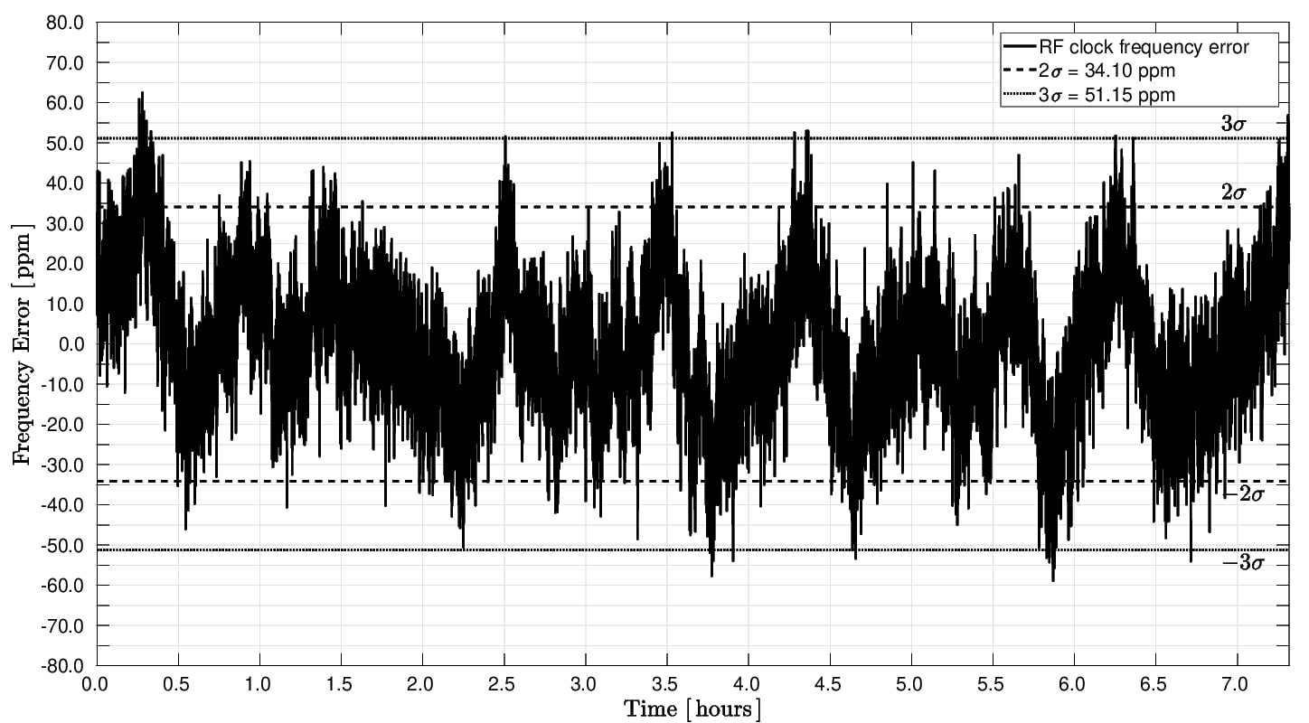
For the RF clock, in roughly 95% of the cases (), the frequency error is within 34.1 ppm. This means that, at constant temperature, this oscillator would meet the IEEE802.15.4 requirements of 40 ppm accuracy. Some samples exceed this (), but these variations can also be a consequence of the fact that the temperature chamber used can only keep the temperature constant with a stability of .
The 2 MHz chipping clock, generated by a different oscillator, drifts mostly within 278.5 ppm (), when at (approximately) constant temperature. This clock has a worse stability than the RF clock, but based on experience and measurements, the tolerable accuracy of this clock for communication can be up to 1000 ppm, which is also documented in [14].
III-B Stability over Temperature
When setting the temperature chamber to vary the temperature from (room temperature) up to , the two clocks experience important drifts. Figs. 3a and 3b show the frequency error of the RF clock and chipping clock, respectively, as the temperature increases over time. The two clocks behave differently. The RF clock frequency decreases in average with , while the chipping clock frequency increases in average with . Deviations from these values could be caused by a slightly different behavior of the oscillators at higher temperatures and/or influenced by the characteristics of the temperature chamber itself ( temperature stability, homogeneity, % temperature set error).
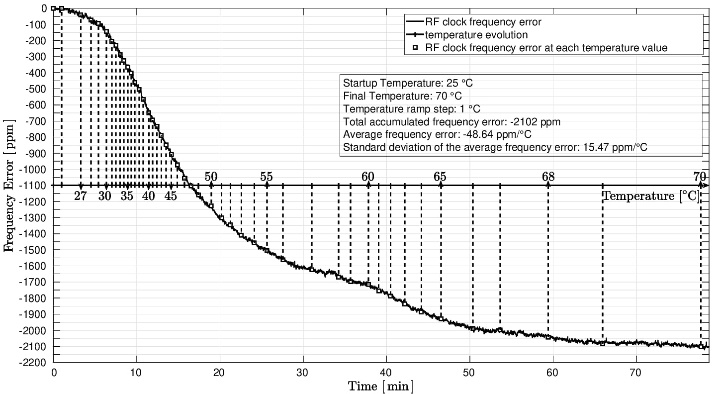
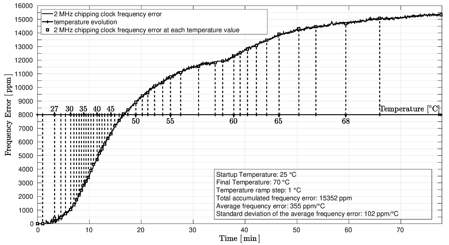
These significant drifts over temperature need to be corrected in order to initiate/maintain communication with an IEEE802.15.4 compliant device.
IV Startup Calibration of a Crystal-free Radio
To establish communication in a TDMA wireless network, an end device listens for a beacon sent by a device already in the network to get the network parameters. It then sends a request to join the network. After the end device and the network mutually authenticate one another, the end device learns about the communication schedule used in the network.
When a crystal-based end device looks for beacons, it can synthesize the beacon channel frequency with a very small error, allowing it to almost immediately receive beacons and process them. This happens because the crystals oscillate at a determined value with a very good stability (10 ppm). For a crystal-free end device, this process is more complicated and time consuming and, as there is no calibrated reference on-chip, at startup, all on-chip oscillators can be for example 10,000 ppm off their nominal value [13]. This section describes the algorithm for tuning to the beacon channel frequency, and the method for calibrating the chipping clock.
IV-A Finding an IEEE802.15.4 Network
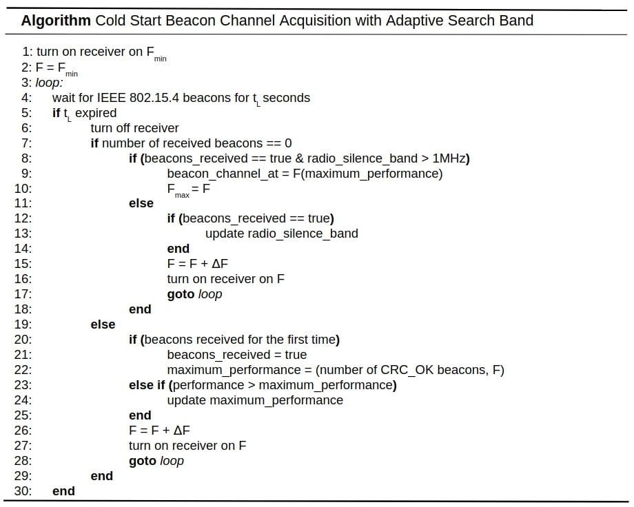
Fig. 4a represents the process of searching for the beacon channel frequency; Fig. 4b represents the corresponding algorithm. The algorithm starts by turning the receiver on (RF clock) and listening for beacons on an unknown frequency, , given by starting the RF clock on the minimum setting it supports in the 2.4 GHz band.
The reason why we qualify as “unknown” is two-fold:
-
1.
Fixing the RF oscillator on the minimum supported setting outputs a frequency that is highly dependent on the temperature in the environment.
-
2.
The resulting value varies highly from RF oscillator to RF oscillator.
We cannot estimate so as to be able to choose a value closer to the (known) beacon channel frequency. Starting the algorithm at makes the algorithm board and temperature independent. The crystal-free mote listens for seconds on this frequency and then updates it to , where is the RF oscillator tuning resolution, obtained by incrementing the oscillator’s minimum supported setting by 1. In our particular case, . The listening duration is chosen so as to be able to receive at least 2 beacons, based on the known interval between beacons (network parameter) and taking into account that the time keeping clocks are crystal-free and uncalibrated too. For these reasons, in our particular case, for , long enough to compensate for an uncalibrated time keeping clock ( 10000 ppm). could be decreased for finding the beacon channel center frequency, , faster.
The algorithm keeps increasing the RF clock frequency in steps, until the radio starts receiving beacons. It then computes the maximum performance parameter and stores the setting of the RF clock at that time. The maximum performance parameter is given by the maximum number of beacons received with a valid CRC OK. This process continues until beacons are not received anymore (radio silence) for more than 1 MHz, to make sure that the beacon channel bandwidth (2 MHz) has been completely scanned. At this point, the algorithm tunes the RF clock on the setting that gave the best performance, as this will be as close as possible to the center frequency of the beacon channel (). The beacon channel does not need to be known in advance. A timeout parameter could be set so as to restart the process in case no beacon could be received correctly.
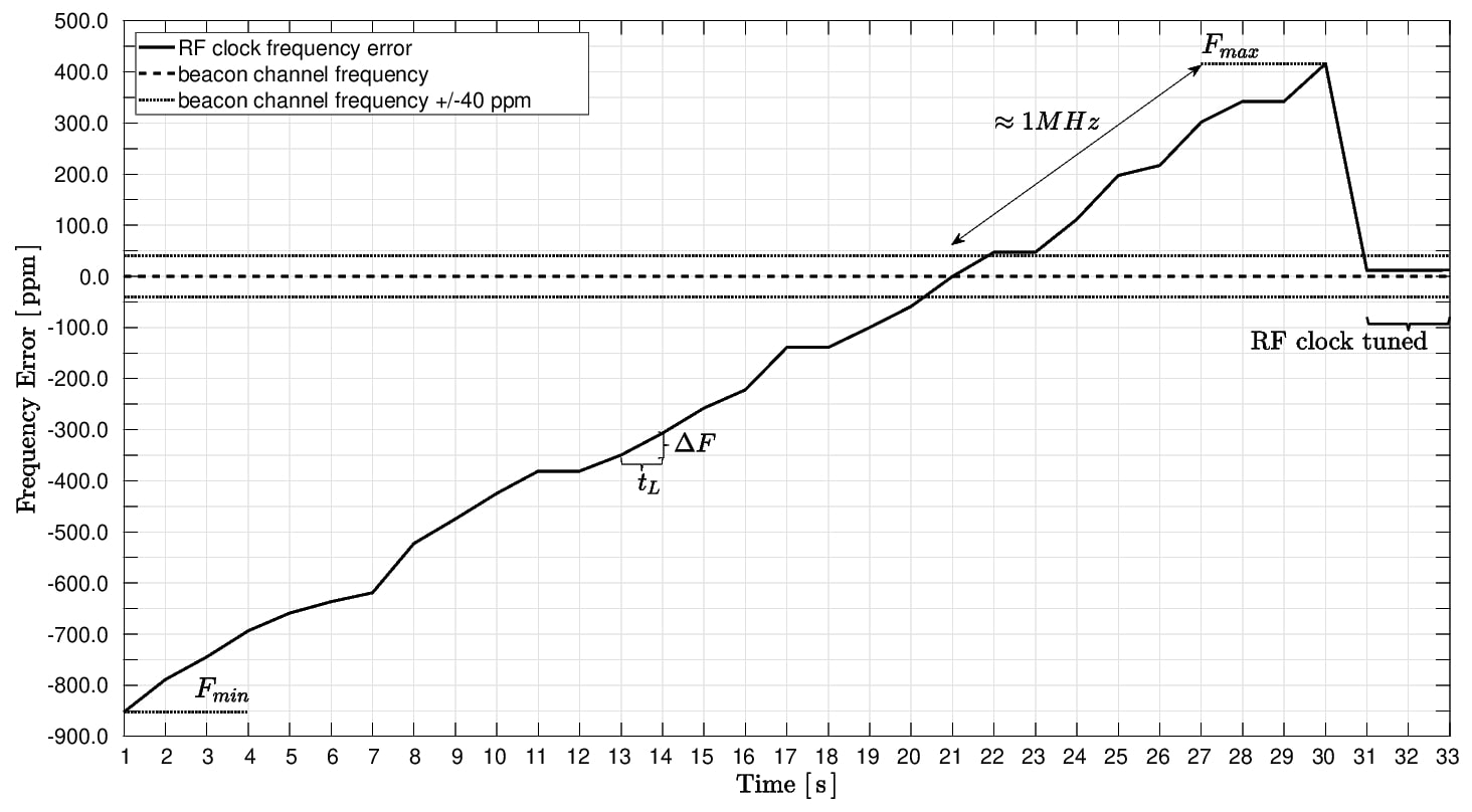
Fig. 5 shows the evolution of the RF clock frequency while running the beacon channel search algorithm on the crystal-free platform, measured with a frequency counter. We can see that, at startup, the RF clock is -850 ppm away from the center frequency of the beacon channel. The RF frequency is increased gradually, and after 1 MHz of radio silence the frequency sweep ends and the RF clock is tuned to the setting that yielded the best performance. The resulting RF frequency is within 40 ppm of the beacon center frequency. Beacons are sent every 125 ms () by an OpenMote and the listening duration () is 1 s.
IV-B Calibrating the Chipping Clock
Once the RF clock is tuned to the center frequency of the beacon, the crystal-free platform can receive the beacons sent every by the OpenMote. To calibrate the chipping clock, one needs to compare the number of ticks between two successive beacons with the value an ideal 2 MHz clock would count, and apply a correction based on its tuning resolution ():
We call this correction “fast calibration,” as it allows one to quickly bring the chipping clock closer to the 2 MHz ideal value. After this is done, more fine corrections can be applied to the chipping clock by adjusting its oscillator setting with 1. These finer corrections can be applied at each received beacon, or after the average number of ticks counted during the last received beacons is compared to a threshold value (a calibration window defining the accepted error of the average counted ticks of ). This latter method is discussed in [4] and proves to have better accuracy than the former.
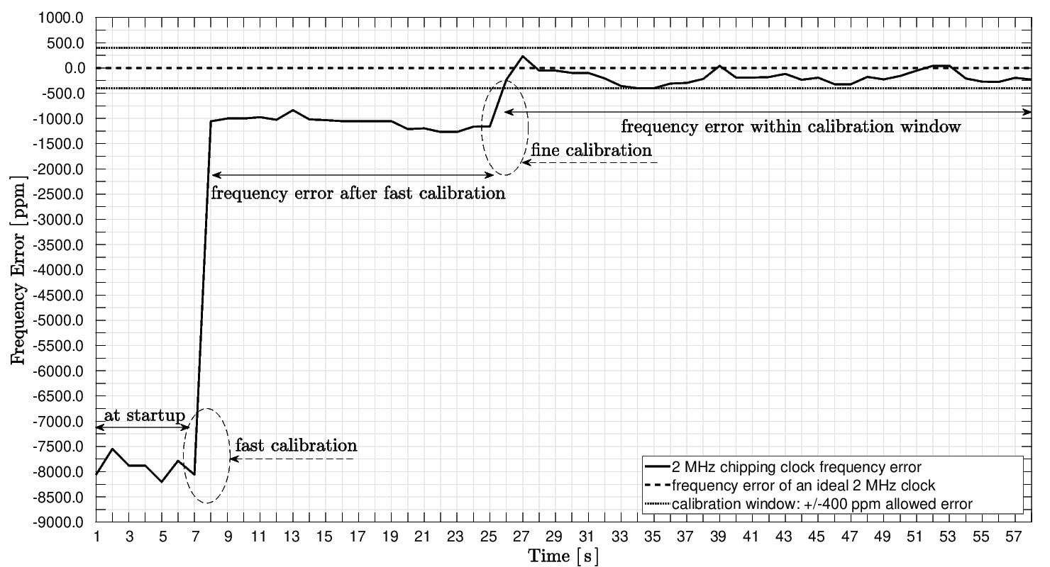
We implement the fast calibration strategy on the crystal-free platform, as well as the fine corrections based on the average number of ticks counted by the chipping clock. We set received beacons before calibration, and a calibration window of accepted frequency error. We extract data with a frequency counter, in laboratory environment. Fig. 6 shows how at startup (while the RF clock looks for the beacon channel), the chipping clock is 8000 ppm away from the nominal 2 MHz value. After fast calibration, it gets within 1000 ppm of the nominal value. After fine calibrations, the chipping clock reaches a frequency error variation inside the defined calibration window. The interval of time between fast calibration and fine calibration is influenced by and by the number of lost beacons: the more beacons are lost, the slower the algorithm reaches the needed packets before the next calibration round.
V Maintaining Calibration over Temperature
The methods presented in Section IV can be applied to calibrate the two clocks of the crystal-free mote at startup, no matter the temperature of the environment. After startup, the frequency errors experienced by the RF and chipping clocks are strongly influenced by temperature variation. This is shown in Fig. 3. This section presents a method for staying calibrated after startup even when the temperature changes.
V-A Correcting the RF clock
As in any standard receive chain, when the RF clock is tuned to the beacon frequency and the crystal-free mote receives a beacon, the received RF signal is down-converted to a specified intermediate frequency (IF) and then demodulated [11]. The IF frequency is a fixed hardware design parameter and can be measured during packet reception. As the temperature in the environment changes, the RF frequency drifts () and the measured IF frequency shows an offset from the expected value, when receiving a packet.
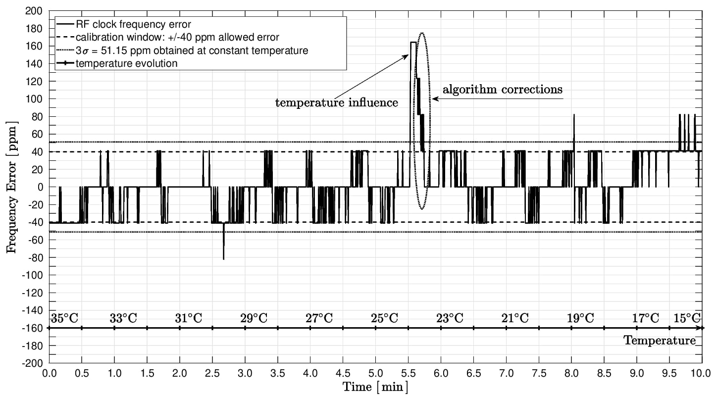
We implement an algorithm that checks the offset of the IF frequency at each beacon reception, and use that to finely tune the RF clock (, depending on the sign of the offset), as this clock is already calibrated on the beacon frequency and only small corrections are needed. This calibration comes at no cost, as the IF information is available at every packet reception. Fig. 7 shows the evolution of the RF clock frequency error while the crystal-free mote is placed inside a temperature chamber and is subject to a temperature change. During this time, the crystal-free platform finely tunes the RF clock based on the measured IF every time a beacon from the OpenMote is received (). The obtained RF frequency error is as good as in constant temperature environment. The frequency error spike in Fig. 7 is a consequence of several lost beacons, but it is corrected as soon as new beacons are received. This is possible because, even if the receiver’s RF clock may have accumulated more than 40 ppm of error, the beacons are still within the bandwidth of the receiver.
The algorithm is packet-loss tolerant, as long as the temperature variation isn’t too large and causes the RF clock to drift outside the communication channel between two packet receptions.
V-B Correcting the Chipping Clock
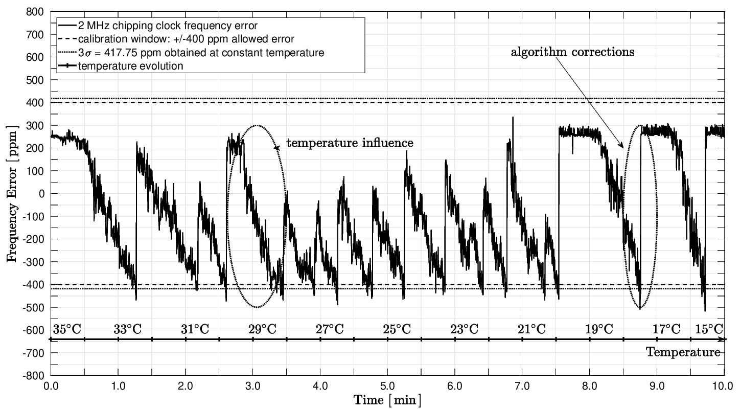
As long as the RF clock is continuously corrected and the crystal-free platform is able to receive beacons against temperature changes in the environment, the 2 MHz chipping clock errors due to temperature can be corrected using the fine calibration method described in Section IV-B.
Fig. 8 shows the performance of the applied fine calibration: the frequency error of the 2 MHz chipping clock is as good as at constant temperature, even when the crystal-free platform is subjected to a temperature variation.
VI Conclusions
In the context of crystal-free radios, this paper analyzes the frequency stability with respect to time and temperature of two fundamental on-chip oscillators. These oscillators drive the wireless communication capabilities of a radio in typical IEEE802.15.4 networks. While the frequency stability in time is good enough to meet the specification demands, these oscillators experience very significant drift over temperature.
We present a mechanism to dynamically compensate that drift to first enable the device to find the appropriate frequency to join the IEEE802.15.4 network, and then to calibrate other on-chip oscillators to support for example chirp decoding. We show that, using the IEEE802.15.4 signaling, we can keep the obtained calibration even as the temperature changes. The obtained accuracy meets the IEEE802.15.4 requirements of frequency stability. All presented strategies are accompanied by experimental results obtained with a crystal-free platform and a crystal-based standards-compliant OpenMote acting as join proxy node of the IEEE802.15.4 network.
Acknowledgment
This work has received funding from the European Union Horizon 2020 research and innovation programme under the Marie Sklodowska-Curie grant agreement No 675891 (SCAVENGE project) and was conducted with the support of the Berkeley Sensor and Actuator Center (BSAC) and the Berkeley Wireless Research Center (BWRC). This work is also partially supported by the Spanish Ministry of Economy and the ERDF regional development fund under SINERGIA project (TEC2015-71303-R).
References
- [1] N. Salman, I. Rasool, and A. H. Kemp, “Overview of the ieee 802.15.4 standards family for low rate wireless personal area networks,” in Symposium on Wireless Communication Systems, Sep. 2010, pp. 701–705.
- [2] Freescale Semiconductor, Inc., “Reference oscillator crystal requirements for mkw40 and mkw30 device series,” https://www.nxp.com/docs/en/application-note/AN5177.pdf, august, 2015, [Online, accessed November 21, 2018].
- [3] D. Griffith, P. T. R⊘ine, T. Kallerud, B. Goodlin, Z. Hughes, and E. T. Yen, “A ±10ppm −40 to 125°c baw-based frequency reference system for crystal-less wireless sensor nodes,” in 2017 IEEE International Symposium on Circuits and Systems (ISCAS), May 2017, pp. 1–4.
- [4] O. Khan, D. Burnett, F. Maksimovic, B. Wheeler, S. Mesri, A. Sundararajan, B. L. Zhou, A. Niknejad, and K. Pister, “Time keeping ability of crystal free radios,” IEEE Internet of Things Journal, pp. 1–1, 2018.
- [5] Y. Shih and B. Otis, “An on-chip tunable frequency generator for crystal-less low-power wban radio,” IEEE Transactions on Circuits and Systems II: Express Briefs, vol. 60, no. 4, pp. 187–191, April 2013.
- [6] X. Zhang, I. Mukhopadhyay, R. Dokania, and A. B. Apsel, “A 46-self-calibrated gigahertz vco for low-power radios,” IEEE Transactions on Circuits and Systems II: Express Briefs, vol. 58, no. 12, pp. 847–851, Dec 2011.
- [7] D. Burnett, B. Wheeler, L. Lee, F. Maksimovic, A. Sundararajan, O. Khan, and K. Pister, “CMOS oscillators to satisfy 802.15.4 and bluetooth LE PHY specifications without a crystal reference,” in 2019 IEEE 9th Annual Computing and Communication Workshop and Conference (CCWC) (IEEE CCWC 2019), Las Vegas NV, USA, Jan. 2019.
- [8] Thomas Watteyne, Branko Kerkez, Kris Pister, Steven Glaser, “Crystal-free network synchronization,” trans. Emerging Tel. Tech. 2016.
- [9] S. Mesri, “Design and user guide for the single chip mote digital system,” Master’s thesis, EECS Department, University of California, Berkeley, May 2016.
- [10] X. Vilajosana, P. Tuset-Peiro, T. Watteyne, and K. Pister, “Openmote: Open-source prototyping platform for the industrial iot,” 09 2015.
- [11] A. M. Mehta and K. S. J. Pister, “Frequency offset compensation for crystal-free 802.15.4 communication,” in The 2011 International Conference on Advanced Technologies for Communications (ATC 2011), Aug 2011, pp. 45–47.
- [12] B. Wheeler, F. Maksimovic, N. Baniasadi, S. Mesri, O. Khan, D. Burnett, A. Niknejad, and K. Pister, “Crystal-free narrow-band radios for low-cost iot,” in 2017 IEEE Radio Frequency Integrated Circuits Symposium (RFIC), June 2017, pp. 228–231.
- [13] O. Khan, B. Wheeler, D. Burnett, F. Maksimovic, S. Mesri, K. Pister, and A. Niknejad, “Frequency reference for crystal free radio,” in 2016 IEEE International Frequency Control Symposium (IFCS), May 2016, pp. 1–2.
- [14] Texas Instruments, “CC2538 powerful wireless microcontroller System-On-Chip for 2.4-GHz IEEE 802.15.4, 6LoWPAN, and ZigBee applications datasheed (Rev. D).”