Numerical study of tearing mode seeding in tokamak X-point plasma
Abstract
A detailed understanding of island seeding is crucial to avoid (N)TMs and their negative consequences like confinement degradation and disruptions. In the present work, we investigate the growth of islands in response to magnetic perturbations. Although we use externally applied perturbations produced by resonant magnetic perturbation (RMP) coils for this study, results are directly transferable to island seeding by other MHD instabilities creating a resonant magnetic field component at the rational surface. Experimental results for island penetration from ASDEX Upgrade are presented extending previous studies. Simulations are based on an ASDEX Upgrade L-mode discharge with low collisionality and active RMP coils. Our numerical studies are performed with the 3D, two fluid, non-linear MHD code JOREK. All three phases of mode seeding observed in the experiment are also seen in the simulations: first a weak response phase characterized by large perpendicular electron flow velocities followed by a fast growth of the magnetic island size accompanied by a reduction of the perpendicular electron velocity, and finally the saturation to a fully formed island state with perpendicular electron velocity close to zero. Thresholds for mode penetration are observed in the plasma rotation as well as in the RMP coil current. A hysteresis of the island size and electron perpendicular velocity is observed between the ramping up and down of the RMP amplitude consistent with an analytically predicted bifurcation. The transition from dominant kink/bending to tearing parity during the penetration is investigated.
pacs:
52.65.Cv, 52.55.Fa, 52.35.-g, 52.65.-yI Introduction
Physics of forced magnetic reconnection in magnetically confined plasmas is crucial to understand magnetic island formation and associated degradation of the plasma confinement and potentially a disruption of the plasma. An instability associated to magnetic reconnection develops in the presence of finite plasma resistivity or other non-ideal effects and is driven by both the equilibrium current density gradient (classical tearing mode) and a ”hole” in the bootstrap current profile (neoclassical tearing mode or NTM) Biskamp (1993); Chang et al. (1998); Smolyakov (1993); Zohm et al. (2001) caused by a flattening of the temperature distribution inside the magnetic island Fitzpatrick (1995).
It was shown both theoretically Drake et al. (1983); Scott et al. (1985); Scott and Hassam (1987); Waelbroeck (1989); Smolyakov (1993); Meshcheriakov et al. (2012) and experimentally Gude et al. (1999); Zohm et al. (2001); Sauter et al. (2002); La Haye (2006); Igochine et al. (2014, 2017) that NTMs are linearly stable and require a seed magnetic island for their growth which is provided by triggers like other MHD instabilities. Resistive MHD predicts tearing modes to be linearly unstable when the parameter , measuring the available magnetic free energy, is positive. Two-fluid pressure gradient effects, the ion polarization current and the toroidal curvature, so-called Glasser-Greene-Johnson effect, provide additional stabilizing effectsAra et al. (1978); Waelbroeck et al. (2001); Glasser et al. (1976).
When a tearing mode is linearly stable, a sufficiently large initial seed island can lead to further island growth since it causes a helical perturbation of the temperature distribution and consequently the bootstrap current, which acts destabilizing. Nonlinear effects and toroidal mode coupling enable the generation of a seed island from an initial perturbation with a different helicity. For example, sawtooth post-cursors with helicity were observed Gude et al. (1999); Igochine et al. (2014) to produce a component acting as seed for a magnetic island.
A basic theoretical framework of tearing mode interactions with a static external magnetic perturbation in cylindrical geometry is proposed by Fitzpatrick Fitzpatrick (1993). In this work, externally applied MPs are treated as modified edge boundary conditions. The interaction of the external MPs with the helical perturbation current associated to a magnetic island results in the modification of the island width evolution and a rise of a local torque in the vicinity of the island. If the island frequency deviates from its natural frequency, the plasma exerts a viscous restoring torque onto the island. The general non-linear tearing mode stability problem is then treated as a balance of the plasma inertia in the island and the sum of the local electromagnetic and viscous torques. In the presence of perpendicular electron velocity, static RMPs in the laboratory frame correspond to time varying RMPs in the electron fluid frame, and therefore induce a current hindering their penetration Nardon et al. (2010); Orain et al. (2013a).
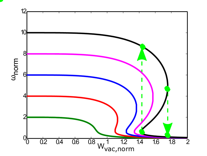
A steady state is obtained when the viscous torque is balanced by the electromagnetic one. Solutions corresponding to different values of initial plasma rotation (and, as a result, island natural frequency) are shown in Fig. 1. For large initial plasma rotation, a bifurcation is observed and the plasma undergoes a sudden transition at about half the initial rotation frequency to a non-linear island state, characterized by low plasma rotation and a large magnetic island. This transition is generally called mode penetration. Due to the bifurcation, a hysteresis is expected for the back transition: The island remains on the lower branch of the figure in the region where the force balance equation does not have a unique solution.
In the present paper, the seeding of a tearing mode by externally applied magnetic perturbations is studied in presence of realistic poloidal and toroidal background rotation. The successive mode evolution and the impact on confinement are also addressed. These questions are investigated with the toroidal nonlinear MHD code JOREK Huysmans and Czarny (2007); Czarny and Huysmans (2008), which includes anisotropic heat transport, two-fluid diamagnetic effectsOrain et al. (2013b), neoclassical friction, and toroidal rotation in realistic tokamak X-point geometry. A discharge in low density L-mode plasmas Fietz et al. (2015a) in the ASDEX Upgrade Kallenbach et al. (2017) tokamak (AUG#30734) was chosen as basis for our studies. Bootstrap current drive is not considered in the present work since we are predominantly interested in the seeding respectively mode penetration, not the further non-linear evolution. Also the effect of neoclassical toroidal viscosity (NTV), which would enhance mode penetration is not taken into account in the present paper. Inclusion of NTV and bootstrap current as well as quantitative comparisons to the experiment are left for future studies.
This paper is organized as follows. In section II, we briefly show experimental observations from ASDEX Upgrade. Section III introduces the JOREK code, the simulation setup, and results of our simulations of mode penetration in ASDEX Upgrade reproducing qualitatively all experimental observations and analytical predictions. This includes observations of penetration thresholds in coil current and background rotation velocity, a hysteresis between ramp-up and ramp-down and a transition from kink- to tearing parity at the resonant surface. Summary and conclusions are given in section IV.
II Mode penetration in ASDEX Upgrade experiments
Experimental results are shown in this section extending previous work described in Ref. Fietz et al. (2015b). Here we refer to the ASDEX Upgrade discharge number . Three distinguished phases were observed in this experiment while the current in the MP field coils with the dominant mode number was slowly ramped up (Figure 2)):
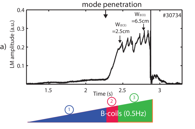
1 In the first phase, denoted weak plasma response phase, the plasma response follows the amplitude of the magnetic perturbation approximately linearly. In this phase, screening is strong and the residual perturbation on the resonant surface is not sufficient to drive magnetic reconnection. In the second phase, the perturbation exceeds a certain threshold and becomes strong enough to slow down the rotation strong enough such that the transition point is reached and forced reconnection takes place at the q=2 surface. The resulting magnetic island is observed in the magnetic data and in the electron temperature. In the third phase, the island growth slows down and is interrupted by some minor disruptions.
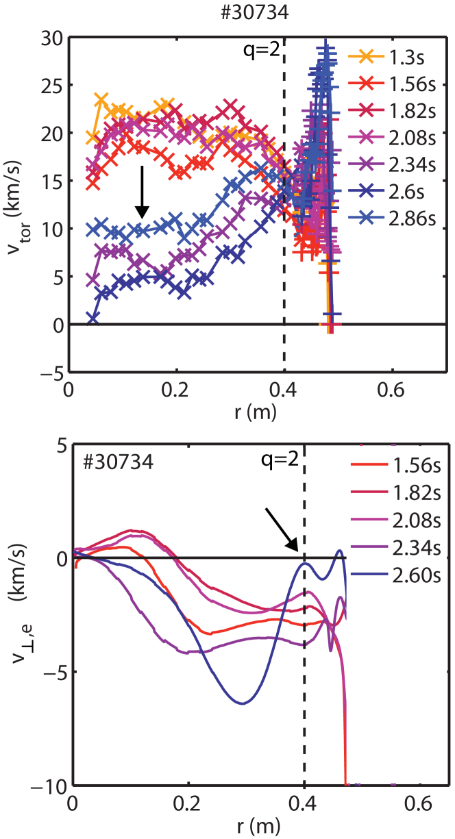
During the first phase (Figure 3), the core toroidal rotation McDermott et al. (2014) decreases up to the point of mode penetration. A fast drop is observed in the second phase and the value remains almost constant during the whole third phase. The perpendicular electron velocity is calculated from the measured ExB velocity and the electron diamagnetic drift velocity. The ExB velocity is evaluated from the Er profile measured with charge exchange recombination spectroscopy via the radial force balance equation, while the electron diamagnetic drift velocity is calculated from the measured electron temperature and density profile. In the plasma core, the toroidal rotation velocity is the dominant term in the radial force balance equation and hence, we have used this term in the radial force balance equation to evaluate the ExB velocity. Further information about the measurements in ASDEX Upgrade is found for instance in Ref. Viezzer et al. (2013). In the first phase, the motion of the electron fluid across the field lines at the resonant surfaces screens the RMPs hindering their penetration in agreement with previous findings that the electron perpendicular rotation is a key factor for the screening of magnetic perturbations by the plasma Waelbroeck (2003); Nardon et al. (2007); Heyn et al. (2008); Orain et al. (2013b). Mode penetration corresponds to a drop of the perpendicular electron velocity to approximately zero. These experiments confirm the predicted slow decrease of the plasma rotation towards the time of mode penetration and the small electron perpendicular velocity when an island is formed. The onset of mode penetration approximately takes place when the perpendicular electron velocity at the rational surface has dropped by a factor of two consistent with analytical predictions.
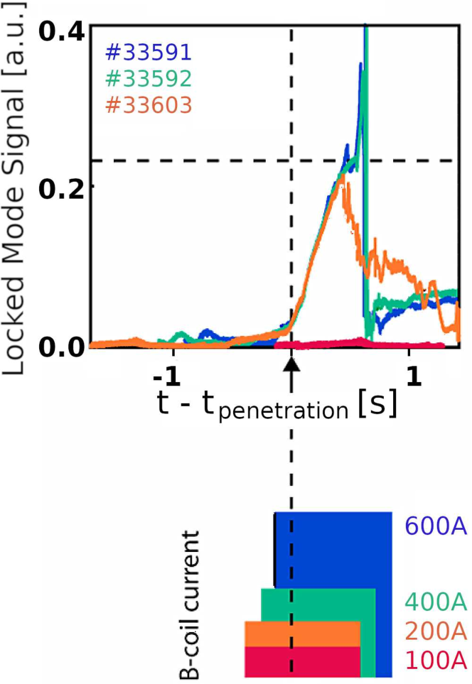
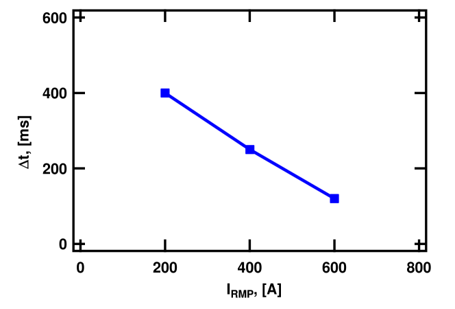
A set of experiments to study the impact of the perturbation amplitude onto mode seeding was performed. The results of these experiments are shown in Fig. 4. The signals of the locked mode detector on the upper part of the plot are shifted in order to match the time of mode penetration across all experiments. The shapes of current amplitude in the RMP coils in the lower part of the Figure are shifted accordingly. The time delay of mode penetration with respect to the RMP ramp-up time increases for lower coil currents, i.e., for lower perturbation amplitudes. Ultimately, when the RMP current becomes too small, no penetration is observed at all. Thus, a threshold in the coil currents is observed for mode penetration (between and in this case), below which the torque does not reduce the perpendicular electron velocity strong enough to reach the transition point.
III Non-linear simulations of mode penetration in ASDEX Upgrade
In the following, we present simulation results for mode penetration by externally applied resonant magnetic perturbations. This section is organized as follows. In Section III.1, the non-linear MHD code JOREK used for the simulations is briefly described and the simulation setup is explained in Section III.2. An overview of all simulations performed is given in Section III.3.
Section III.4 shows results for a simulation of an ASDEX Upgrade like plasma. All three phases of mode penetration can be seen in this simulation consistent with experiments and analytical theory. Also the evolution of toroidal and poloidal rotation is reproduced qualitatively. Section III.5 shows results of parameter scans in mode rotation and the coil currents revealing thresholds for mode penetration in both parameters. A hysteresis in island size and plasma rotation between ramp-up and ramp-down of the magnetic perturbation is observed in Section III.6 consistent with analytical predictions. Finally, Section III.7 investigates the evolution of the kink and tearing responses during mode penetration.
III.1 Physics model and JOREK non-linear MHD code
Our simulations are performed with the 3D non-linear MHD code JOREKHuysmans and Czarny (2007) which is routinely applied to a variety of ELM and disruption related questions in tokamak X-point plasmas and has already been used for penetration studies of external magnetic perturbationsNardon et al. (2010); Orain et al. (2013a); Bécoulet et al. (2014). The code uses 2D bi-cubic Bézier finite elements in the poloidal plane, and a Fourier expansion in the toroidal directionCzarny and Huysmans (2008). The physics model used for our investigations is a resistive reduced-MHDStrauss (1997); Franck, Emmanuel et al. (2015) model with extensions Orain et al. (2013b) for two-fluid effects, realistic neoclassical poloidal rotation, and realistic toroidal background rotation. The main reduced MHD assumption is that the magnetic field is expressed as where is constant in time and space, is the major radius, is the poloidal flux, is toroidal magnetic field amplitude at the magnetic axis, and is the toroidal coordinate. The basic set of equations solved implicitly in the code includes the continuity equation, the parallel and perpendicular components of the momentum equation, the energy conservation equation, Ohm’s law and definition equations for the current and the vorticity. Two-fluid diamagnetic effects are included in the system via the diamagnetic velocity of each species - electrons and ions. Here is the pressure of the species , is the mass density of the plasma, since electrons are much lighter than ions, the electron contribution is neglected, is the particle density, assuming quasineutrality condition and singly charged ions. denotes the electric charge of each species, and is the ion mass. The fluid velocity is the sum of the drift velocity , the parallel and ion diamagnetic velocities
| (1) |
Neoclassical effects are considered in the momentum equation, where the pressure tensor is given by . After gyroviscous cancellation Hazeltine et al. (1985) and adopting the expression for the divergence of the neoclassical tensor derived by Gianakon et al. Gianakon et al. (2002)
| (2) |
with being the neoclassical friction and , where is the neoclassical heat diffusivity, the final set of model equations reads:
| (3) |
| (4) |
| (5) |
| (6) |
| (7) |
with the parallel gradient defined as following
| (8) |
In this system of equations, denotes the temperature (assuming same temperature for ions and electrons), is the toroidal current, is the electrostatic potential, is the particle diffusion coefficient, and are the parallel and perpendicular viscosity coefficients, is the adiabatic index, and are the perpendicular and parallel heat diffusivities, is the resistivity, and is the unit vector along the magnetic field, and is the poloidal unit vector. In the simulations, both the plasma resistivity and the viscosity evolve in time according to Spitzer-like dependence and the parallel heat diffusivity evolves as , where is the initial temperature in the plasma centre.
and are sources of particles and heat, respectively. The terms and drive the parallel rotation and the current density in the absence of an island towards the initial profiles by compensating the decay due to parallel viscosity and resistivity respectively. The radial profile of heat and particle sources is assumed to be Gaussian. Source and diffusion profiles are adjusted to keep the density and temperature profiles close to the initial profiles in the absence of an instability, such that the steady state values and gradients of density and temperature remain close to the initial values in the region of interest, i.e., in the vicinity of the resonant surface. Note, that the employed gyroviscous cancellation breaks the strict conservation of energy. Linear benchmarks have shown that growth rates are correct with our present model. Plans exist to implement a fully conservative model without this cancellation, however this is left for future work. The Ohmic heating term is not accounted for in our simulations, since we take an artificially increased resistivity (see next Section), which would lead to an unrealistic source of thermal energy. Instead the thermal energy is modelled via a Gaussian source.
The perturbation induced by RMP coils is modeled as Dirichlet boundary condition for the poloidal magnetic flux. A pure perturbation is applied. The vacuum RMP spectrum is calculated at the boundary of the JOREK computational domain with an external program and applied as Dirichlet boundary condition. RMPs are progressively switched on in time: the amplitude of the perturbation is gradually increased within a typical timescale , where approximates the Alfven time scale, is the vacuum permeability, and the mass density in the plasma center. For the plasma parameters of our equilbrium, . This way, the magnetic perturbation gradually penetrates into the plasma, which self-consistently adapts in the process. The choice of RMP timescale was taken for numerical reasons and is not consistent with the experimental ordering with typical visco-resistive and toroidal rotation times, however this does not affect our physical results as we have checked by varying the ramp-up function.
III.2 Simulation setup
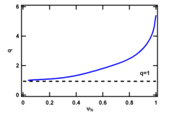
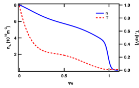
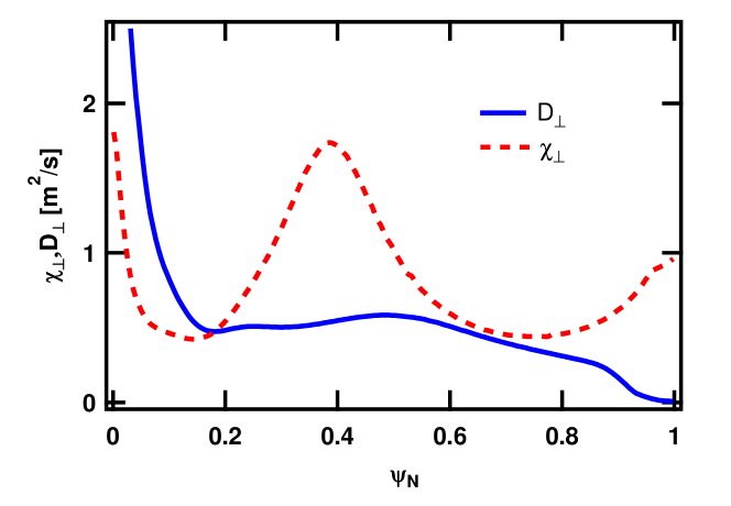
In our simulations, JOREK is initialized for an ASDEX-Upgrade like plasma: major radius , minor radius , toroidal field strength on axis , plasma current , edge safety factor . The full X-point plasma including the scrape-off layer up to simplified divertor targets are included in the simulation domain. The central electron density is , the central temperature is . The perpendicular heat diffusion coefficient is in the range . The parallel heat diffusion coefficient is proportional to with the value at the plasma center chosen to be about one order of magnitude lower than Spitzer-Härm predictions Spitzer and Härm (1953) since typically the heat flux limit Malone et al. (1975) reduces the parallel conductivity in the experiment Hoelzl et al. (2009). RMP currents are chosen around and scanned in a few simulations. The perpendicular electron background velocity is modified by changing the toroidal rotation velocity. Input profiles are given in Fig. 5. Input heat and particle diffusion profiles are shown in Fig. 7. The Lundquist number in the simulations is close to experimental conditions. The magnetic Prandtl number is chosen to be constant across the whole simulation domain such that viscosity is close to the collisional value estimated from the experimental data .
The most important effect missing in our simulations is the neoclassical toroidal viscosity, which would lead to a faster penetration of the magnetic perturbation and a penetration already at lower RMP coil currents or higher initial plasma rotation frequencies. We leave the implementation and study of this effect for future studies. A consistent evolution of the bootstrap current, which is available in the JOREK code for further studies, is also neglected since we are interested in particular in the seeding and penetration phases. In addition, the hysteresis effect investigated in Section III.6 can be studied this way independently of the the bootstrap current term simplifying the interpretation of the results.
III.3 Overview of the simulations performed
In the following, we give a brief overview of the simulations performed for this paper and refer to the respective sections, in which the results are discussed in detail.
Simulations at fully realistic Lundquist number for ASDEX Upgrade L-Mode experiments have been performed and reflect the qualitative change of the toroidal and electron perpendicular rotation profiles, however full penetration was not obtained (very likely due to the missing NTV effects). Thus, all simulations shown in the following are performed with values reduced by about a factor three to .
The typical process of mode seeding is shown and analyzed in III.4. The initial toroidal velocity used in the simulations is and RMP current . The thresholds for mode seeding in perturbation amplitude and rotation are studied in Section III.5 by means of the parameter scans shown in Table 1 and Table 2. The toroidal rotation was used as proxy to modify the perpendicular electron velocity as shown in Table 3.
Finally, simulations to study the hysteresis behaviour between ramp-up and ramp-down of the RMP coil currents are shown in section III.6. These simulations were performed with and the RMP current amplitudes shown in Table 4.
| Ramp-up | |||||||
|---|---|---|---|---|---|---|---|
| Ramp-down |
III.4 Typical simulation of mode penetration into an ASDEX Upgrade L-Mode plasma
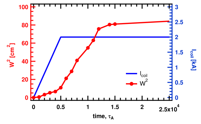
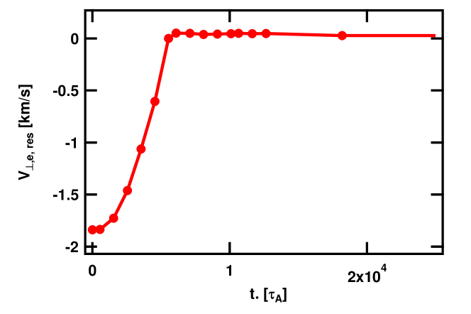
This section shows a typical simulation of mode penetration performed with and at . Like in the experimental observations shown in Section II, three phases are observed. First, the plasma exhibits a weak response to the applied perturbation. Once a specific threshold is reached (see Figure 1), mode growth accelerates until the final mode saturation at low perpendicular electron velocity is obtained. Time traces for the evolution of the island size and the perpendicular electron velocity at the rational surface are shown in Figures 8 and Figures 9, respectively.
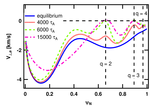
In the beginning, the island size is small and the perpendicular electron velocity at the rational surface is around . The electron velocity is given by , where the factor is a result of the assumption of having the same electron and ion temperatures in the model employed here (a model treating both temperatures differently is available as well). The rotation velocity has dropped by a factor of two after approximately and an accelerated growth of the island (mode penetration) sets in at around . The electron velocity comes to rest at the rational surface around and the saturation of the island starts around . Figure 8 shows the time evolution for the square of the island width which is proportional to the current perturbation at the resonant surface and, consequently, approximately proportional to the expected signals in magnetic pick up coils. The Figure also contains the prescribed evolution of the RMP coil currents. Note, that it is coincidence that saturation of the prescribed coil currents and onset of mode penetration take place approximately at the same time for this particular case (as proven by other simulations in our scans). For the perpendicular electron velocity at the rational surface shown in Figure 9, also radial profiles at several points in time are provided in Figure 10. Profiles are shown in the beginning of the simulation, before mode penetration sets in, during mode penetration, and in the saturated island state.
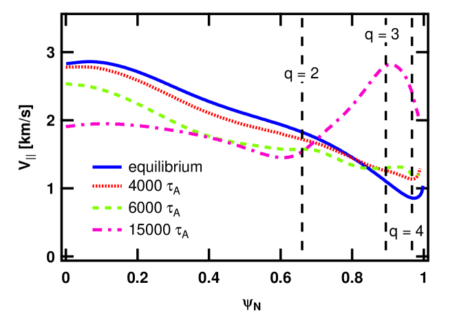
Initially the non-zero electron perpendicular velocity leads to the screening of the magnetic perturbation. However, the screening starts to drop due to the loss of the perpendicular component of the toroidal velocity (see Figure 11) and flatting of the temperature (see Figure 12) leading to a partial loss of the diamagnetic component. Once the condition is approximately satisfied, the transition phase is reached. In this phase, the perturbation propagates without screening forcing magnetic reconnection at the resonant surface. Similar to the experimental observations, the core toroidal velocity shown in Fig. 11 decreases.
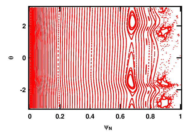
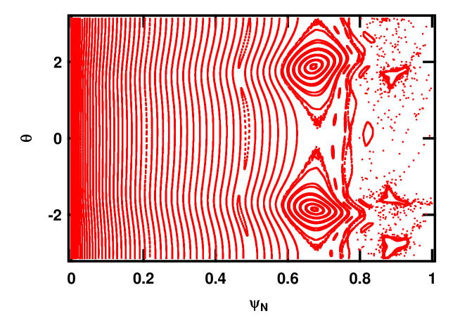
Figure 13 finally shows Poincare plots of the magnetic topology before mode penetration sets in and in the saturated island state. A considerable stochastisation of the plasma edge, and a large magnetic island can be seen.
III.5 Mode penetration thresholds in coil current and rotation velocity
Scans in both the plasma rotation velocity and the perturbation amplitude (coil currents) were carried out. The electron perpendicular velocity is modified in our scan by changing the toroidal velocity, while keeping the and diamagnetic drift effects unchanged. Table 3 shows how the perpendicular electron velocity is affected by our choice of the toroidal rotation velocity.
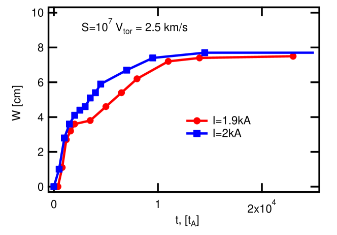
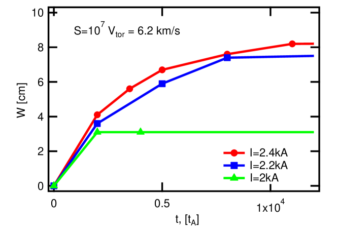
Scans in the perturbation amplitude for the values of toroidal velocity and are shown in Fig. 14 and Fig. 15 respectively. As the current in the RMP coils decreases, mode penetration slows down consistently with experimental observations (see Section II). Ultimately, if the perturbation is not strong enough, the electromagnetic torque cannot reduce the plasma rotation sufficiently to enter the penetration phase. The transition from weak response phase to the fully formed island phase was observed experimentally Fietz et al. (2015a). Also the time, required for the mode penetration, increased with decrease of the RMP current. The threshold for the transition to the penetrated state can only be compared qualitatively to the experimental observations due to limitations of our model. In particular, we believe that the lack of Neoclassical Toroidal Viscosity (NTV) in the simulations is our biggest limitation as it would provide a localized decrease in the rotation of the mode.
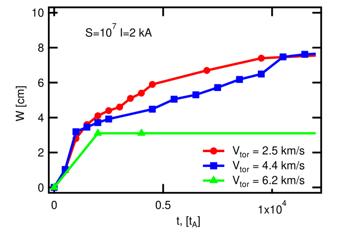
The scan in the plasma rotation shows a delay in the mode penetration as the initial toroidal velocity increases as seen in Figure 16. This is similar to moving from a lower to an upper curve in Figure 1. As predicted by the analytical model, if the rotation is strong enough for a given perturbation amplitude, there is no sufficient slow down of the plasma, and the RMP field thus remains partially screened like for the lower curve in Fig. 16.
It is interesting to point out that, in the case of mode penetration, the final saturated island size is defined solely by the current in RMP coils and is independent from the original plasma velocity. This can be seen in Figure 16, where the island size follows a universal square-root behaviour with respect to the applied coil currents for the penetrated states.
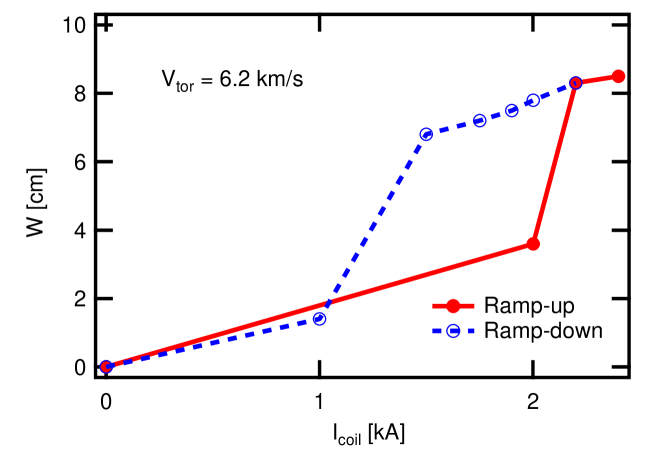
III.6 Simulation of the hysteresis in mode penetration between current ramp-up and ramp-down
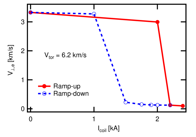
An additional set of simulations was performed to study the analytically predicted hysteresis between current ramp-up and ramp-down. As RMP current and associated torque increases, the steady state value for the perpendicular electron velocity at the rational surface gradually decreases. As seen for the solid curve in Figure 17, a ”jump” is observed to a low rotational state at a coil current of about . As seen in Figure 18, this corresponds to a ”jump” to a large island size, thus to mode penetration.
When the coil current is ramped down now again starting from the steady state solution of the simulation with coil current, the island remains in the penetrated state with low perpendicular electron velocity at the rational surface and large island size significantly longer (dashed line in Figures 17 and 18). The back-transition appears only around a coil current of . This implies that a decrease of the perturbation amplitude only slightly below the penetration threshold does not cause a significant decrease of the island size. The small drop of the island size is only given by the square-root dependency of the penetrated island size to the perturbation amplitude. In case of significant pressure gradients, the additional bootstrap current drive can lead to a non-linearly unstable island such that the island remains present even if the external perturbation is switched off entirely again (NTM). The bootstrap current drive is neglected in the present study due to the low pressure gradients in the considered L-Mode plasma.
III.7 Evolution of kink/bending and tearing responses during mode penetration
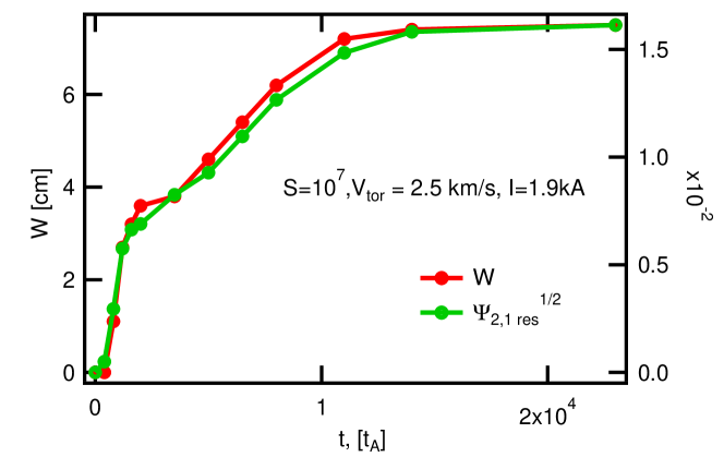
In this Section, the transition from kink/bending111the term bending is preferred e.g. in Ref Ferraro2012) over kinking; we use both terms synonymously since both of them are common in literature to tearing response is briefly investigated for one of our simulations. This topic was discussed before e.g., in Refs. Igochine et al. (2014, 2017); Yu et al. (2012). Figure 19 shows the evolution of the island size over time across the mode penetration time. At the same time, the square-root of at the rational surface is plotted. Both curves show excellent agreement, verifying that the perturbed poloidal magnetic flux at the rational surface is a very good measure for the island size. This, however is not necessarily true for magnetic measurements at coil locations where the decay of the signals has to be taken into account properly and the plasma response between island location and measurement location can additionally alter the signals.
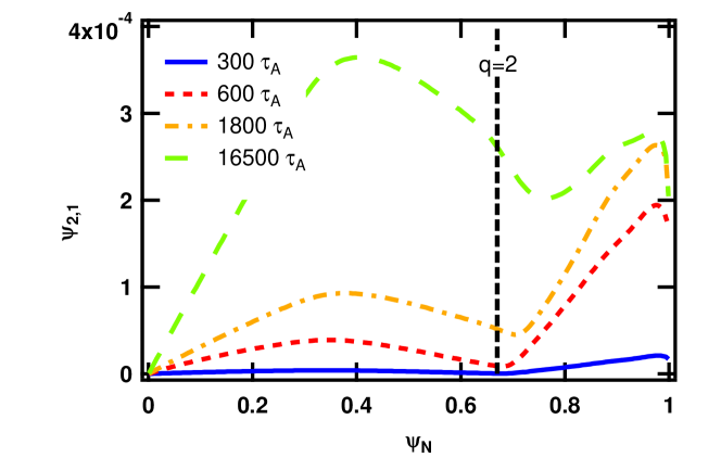
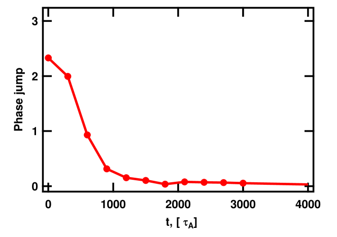
Figure 20 shows how the absolute value of the magnetic perturbation grows with time. In Figure 21 it is depicted how the phase jump of this perturbation across the rational surface is changing with time. With phase jump, we refer to the difference of the phase of the poloidal flux between locations outside the rational surface () and inside the rational surface (). A phase jump close to , as it is seen initially, indicates a dominant kink/bending parity of the magnetic perturbation. A phase jump close to zero, like it is approached already after about 1000 Alfvén times indicates a dominant tearing parity of the magnetic perturbation.
IV Conclusions
Tearing mode seeding by magnetic perturbations has been studied in tokamak X-point geometry both experimentally and numerically and was compared to analytical theory. As a source for the magnetic perturbation, resonant magnetic perturbation coils are used, although our results are fully transferable to other sources like sawtooth crashes Loizu and Helander (2017). The simulations were carried out with the non-linear two-fluid MHD code JOREK. Input parameters close to the experimental ones were chosen, however simulations were performed at slightly reduced Lundquist number and increased coil currents. This was done to compensate for missing NTV effects not accounted for in the simulations.
All three phases of mode penetration observed in the experiment were also obtained in the simulations: ”weak” response, a fully formed island state and the transition between these two regimes called penetration. A drop of the core toroidal rotation during the penetration is also observed, similar to experiments, however the drop in the simulations is weaker due to the absence of NTV in our simulations. The decay of the electron perpendicular velocity is consistent with experimental observations, meaning that the drop of to 0 corresponds to the mode penetration in both cases. The simulation results were compared to the analytical model for MP penetration derived in cylindrical geometry. Scans in toroidal plasma rotation and perturbation amplitude confirm the analytically predicted thresholds for the fast transition into low rotation regime. A hysteresis between the RMP current ramp-up and ramp-down was observed like analytically predicted as well. We confirmed a fast formation of the kink/bending response and a delayed tearing response at the rational surface.
Acknowlegments
This work was carried out under the auspices of the Max-Planck-Princeton Center for Plasma Physics. This work has been carried out within the framework of the EUROfusion Consortium and has received funding from the Euratom research and training program 2014-2018 and 2019-2020 under grant agreement No 633053. The views and opinions expressed herein do not necessarily reflect those of the European Commission.
Some of the simulations were performed on the Marconi-Fusion supercomputer located at CINECA, Italy.
The authors would like to thank E. Strumberger, Q. Yu, V. Bandaru, E. Viezzer and F. Wieschollek for fruitful discussions.
References
- Biskamp [1993] D. Biskamp. Nonlinear Magnetohydrodynamics. Cambridge University Press, Cambridge, England, 1993.
- Chang et al. [1998] Z. Chang, E. D. Fredrickson, S. H. Batha, M. G. Bell, R. V. Budny, F. M. Levinton, K. M. McGuire, G. Taylor, and M. C. Zarnstorff. Neoclassical tearing modes in tokamak fusion test reactor experiments. i. measurements of magnetic islands and Δ′. Physics of Plasmas, 5(4):1076–1084, 1998. doi: 10.1063/1.872627.
- Smolyakov [1993] A I Smolyakov. Nonlinear evolution of tearing modes in inhomogeneous plasmas. Plasma Physics and Controlled Fusion, 35(6):657, 1993. URL http://stacks.iop.org/0741-3335/35/i=6/a=002.
- Zohm et al. [2001] H. Zohm, G. Gantenbein, A. Gude, S. Günter, F. Leuterer, M. Maraschek, J. Meskat, W. Suttrop, and Q. Yu. Neoclassical tearing modes and their stabilization by electron cyclotron current drive in asdex upgrade. Physics of Plasmas, 8(5):2009–2016, 2001. doi: 10.1063/1.1344564.
- Fitzpatrick [1995] Richard Fitzpatrick. Helical temperature perturbations associated with tearing modes in tokamak plasmas. Physics of Plasmas, 2(3):825–838, 1995. doi: 10.1063/1.871434.
- Drake et al. [1983] J. F. Drake, T. M. Antonsen, A. B. Hassam, and N. T. Gladd. Stabilization of the tearing mode in high‐temperature plasma. The Physics of Fluids, 26(9):2509–2528, 1983. doi: 10.1063/1.864441.
- Scott et al. [1985] Bruce D. Scott, J. F. Drake, and A. B. Hassam. Nonlinear stability of drift-tearing modes. Phys. Rev. Lett., 54:1027–1030, Mar 1985. doi: 10.1103/PhysRevLett.54.1027.
- Scott and Hassam [1987] Bruce D. Scott and A. B. Hassam. Analytical theory of nonlinear drift‐tearing mode stability. The Physics of Fluids, 30(1):90–101, 1987. doi: 10.1063/1.866065.
- Waelbroeck [1989] F. L. Waelbroeck. Current sheets and nonlinear growth of the m=1 kink‐tearing mode. Physics of Fluids B: Plasma Physics, 1(12):2372–2380, 1989. doi: 10.1063/1.859172.
- Meshcheriakov et al. [2012] Dmytro Meshcheriakov, Patrick Maget, Hinrich Lütjens, Peter Beyer, and Xavier Garbet. Linear stability of the tearing mode with two-fluid and curvature effects in tokamaks. Physics of Plasmas, 19(9):092509, 2012. doi: 10.1063/1.4754000.
- Gude et al. [1999] A. Gude, S. Günter, S. Sesnic, and ASDEX Upgrade Team. Seed island of neoclassical tearing modes at asdex upgrade. Nuclear Fusion, 39(1):127, 1999. doi: 10.1088/0029-5515/39/1/308.
- Sauter et al. [2002] O Sauter, R J Buttery, R Felton, T C Hender, D F Howell, and contributors to the EFDA-JET Workprogramme. Marginal β-limit for neoclassical tearing modes in jet h-mode discharges. Plasma Physics and Controlled Fusion, 44(9):1999, 2002. URL http://stacks.iop.org/0741-3335/44/i=9/a=315.
- La Haye [2006] R. J. La Haye. Neoclassical tearing modes and their control. Physics of Plasmas, 13(5):055501, 2006. doi: 10.1063/1.2180747.
- Igochine et al. [2014] V. Igochine, A. Gude, S. Günter, K. Lackner, Q. Yu, L. Barrera Orte, A. Bogomolov, I. Classen, R. M. McDermott, N. C. Luhmann Jr., and ASDEX Upgrade Team. Conversion of the dominantly ideal perturbations into a tearing mode after a sawtooth crash. Physics of Plasmas, 21, 2014.
- Igochine et al. [2017] V. Igochine, I. Classen, M. Dunne, A. Gude, S. Günter, K. Lackner, R.M. McDermott, M. Sertoli, D. Vezinet, M. Willensdorfer, Q. Yu, H. Zohm, and ASDEX Upgrade Team. Tearing mode formation induced by internal crash events at different . Nuclear Fusion, 57(3), 2017.
- Ara et al. [1978] G. Ara, B. Basu, B. Coppi, G. Laval, M. N. Rosenbluth, and B. V. Waddell. Magnetic reconnection and m=1 oscillations in current carrying plasmas. Annals of Physics, 112:443–476, 1978.
- Waelbroeck et al. [2001] F. L. Waelbroeck, J. W. Connor, and H. R. Wilson. Finite larmor-radius theory of magnetic island evolution. Physical Review Letters, 87(21):103501, 2001. doi: 10.1103/PhysRevLett.87.215003.
- Glasser et al. [1976] A. H. Glasser, J. M. Greene, and J. L. Johnson. Resistive instabilities in tokamak. Physics of Fluids, 19, 1976.
- Fitzpatrick [1993] R. Fitzpatrick. Interaction of tearing modes with external structures in cylindrical geometry. Nuclear Fusion, 33(7), 1993.
- Nardon et al. [2010] E. Nardon, P. Tamain, M. Bécoulet, G. Huysmans, and F.L. Waelbroeck. Quasi-linear MHD modelling of h-mode plasma response to resonant magnetic perturbations. Nuclear Fusion, 50, 2010.
- Orain et al. [2013a] F. Orain, M. Becoulet, G. Dif-Pradalier, G. Huijsmans, S. Pamela, E. Nardon, C. Passeron, G. Latu, V. Grandgirard, A. Fil, A. Ratnani, I. Chapman, A. Kirk, A. Thornton, M. Hoelzl, and P. Cahyna. Non-linear magnetohydrodynamic modeling of plasma response to resonant magnetic perturbations. Phys. Plasmas, 20:102510, 2013a.
- Huysmans and Czarny [2007] G.T.A. Huysmans and O. Czarny. MHD stability in x-point geometry: simulation of ELMs. Nuclear Fusion, 47(7):659, 2007. doi: 10.1088/0029-5515/47/7/016.
- Czarny and Huysmans [2008] Olivier Czarny and Guido Huysmans. Bezier surfaces and finite elements for MHD simulations. Journal of Computational Physics, 227(16):7423 – 7445, 2008. ISSN 0021-9991. doi: 10.1016/j.jcp.2008.04.001.
- Orain et al. [2013b] F. Orain, M. Bécoulet, G. Dif-Pradalier, G. Huijsmans, S. Pamela, E. Nardon, C. Passeron, G. Latu, V. Grandgirard, A. Fil, A. Ratnani, I. Chapman, A. Kirk, A. Thornton, M. Hoelzl, and P. Cahyna. Non-linear magnetohydrodynamic modeling of plasma response to resonant magnetic perturbations. Physics of Plasmas, 20(10):102510, 2013b. doi: 10.1063/1.4824820.
- Fietz et al. [2015a] S. Fietz, R. Coelho, I. Classen, M. Maraschek, W. Suttrop, H. Zohm, the EUROfusion MST1 Team, and the ASDEX Upgrade Team. Study of suppressed tearing modes seeded with non-axsisymmetric magnetic perturbation fields at the asdex upgrade tokamak. proc. 42nd EPS conf. plasm. phys., P1.123, 2015a.
- Kallenbach et al. [2017] A. Kallenbach, ASDEX Upgrade Team, and EUROfusion MST1 Team. Overview of ASDEX Upgrade results. Nuclear Fusion, 57(10):102015, 2017. doi: 10.1088/1741-4326/aa64f6.
- Fietz et al. [2015b] S. Fietz, A. Bergmann, I. Classen, M. Maraschek, M. Garcia-Munoz, W. Suttrop, H. Zohm, and the ASDEX Upgrade Team. Influence of externally applied magnetic perturbations on neoclassical tearing modes at ASDEX Upgrade. Nuclear Fusion, 55(1):013018, 2015b. doi: 10.1088/0029-5515/55/1/013018.
- Viezzer et al. [2012] E. Viezzer, T. Pütterich, R. Dux, and R. M. McDermott. High-resolution charge exchange measurements at asdex upgrade. Review of Scientific Instruments, 83(10):103501, 2012. doi: 10.1063/1.4755810.
- McDermott et al. [2014] R.M. McDermott, C. Angioni, G.D. Conway, R. Dux, E. Fable, R. Fischer, T. Putterich, F. Ryter, E. Viezzer, and the ASDEX Upgrade Team. Core intrinsic rotation behaviour in ASDEX upgrade ohmic l-mode plasmas. Nuclear Fusion, 54, 2014.
- Viezzer et al. [2013] E. Viezzer, T. Pütterich, C. Angioni, A. Bergmann, R. Dux, E. Fable, R.M. McDermott, U. Stroth, and E. Wolfrum and. Evidence for the neoclassical nature of the radial electric field in the edge transport barrier of ASDEX upgrade. Nuclear Fusion, 54(1):012003, dec 2013. doi: 10.1088/0029-5515/54/1/012003. URL https://doi.org/10.1088%2F0029-5515%2F54%2F1%2F012003.
- Waelbroeck [2003] F. L. Waelbroeck. Shielding of resonant magnetic perturbations in the long mean-free path regime. Physics of Plasmas, 10(10):4040–4047, 2003. doi: 10.1063/1.1607324.
- Nardon et al. [2007] E. Nardon, M. Bécoulet, G. Huysmans, and O. Czarny. Magnetohydrodynamics modelling of h-mode plasma response to external resonant magnetic perturbations. Physics of Plasmas, 14(9):092501, 2007. doi: 10.1063/1.2759889.
- Heyn et al. [2008] Martin F. Heyn, Ivan B. Ivanov, Sergei V. Kasilov, Winfried Kernbichler, Ilon Joseph, Richard A. Moyer, and Alexey M. Runov. Kinetic estimate of the shielding of resonant magnetic field perturbations by the plasma in DIII-d. Nuclear Fusion, 48(2):024005, jan 2008. doi: 10.1088/0029-5515/48/2/024005. URL https://doi.org/10.1088%2F0029-5515%2F48%2F2%2F024005.
- Bécoulet et al. [2014] M. Bécoulet, F. Orain, G. T. A. Huijsmans, S. Pamela, P. Cahyna, M. Hoelzl, X. Garbet, E. Franck, E. Sonnendrücker, G. Dif-Pradalier, C. Passeron, G. Latu, J. Morales, E. Nardon, A. Fil, B. Nkonga, A. Ratnani, and V. Grandgirard. Mechanism of edge localized mode mitigation by resonant magnetic perturbations. Phys. Rev. Lett., 113:115001, Sep 2014. doi: 10.1103/PhysRevLett.113.115001.
- Strauss [1997] H. R. Strauss. Reduced mhd in nearly potential magnetic fields. Journal of Plasma Physics, 57(1):83–87, 1997.
- Franck, Emmanuel et al. [2015] Franck, Emmanuel, Hoelzl, Matthias, Lessig, Alexander, and Sonnendrücker, Eric. Energy conservation and numerical stability for the reduced MHD models of the non-linear JOREK code. ESAIM: M2AN, 49(5):1331–1365, 2015. doi: 10.1051/m2an/2015014.
- Hazeltine et al. [1985] R. D. Hazeltine, M. Kotschenreuther, and P. J. Morrison. A four-field model for tokamak plasma dynamics. Physics of Fluids, 28(8):2466–2477, 1985.
- Gianakon et al. [2002] T. A. Gianakon, S. E. Kruger, and C. C. Hegna. Heuristic closure for numerical simulations of neoclassical tearing modes. Physics of Plasmas, 9(2):536–547, 2002. doi: 10.1063/1.1424924.
- Spitzer and Härm [1953] Lyman Spitzer and Richard Härm. Transport phenomena in a completely ionized gas. Phys. Rev., 89:977–981, Mar 1953. doi: 10.1103/PhysRev.89.977.
- Malone et al. [1975] R. C. Malone, R. L. McCrory, and R. L. Morse. Indications of strongly flux-limited electron thermal conduction in laser-target experiments. Phys. Rev. Lett., 34:721–724, Mar 1975. doi: 10.1103/PhysRevLett.34.721.
- Hoelzl et al. [2009] M. Hoelzl, S. Günter, I.G.J. Classen, Q. Yu, the TEXTOR Team, and E. Delabie. Determination of the heat diffusion anisotropy by comparing measured and simulated electron temperature profiles across magnetic islands. Nuclear Fusion, 49(11):115009, 2009. doi: 10.1088/0029-5515/49/11/115009.
- Note [1] Note1. the term bending is preferred e.g. in Ref Ferraro2012) over kinking; we use both terms synonymously since both of them are common in literature.
- Yu et al. [2012] Q. Yu, S. Günter, K. Lackner, and M. Maraschek. Seed island formation by forced magnetic reconnection. Nuclear Fusion, 52:063020, 2012. doi: 10.1088/0029-5515/52/6/063020.
- Loizu and Helander [2017] J. Loizu and P. Helander. Unified nonlinear theory of spontaneous and forced helical resonant mhd states. Physics of Plasmas, 24, 2017. doi: 10.1063/1.4979678.
- Hölzl et al. [2012] M. Hölzl, S. Günter, R.P. Wenninger, W.-C. Mueller, G. T. A. Huysmans, K. Lackner, I. Krebs, and ASDEX Upgrade Team. Reduced-MHD simulations of toroidally and poloidally localized elms. Physics of Plasmas, 19:082505, 2012. doi: 10.1063/1.4742994.
Chapter \thechapter Normalization
We list a few normalization parameters for our simulations for reference. The normalization is described, e.g., in Ref. Hölzl et al. [2012].
| (9) | ||||
| (10) | ||||
| (11) | ||||
| (12) | ||||
| (13) | ||||
| (14) |