Bragg’s reflection for walking droplets in 1D crystals
††preprint: DRAFT v1.6 -A walking droplet possesses fascinating properties due to its peculiar wave/particle interaction. The self-propelling motion of such a droplet is driven by the Faraday instability triggered around the droplet at each impact. We studied in this article how such a droplet behaves in an annular cavity where a periodic pattern is placed underneath the liquid-air interface, altering the Faraday instability. We show that, while the annulus ensures a circular motion of the droplet, the periodic pattern affects the global droplet motion. Similarly to electromagnetic waves in photonic crystals, the average droplet speed nearly vanishes when the pattern has a characteristic length close to half the Faraday wavelength. This effect opens ways to design guides, reflectors, lattices and metamaterials for such macroscopic particles.
When a millimetric droplet is gently placed on an air-liquid interface vibrated with an amplitude and a frequency it is able to bounce without coalescing when the bath maximum dimensionless acceleration is above a threshold (Couder2005, ; Terwagne2013, ; Hubert2015, ). An air layer separates the droplet from the vibrated surface preventing coalescence by lubrication Gilet2010 . Depending on , various bouncing modes can be observed, from simple bounces to period doubling and much more complex bouncing dynamics (Wind2013, ; Terwagne2013, ). Once another threshold is reached, a parametric instability is triggered: the Faraday instability Kumar1996 . By approaching the Faraday instability from below, the droplet starts to bounce once every two periods, and triggers Faraday waves which possess a wavelength being fixed by the forcing parameters (Couder2005n, ; Protiere2006, ). For , due to the coupling between the droplet and the sum of waves emitted on the liquid surface by the successive previous impacts, bouncing droplets start to move horizontally along the liquid Couder2005n . They are called walkers (Protiere2006, ) and is named the walking threshold. The droplet-wave interaction leads to spectacular physical phenomena at a macroscopic scale: single walkers may exhibit tunneling effect (Eddi2009, ), diffraction and interference around apertures (Couder2006, ), revolution orbits (Protiere2008, ), splitting of energy levels (Eddi2012, ) and quantification of macroscopic observables (Perrard2014, ; Labousse2014, ). Resonances (Harris2013, ) and coherent wave packets Filoux2015 were also investigated above cavities. In all these reported phenomena, the major ingredient is the Faraday standing wave pattern which imposes a length scale to the system.
In a recent study Filoux2017 , we demonstrated that the Faraday instability can be triggered locally by carving underwater cavities in order to guide the walking droplets along well defined paths. Wave-mediated transport phenomena can therefore be investigated. In particular, classical waves are deeply affected by the presence of a periodic media such that transport could vanish in some situations like in the Bragg’s reflector case Bragg . In this paper, we address the following fundamental question : what is the behavior of a walking droplet when perturbed by some underlying periodic pattern?
The experimental conditions for the droplet and the bath are detailed in Methods. Identical droplets are created by an automatic generator described in Ref. (Terwagne2013, ). The liquid used in experiments is silicon oil. The container is shaken vertically by an electromagnetic system with a tunable amplitude and a fixed frequency Filoux2017 . The dimensionless maximum acceleration is measured with an accelerometer and is adjusted to find the bouncing and walking regimes close to the Faraday instability. In an isotropic medium without any underwater carvings, the wavelength has been estimated to be about in a large square container Filoux2015 . The characteristic of the Faraday instability are highly dependent of the liquid depth since the dispersion relation of gravity-capillary waves is given by
| (1) |
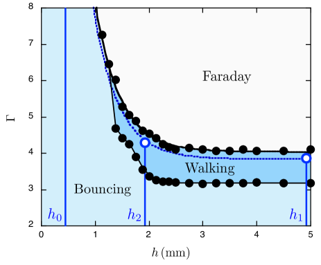
which gives roughly the measured value of when , being the local depth of the fluid. Also, the occurence of the Faraday instability depends strongly of when given . Figure 1 shows the Faraday threshold , as well as the walking threshold , for a droplet as a function of liquid depth in a large square cavity. Above mm, the behavior of both the droplet and the liquid surface are independent of while below mm, the bouncing regime vanishes and the Faraday regime only takes place on relatively important acceleration.
results
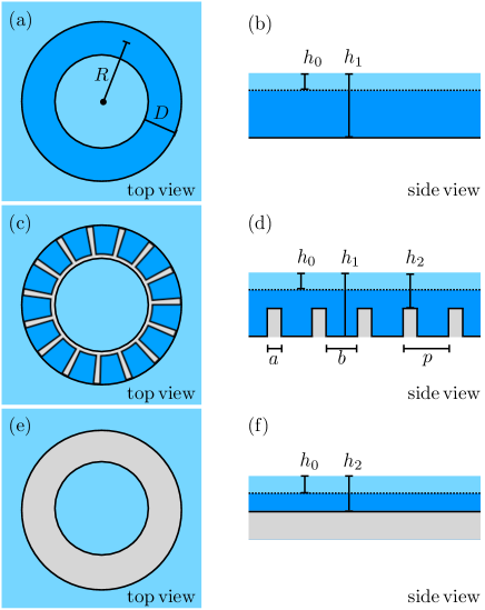
Based on the results of Figure 1, we have proposed in recent works Filoux2015 ; Filoux2017 to study droplets in an annulus, as sketched in Figures 2(a,b). We decided to set the annulus mean radius to mm. The liquid depth in the center of the cavity is and the width of the annular channel is . This width has been demonstrated to be the optimal value for obtaining the best circular motion Filoux2017 . Elsewhere, the liquid depth is fixed to 0.4 mm, limiting the propagation of waves. Note that such shallow water areas are never explored by the droplet. Indeed, at this depth, a droplet may bounce but cannot walk as noticed in Figure 1. Observations show that typical trajectories of single walkers above the annular cavity of Figure 2(a,b) are circles. There is no central force behind the global circular trajectory. The fact that the droplet follows the annulus is that the Faraday waves adopt the symmetry of the cavity. In the azimutal direction, waves can be approximated to sinusoidal standing waves, as expected for a 1D system. In the transverse direction, i.e. in the radial direction, the waves present large amplitudes in the center of the cavity and evanescent waves are strongly damped outside the annulus. A relevant question here is to define and measure the Faraday wavelength in the present quasi 1D-system. Indeed, the presence of the annulus carved underneath the liquid surface affects the wavelength value. By measuring the quantified interdistances between droplet pairs moving along the same circular trajectory, we have demonstrated Filoux2015 that the natural wavelength triggered by droplets is . Note that .
While the clockwise or anticlockwise droplet motion in the annulus depends on the initial conditions, the speed of a walker is fixed by the forcing parameters of the experiment as well as the geometry of the cavity Filoux2017 . In our experiments, the acceleration is always kept at . The Faraday waves are damped such that the liquid surface keeps the trace of about previous impacts. For those experimental conditions, the walker speed is . We will use this typical speed as a reference in the following. In order to affect the motion of the droplet similarly to Bragg’s refractor, we place a periodic pattern inside the annulus to impose a different length scale, as sketched in Figures 2(c,d). It consists in a number of rectangular barriers of width separated by a distance . The periodic length is therefore . On the barriers, the liquid depth is reduced down to mm. We measured the speed of droplets at Me=20 for this specific depth : mm/s, i.e. . This specific depth corresponds to Figures 2(e,f). Assuming that each barrier is decreasing the speed of the droplet, we will consider periodic patterns for which the ratio is kept constant whatever the value of . Therefore, we expect a time-average speed given by
| (2) |
whatever the number of barriers. Several periodic patterns have been created from to with a fixed ratio . From the above equation, we expect .
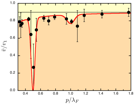
From about 400 independent experiments with constant forcing parameters, Figure 3 presents the average normalized speed of walkers obtained by tracking the particles in the various cavities, as a function of the ratio . When is much larger than , the ratio is close to the expected value, given by Eq.(2), and indicated by the thin horizontal line. However, the average speed ratio is slightly decreasing with , due to the increase of the number of underneath barriers slowing down the droplet. We will obtain some evidence of that effect below. The striking feature of the plot is that one observes a sharp and significant drop of meaning that the behavior of the droplet is deeply affected by the underlying pattern. It is worth noticing that such event takes place when approaching
| (3) |
which corresponds to the Bragg’s condition Bragg . The analogy between Bragg’s reflection in optical lattices and our fluidic system is striking, even though major differences should be remarked. First, for classical light propagation in a 1D periodic layered medium, the wavelength is modified from one layer to the other one such that becomes the optical path slightly different from layer thickness. However, this is not the case herein since no wavelength variations have been observed. Second, the waves emitted by the walker are stationnary and does not propagate into the channel. Only their source (the walking drop) moves within the guide. Please note that higher order effects, at integer multiples of , have not been observed except that a small drop seems to take place around with larger error bars. The red curve in Figure 3 is a guide for the eye emphasizing the main features of our results.
To obtain a deeper understanding of this dynamics, figure 4 presents the angular-time trajectories of the droplets in two cases: (a) (i.e. ) and (b) (i.e. ). The latter corresponds to the Bragg condition for which the average speed vanishes. On both plots, the instantaneous speed are nearly constant. If one looks closely, one observes small undulations corresponding to the crossing of the successive barriers. Each time the droplet is passing a barrier, it decelerates and accelerates again. The speed oscillations are weak for . However, for the case , the droplet deceleration is so high that the droplet may stop and may turn back. Actually, the walking droplet makes random back-and-forth trajectories. Averaging this particular motion over long times leads to a vanishing average speed , while the instantaneous speed is nonzero. This behavior explains why large error bars are found in Figure 3 at the Bragg condition. A video is given in the supplementary materials in order to illustrate the particular droplet motion near obstacles. It seems that the droplet speed decreases at each obstacle crossing. The origin of the speed oscillations observed at the Bragg condition should be found in the Faraday wavefield around the walking droplet.
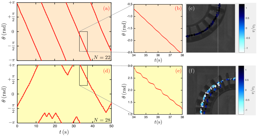
Let us now try to model this walking dynamics, and for this purpose let us look back at Fig.4. Comparing Figs.4(b) and 4(e), one sees that the short-time average speed of the walker changes depending on the value of (i.e. ). Indeed, in Fig.4(b) the walker average angular speed within the channel is about rad/s while in Fig.4(e) this speed does not even reach rad/s. Since the propulsive mechanism comes from the wave, one concludes that the presence of the submarine pattern has altered their generation. An explanation can be found in delon ; Feng ; Osipov . In those studies, the authors focus on the appearance of Faraday waves with a submarine periodic pattern. It is shown that there exist wavelength of corrugated bottoms cancelling the Faraday instability, similarly to forbidden bands in solid-state physics. The corresponding condition writes
| (4) |
where is the wavelength of the submarine obstacle. Please note that this condition has been obtained in a “true” channel. Our system only considers a channel carved underneath the surface: evanescent waves exist outside the channel boundaries. This observation explains why the walker still walks for “Bragg’s conditions”: because of boundary conditions in our experimental setup are smoother than in theoretical analysis, waves are still emitted but expected to be of smaller amplitude. The amplitude being smaller, the short term velocity of the droplet is also expected to be smaller, as observed in Figs. 4(b) and 4(e).
Discussion
Let us consider the following numerical model for the walking dynamics. The numerical scheme is the one used in Ref.Borghesi2014 ; Labousse2016 . It consists in an event-driven algorithm where the walker motion is actuated in parallel of the wave dynamics. The walker alternates two phases: a parabolic flight above the liquid surface and a contact with the liquid surface. During the first phase, the droplet is only submitted to external forces while during the second phase, friction with the air layer leads to a loss of speed. In between, at each impact, a standing cylindrical wave is generated. Simultaneously, the walker gets a kick of momentum in the direction of the gradient of the total wavefield. A precise mathematical description of the algorithm can be found in Labousse2016 . Note that in those numerical simulations, the exact shape of the wavefield is assumed to be the superposition of waves with the shape where is the wave amplitude and the center of the wave emitted. Therefore, the effect of the submarine obstacles are not taken into account and needs to be added by hand in the simulation. We use the ansatz theorized in Hubert2017 : we account for the submarine obstacle by using an external potential . The direction accounts for the confinement due to the annulus while the direction contains the periodic potential. As a consequence, we assume the following external potential
| (5) |
where is the amplitude of the wavy external potential per mass unit. In this expression, the value of is chosen such as the width of the potential fits the width of the experimental channel, following the relation . In simulation, one uses . Finally, we also known, as discussed before, that the wave amplitude decreases when approaching the Bragg’s condition. As a consequence, the amplitude is also expected to be changed.
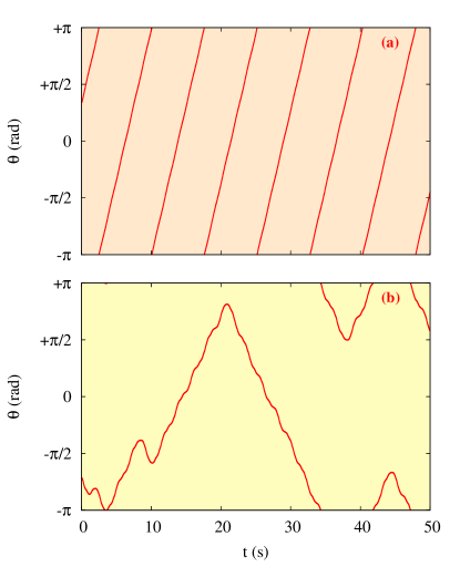
Figure 5 illustrates the dynamics of the walker in numerical simulation for two different amplitude of emitted waves, namely (a) and (b) and identical periodicity . The wavy external potential is J/kg, which is comparable to the energy along the direction. The equilibrium radius has been chosen such that it matches the experimental one. Note that the memory has been kept constant in each simulation with . One can see that the dynamics observed mimics the experimental one, validating our hypothesis: a change of the wavefield amplitude indeed allows the walker to be reflected by the external potential, similarly to the studies of Eddi et al Eddi2009 and later explained theoretically by Hubert et al Hubert2017 . As the amplitude of the wavefield gets smaller at the Bragg’s condition, the active mechanism propelling the droplet gets weaker. In this condition, when the droplet comes forward a shallow area region, it acts as a repulsive potential which might repeal the walker. This simple numerical experiment allows for three conclusions. First, the dynamics shows in Fig.3 only comes from the hydrodynamic and can be explained through the appearance of the Faraday instability. Secondly, this is the walker weaker active mechanism (and therefore lower speed) that explains the reflection above submarine obstacles. Finally, one has to understand that contrarily to “true” Bragg reflection, the walker dynamics changes because of a change of wave amplitude instead of a change of wavelength.
In summary, we evidenced from experimental measurements that a Bragg condition exists for the transport of droplets above periodic patterns. This effect is seen to originate from the pinning of the Faraday standing wave on the underneath pattern. This Bragg-like remarkable phenomenon can be exploited for creating resonators, metamaterials and other systems for guiding walking droplets.
Methods
The experimental conditions for the droplet and bath are the following. Identical tiny droplets are created by an automatic generator as fully described in (Terwagne2013, ). The resulting diameter of each droplet is close to 800 . The liquid is silicon oil with a kinematic viscosity of 20 cSt, density and surface tension . The container is shaken vertically by an electromagnetic system with a tunable amplitude and a fixed frequency . An accelerometer is fixed on the vibrating plate and delivers a tension proportional to the acceleration. The dimensionless maximum acceleration is tuned for finding the bouncing and walking regimes close to the Faraday instability. The acceleration is always kept at in our experiments. This corresponds to a so-called “low memory regime” since Faraday waves are damped such that the liquid surface keeps the trace of a few previous impacts. The wavelength has been estimated to about .
Acknowledgments – This work was financially supported by the Actions de Recherches Concertées (ARC) of the Belgium Wallonia- Brussels Federation under Contract No. 12-17/02. We thank also S.Dorbolo for fruitful discussions.
Supplementary Information
A movie is given : a droplet moving in the annulus were a periodic pattern of barriers is placed, fulfilling the Bragg condition. The droplet has a random back-and-forth motion.
Authors Contributions Statement – BF collected and analyzed experimental data. Physical interpretations were provided by BF, MH and NV. Simulations were performed by MH. This manuscript was written by MH and NV.
Competing Interests – The authors declare that they have no competing financial interests.
References
- (1) Couder Y., Fort E., Gautier C-H. & Boudaoud A. From bouncing to floating: Noncoalescence of drops on a fluid bath. Phys. Rev. Lett. 94, 177801 (2005).
- (2) Terwagne D., Ludewig F., Vandewalle N. & Dorbolo S. The role of the droplet deformations in the bouncing droplet dynamics. Phys. Fluids 25, 122101 (2013).
- (3) Hubert M., Robert D., Caps H., Dorbolo S. & Vandewalle N. Resonant and antiresonant bouncing droplets. Phys. Rev. E 91, 023017 (2015).
- (4) T.Gilet, D.Terwagne, N.Vandewalle & S.Dorbolo, Dynamics of a bouncing droplet onto a vertically vibrated interface, Phys. Rev. Lett. 100, 167802 (2008)
- (5) Wind-Willassen Ø., Moláček J., Harris D. M. & Bush J. W. M. Exotic states of bouncing and walking droplets. Phys. Fluids 25, 082002 (2013).
- (6) Kumar K. Linear theory of Faraday instability in viscous liquids. Proc. R. Soc. Lond. A452, 1113 (1996).
- (7) Couder Y., Protière S., Fort E. & Boudaoud A. Dynamical phenomena: Walking and orbiting droplets. Nature 437, 208 (2005).
- (8) Protière S., Boudaoud A. & Couder Y. Particle-wave association on a fluid interface. J. Fluid. Mech. 554, 85 (2006).
- (9) Eddi A., Fort E., Moisy F. & Couder Y. Unpredictable tunneling of a classical wave-particle association. Phys. Rev. Lett. 102, 240401 (2009).
- (10) Couder Y. & Fort E. Single-particle diffraction and interference at a macroscopic scale. Phys. Rev. Lett. 97, 154101 (2006).
- (11) Protière S., Bohn. S. & Couder Y. Exotic orbits of two interacting wave sources. Phys. Rev. E 78, 036204 (2014).
- (12) Eddi A., Moukhtar J., Perrard S., Fort E. & Couder Y. Level Splitting at Macroscopic Scale. Phys. Rev. Lett. 108, 264503 (2012).
- (13) Perrard S., Labousse M., Miskin M., Fort E. & Couder Y. Self-organisation into quantized eigenstates of a classical wave-driven particle. Nat. Comm. 5, 3219 (2014).
- (14) Labousse M., Perrard S., Couder Y. & Fort E. Build-up of macroscopic eigenstates in a memory-based constrained system. New J. Phys. 16, 113027 (2014).
- (15) Harris D. M., Moukhtar J., Fort E., Couder Y. & Bush J. W. M. Wavelike statistics from pilot-wave dynamics in a circular corral. Phys. Rev. E 88, 011001(R) (2013).
- (16) Filoux B., Hubert M., & Vandewalle N. Strings of droplets propelled by coherent waves. Phys. Rev. E 92, 041004(R) (2015).
- (17) Filoux B., Hubert M., Schlagheck P. & Vandewalle N. Walking droplets in linear channels. Phys. Rev. Fluids 2, 013601 (2017).
- (18) Bragg, W.H. & Bragg, W.L. The Reflexion of X-rays by Crystals. Proc. R. Soc. Lond. A. 88, 428 (1913).
- (19) G.Delon et al. Faraday instability on a network. Chaos 20, 041103 (2010).
- (20) Feng J., Jacobi I. & Stone H.A. Experimental investigation of the Faraday instability on a patterned surface. Exp. Fluids 57, (2016).
- (21) Osipov V.V. & Garcia N. Space-time parametric excitation of localized standing waves on a surface of a fluid in a vessel with corrugated bottom. Physics Letters A 283, 209–215 (2001).
- (22) Borghesi C. et al. Interaction of two walkers: Wave-mediated energy and force. Phys. Rev. E 90, 063017 (2014).
- (23) Labousse M., Perrard S., Couder Y. and Fort E. Self-attraction into spinning eigenstates of a mobile wave source by its emission back-reaction. Phys. Rev. E 94, 042224 (2016).
- (24) Hubert M., Labousse M. and Perrard S. Self-propulsion and crossing statistics under random initial conditions. Phys. Rev. E 95, 062607 (2017).