Application performance on a Cluster-Booster system
Abstract
The DEEP projects have developed a variety of hardware and software technologies aiming at improving the efficiency and usability of next generation high-performance computers. They evolve around an innovative concept for heterogeneous systems: the Cluster-Booster architecture. In it, a general purpose cluster is tightly coupled to a many-core system (the Booster). This modular way of integrating heterogeneous components enables applications to freely choose the kind of computing resources on which it runs most efficiently. Codes might even be partitioned to map specific requirements of code-parts onto the best suited hardware. This paper presents for the first time measurements done by a real world scientific application demonstrating the performance gain achieved with this kind of code-partition approach.
Index Terms:
Exascale; Architecture; Cluster-Booster architecture; Modular Supercomputing; Co-designI Introduction
The high-performance community is addressing multiple challenges to provide industrial and scientific users with suitable and efficient Exascale systems. Huge power consumptions, much faster growth of computing capabilities than memory and I/O bandwidth (the so-called memory wall), and higher hardware failure rates expected in such huge systems, are some examples. Also extreme concurrency and the integration of heterogeneous computing resources do affect the programmability of a system, since both require specific code adaptations to fully exploit the capabilities of the platform.
The DEEP projects [1] are a series of three EC-funded projects (DEEP, DEEP-ER, and DEEP-EST) performing research addressing the Exascale computing challenges. The first member of this family (DEEP: Dynamical Exascale Entry Platform) introduced a new heterogeneous supercomputer architecture: the Cluster-Booster concept [2], aiming at increasing the scalability and energy efficiency of cluster systems, while keeping their programmability and flexibility. DEEP built a first hardware prototype, including a complete software stack with resource management, scheduler, programming environment, and performance analysis tools [3]. DEEP-ER (DEEP - Extended Reach) extended the Cluster-Booster architecture implementing a multi-level memory hierarchy, acting as a basis for a complete I/O and resiliency software stack. Finally, the recently started project DEEP-EST (DEEP – Extreme Scale Technologies) generalises the Cluster-Booster concept introducing the so-called Modular Supercomputing architecture [4].
All three projects follow a stringent co-design strategy, using full-fledged scientific applications to guide and strongly influence the design and implementation of system hardware and software. The applications requirements, identified by detailed analysis, guided all the project’s developments. The selected codes have also been adapted to the Cluster-Booster platform and served as a measure to validate and benchmark the hardware and software technologies implemented.
This paper describes the Cluster-Booster architecture, its second-generation prototype (DEEP-ER prototype), the software environment, and the advantages that the concept brings to applications exemplified by some of the results achieved within the DEEP-ER project. Section II presents the DEEP-ER system architecture, including the underlying Cluster-Booster concept, the specific hardware configuration of the DEEP-ER prototype, and its memory hierarchy and technologies. The software stack is explained in section III, including the programming environment already introduced in the predecessor DEEP project, and a summary of the DEEP-ER I/O and resiliency software developments. The application used to evaluate the Cluster-Booster architecture is shortly described in section IV, together with the results achieved distributing it over both parts of the DEEP-ER prototype. Finally, the conclusions of the paper are summarised in section VI.
II System Architecture
Cluster computing enables to build high-performance systems benefiting from the lower cost of commodity of the shelf (COTS) components. Traditional, homogeneous clusters are built by connecting a number of general purpose processors (e.g. Intel Xeon, AMD Opteron, etc.) using a high speed network. The limitation of this approach lies on the relatively high power consumption and cost per performance of general purpose processors, which makes a large scale homogeneous system made of this kind of processors extremely power hungry and costly.
The overall energy and cost efficiency of a cluster can be improved by adding accelerator devices (e.g. many-core processors or general purpose graphic cards, GPGPUs), which provide higher Flop/s performance per Watt. Standard heterogeneous clusters are built by attaching one or more accelerators to each node. However, this accelerated node approach presents some caveats. An important one is the combined effect of the accelerators’ dependency on the host CPU and the static arrangement of hardware resources, which limit the accessibility to the accelerators for other applications than the one running on the host CPU. Furthermore, both CPU and accelerator have to compete for the scarce network bandwidth in this concept.
II-A Cluster-Booster concept
The Cluster-Booster architecture (sketched in figure 1) integrates heterogeneous computing resources at the system level. Instead of plugging accelerators into the node attaching them directly to the CPUs, they are moved into a stand-alone cluster of accelerators that has been named Booster. These accelerators can act autonomously and communicate directly with each other through a high-speed network, not needing any host node. Leveraging this feature, full codes with intensive internal communication can run on the Booster alone, without employing any Cluster node in their execution.
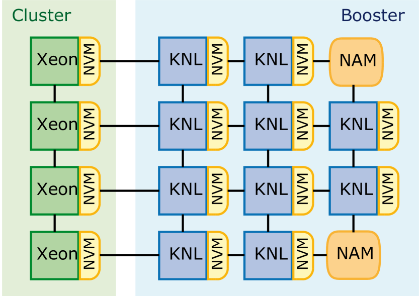
The Booster is attached to a standard HPC Cluster via a high-speed network. This connection, together with a uniform software stack running over both parts of the machine (see section III), enables Cluster and Booster acting together as a unified system. This opens up new prospects for application developers, who have full freedom to decide how they distribute their codes over the system. For example, code sections requiring high-single thread performance and/or large memory capacity will run best on the Cluster side, while well-parallelized and vectorised code parts will profit from the highly-scalable, energy efficient Booster. This is demonstrated in section IV, which presents measurements of an application that benefits from the Cluster-Booster approach.
In contrast to accelerated clusters, the Cluster-Booster concept poses no constraints on the combination of CPU and accelerator nodes that an application may select, since resources are reserved and allocated independently. This has two important effects: Firstly, each application can run on an optimal combination of resources and achieve maximum performance. Secondly, all resources can be put to good use by a system-wide resource manager. The latter allows combining the set of applications in a complementary way, increasing throughput and efficiency of use for the overall system. In the course of the DEEP project, major efforts were put into the extension of batch-system capabilities [5].
In DEEP-ER, additional memory components have been added to the Cluster-Booster system, including the NAM and the NVMe presented in section II-B.
II-B Prototype hardware configuration
The first prototype of the Cluster-Booster concept was designed and built in the course of the DEEP project [1]. The DEEP prototype consisted of 128 Cluster nodes (Intel Xeon, Sandy Bridge generation), and 384 Booster nodes (Intel Xeon Phi, Knights Corner - KNC generation). The different network technologies on Cluster (InfiniBand) and Booster (EXTOLL) made it necessary to use bridge-nodes between the two parts of the system. These where responsible both for transferring messages and for remote-booting the KNC nodes from the network, since these were not designed as stand-alone processors.
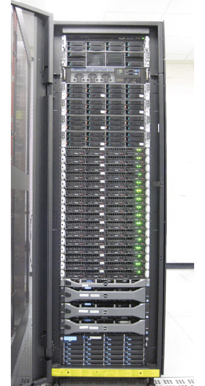
The successor – called the DEEP-ER prototype – (figure 2) is the second generation of the same architecture and was installed at JSC in 2016. It consists of 16 Cluster nodes and 8 Booster nodes; the configuration is detailed in table I. Given the size of the system and the strong focus of the DEEP-ER project on software development, the prototype construction was kept as simple as possible employing off-the-shelf, air-cooled hardware components. Cluster and Booster modules are integrated in a single, standard 19” rack, which also holds the storage system (one meta-data, two storage servers and 57 TB of storage on spinning disks).
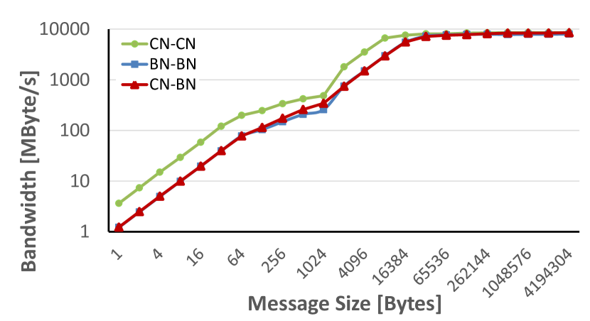
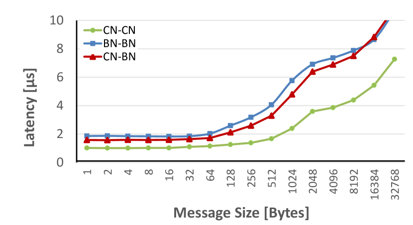
A uniform high-speed Tourmalet A3 EXTOLL fabric runs across Cluster and Booster, connecting them each internally, between each other, and to the central storage. Bandwidth and latency measured by end-to-end MPI communications between the different kinds of nodes are displayed in figure 3. For small message sizes communication is more efficient between the Cluster nodes due to the higher single thread performance of the Intel Xeon processors, compared to KNL. For large messages communication performance between all kinds of nodes is limited by fabric bandwidth.
| Feature | Cluster | Booster |
|---|---|---|
| Processor | Intel Xeon E5-2680 v3 | Intel Xeon Phi 7210 |
| Microarchitecture | Haswell | Knights Landing (KNL) |
| Sockets per node | 2 | 1 |
| Cores per node | 24 | 64 |
| Threads per node | 48 | 256 |
| Frequency | 2.5 GHz | 1.3 GHz |
| Memory (RAM) | 128 GB | 16 GB – MCDRAM |
| 96 GB – DDR4 | ||
| NVMe capacity | 400 GB | 400 GB |
| Interconnect | EXTOLL Tourmalet A3 | EXTOLL Tourmalet A3 |
| Max. link bandwidth | 100 Gbit/s | 100 Gbit/s |
| MPI latency111Note: The larger MPI latency on the Booster is due to the lower single thread performance of the Xeon Phi processor. It results from its different micro-architecture in combination with the reduced clock frequency compared to standard Xeon processors. | 1.0 s | 1.8 s |
| Node count | 16 | 8 |
| Peak performance | 16 TFlop/s | 20 TFlop/s |
The DEEP-ER prototype is enhanced by advanced memory technologies. A multi-level memory hierarchy has been built providing a total memory capacity of 8 TBytes. This enables the implementation of innovative I/O and resiliency techniques.
Each node of the DEEP-ER prototype (in both Cluster and Booster) features a non-volatile memory (NVM) device for efficient buffering of I/O and checkpointing. The chosen technology is Intel’s DC P3700 NVMe device, an replacement for SSD with 400 GByte capacity that provides high speed, non-volatile local memory, directly attached to the node via 4 lanes of PCIe gen3. NVMe is a new standard providing APIs and interfaces for this direct connection in the server market. On the long run, it aims at replacing today’s standard interfaces like SATA.
DEEP-ER has also introduced an innovative memory concept: the network attached memory (NAM) [6]. It combines Hybrid Memory Cube (HMC) devices with a state-of-the-art Xilinx Virtex 7 FPGA and exploits the remote DMA capabilities of the EXTOLL fabric. The latter enables access to remote memory resources without the intervention of an active component (as a CPU) on the remote side. In this way a high-speed memory device is created, which is directly attached to the EXTOLL fabric and therefore globally accessible by all nodes in the system.
The DEEP-ER prototype holds two NAM devices with a capacity of 2 GBytes each. This relatively small size is due to current HMC technology limitations. Future implementations potentially increase capacities and may trigger a rethinking of memory architectures for HPC and data analytics. In fact, the NAM concept is being further investigated by the successor project DEEP-EST.
III Software Environment
The guiding principle in the development of software for the Cluster-Booster concept has been to stick, as much as possible, to standards and well established APIs. The specific software features required to operate Cluster and Booster together as a single system are implemented in the lower layers of the software stack and are as transparent as possible to application developers. Thus, they experience the same software environment as on any other current HPC system and do not have to deal with the underlying hardware complexity. Furthermore, their codes stay portable and keep the capability to run out-of-the-box on this new kind of platform as well as on any other HPC system. Thus, application developers are not required to maintain yet another branch of their application’s source-code but just have to add corresponding pragmas.
III-A Programming Environment
The ParaStation MPI library has been specifically optimized to efficiently run within both, Cluster and Booster, and across them. In particular, MPI programs can run solely on the Cluster (without employing any Booster node), solely on the Booster (without using any Cluster node), or run distributed among both kinds of nodes. For the latter case, enhancements have been done in ParaStation implementing a heterogeneous, global MPI by exploiting semantic concepts long existing in the MPI-standard. In particular, the MPI-2 function MPI_Comm_spawn realises the offloading mechanism, which allows to spawn groups of processes from Cluster to Booster (or vice-versa). At the same time the global MPI provides an efficient way of exchanging data between the two parts of the system [3].
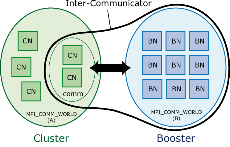
As sketched in figure 4, MPI_Comm_spawn is a collective operation performed by a (sub-)set of application processes running on either Cluster or Booster. The call requires as input the name of the binary to run and the number of processes to be started. It returns an inter-communicator, providing a connection handle to the children. Each child calls then MPI_Init, as usual, and gets access to the other end of the inter-communicator via MPI_Get_parent. Both parts of the applications – the original main part and the offloaded part – have their own MPI_COMM_WORLDs providing full MPI functionality on either side, and are connected to each other via inter-communicators.
III-B OmpSs abstraction layer
For a programmer, directly employing the MPI_Comm_spawn functionality requires coordinating and managing two or more sets of parallel MPI processes. This includes explicitly exchanging the necessary data between both sides of the system. This approach may become cumbersome for large and complex applications. To reduce the porting effort, an abstraction layer employing the global MPI has been implemented already in the DEEP project. It enables application developers to offload large, complex tasks by simply annotating via pragmas these parts of their code that shall run on a different part of the system.
This abstraction layer is based on the OmpSs data-flow programming model [7, 8]: an OpenMP 4.0-like environment exploiting task-level parallelism and supporting asynchronicity, heterogeneity and data movement. With OmpSs, an application’s code is annotated using OpenMP-like pragmas that indicate data dependencies between the different parts of the program. Taking these dependencies into account, the OmpSs runtime decides on the sequence of tasks and whether concurrent execution is allowed, creating a task dependency graph at run-time. All this information is used to schedule the tasks on the available hardware resources.
In order to support the DEEP offloading functionality OmpSs has been extended by an additional pragma to indicate the offload of a large compute-task including communication from Cluster to Booster, or vice-versa [9]. The pragma also holds information on data dependency and by this means it enables the OmpSs source-to-source compiler to insert all necessary MPI calls and to pass the resulting sources to the native tool-chain of the specific part of the system creating the binaries to be executed.
III-C I/O
The non-volatile memory of the DEEP-ER prototype (see II-B) is used as the foundation of a scalable I/O infrastructure. The resulting I/O software platform combines the parallel I/O library SIONlib [10] with the parallel file system BeeGFS [11]. Together, they enable the efficient and transparent use of the underlying hardware and provide the functionality and performance required by data-intensive applications and multi-level checkpointing-restart techniques.
The I/O library SIONlib acts as a concentration-layer enabling applications utilizing task-local I/O to efficiently use the underlying parallel file system. SIONlib bundles all data locally generated by applications, and stores it into one or very few large files, that the file system can easily manage. Furthermore, in DEEP-ER SIONlib bridges between the I/O and resiliency components of the software stack. It is used to copy local checkpoints into the NVM of a companion (buddy) node for redundancy, and to efficiently store checkpoint-data in the global file system. Both functions work in combination with the scalable checkpointing/restart library SCR (see section III-D).
The file system utilized in DEEP-ER is BeeGFS. It provides a solid, common basis for high-performance, parallel I/O operations. Advanced functionalities, such as a local cache layer in the file system, have been added to BeeGFS during the DEEP-ER project. The cache domain – based on BeeGFS on demand (BeeOND) [12] – stores data in fast node-local non-volatile memory devices and can be used in a synchronous or asynchronous mode. This speeds up the applications’ I/O operations and reduces the frequency of accesses to the global storage, increasing the overall scalability of the file system. The corresponding results will be discussed in detail in an up-coming article [13].
III-D Resiliency
The DEEP-ER project has adopted an improved user-level application checkpoint-restart approach, combining it with a task-based resiliency strategy.
The Open Source Scalable Checkpoint-Restart library (SCR) offers a flexible interface for applications to perform checkpoints and to restart from them in case of failure [14]. The user only needs to call SCR and indicate the data required by the application to restart execution. This library keeps a database of checkpoints and their locations in preparation for eventual re-initialization. In DEEP-ER, SCR has been extended to decide where and how often checkpoints are performed, based on a failure model of the DEEP-ER prototype.
The OmpSs programming model has been also extended by three new resiliency features. Input data of the OmpSs tasks can be saved into main memory before starting them, such that they can be restarted in case of failure. Alternatively, the input dependencies of a task can be used by OmpSs to fast-forward a re-started application to the latest check-point. Tasks offloaded from Cluster to Booster (or vice-versa) can also be restarted without loosing the work that has been performed in parallel by other OmpSs tasks.
IV Application results
Several real-world HPC applications have been used to steer and evaluate the design of the hardware and software developments in the DEEP projects. To properly represent the typically broad user portfolio of large-scale computer centres, the chosen co-design applications come from a wide range of scientific areas, including astrophysics, neuroscience, seismic imaging, climate science, computational fluid dynamics, molecular dynamics, etc.
The role of these applications in the project is two-fold: on the one hand, their requirements have provided co-design input to fix the characteristics of hardware and software components; on the other hand, the codes have evaluated the project developments by running different uses cases on the DEEP-ER prototype.
This paper focuses on the distribution of an application over both parts of the Cluster-Booster architecture, tested with the Space Weather application xPic. This code has been chosen for two reasons: it displays best the effect of partitioning an application between Cluster and Booster, and it is the code with which the most exhaustive benchmark-tests of this scenario have been performed until now. Other applications tested on the DEEP-ER prototype are of rather monolithic nature, meaning that they run either on the Cluster or the Booster, alone. Further heterogeneous simulation-workflows are being adapted to the concept in the recently started DEEP-EST project. Thorough experimental results will be presented in future publications.
IV-A Application description and structure
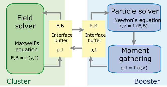
xPic is a Particle-in-Cell (PIC) simulation code from KU Leuven (Katholieke Universiteit Leuven) to forecast space weather events with the potential to harm spacecraft electronics, disturb GPS signals, or even damage the electrical infrastructure on Earth. It simulates the plasma produced in solar eruptions using the Implicit Moment Method [15]. Like most PIC codes, xPic consists of two parts, a particle solver and a field solver. The particle solver calculates the motion of charged particles in response to the electromagnetic field and collects statistical information about their charge density, velocity distribution and the corresponding electric current (called moment gathering); the field solver computes the electromagnetic field evolution in response to the particle movement. The workflow of xPic is presented in figure 5. Here, the color-coding employed along the paper has been kept: code-parts best suited for the Cluster are marked in green, while those in blue fit best on the Booster side of the DEEP-ER prototype.
IV-B Distributing an application between Cluster and Booster
The applications tested in the DEEP-ER prototype employed two alternative approaches to take advantage of the Cluster-Booster system: (1) launching MPI processes in one of the modules and spawning children MPI processes on the second module (see section III-A); and (2) using OmpSs pragmas to offload computing zones from the Cluster to the Booster (section III-B). The developers of the xPic code explored both approaches at the beginning of the DEEP project but finally decided to go for the first of them, due to their personal larger experience in MPI programming. The xPic code has then been divided in a particle solver that runs on Booster nodes and a field solver that runs on Cluster nodes. The application can also run in traditional architectures, by executing particle and field solver on the same kind of nodes.
The listing 1 in figure 6 shows the main loop of xPic in its original configuration. The field and particle solvers are labelled fld and pcl respectively. The solver calculates the electric (E) and magnetic (B) fields, while the particle solver performs the particle movement and the moment gathering. The functions cpyFromArr and cpyToArr move information between the solvers and the interface buffer shown in figure 5.
In the Cluster-Booster mode, the main loop is divided into two files, one containing the Cluster routines, and the second containing the Booster routines. In practice, the developer creates two copies of the main file and erases the fld calls in the Booster copy, and the pcl calls in the Cluster copy. Finally, after each cpy call, data is moved between the two solvers.
Figure 6 show the original main loop, together with the newly defined main loops for Cluster (listing 2) and Booster (listing 3). Differences are highlighted in green for the Cluster parts, and in blue for the Booster parts.
The functions ClusterToBooster and BoosterToCluster perform the MPI communications between the two modules. These are non blocking, and allow to overlap with non critical operations, like the computations of particle and field energy, the post-processing of data, and writing output files. Communications are performed using the INTERCOMM communicator created at the initialisation of the code with the MPI_Comm_spawn routine. Listing 4 shows how the function BoosterToCluster() uses these MPI communications.
The compilation script generates two executables, one containing the __BOOSTER__ code and the second containing the __CLUSTER__ code. At launch time, the execution script calls the Booster code, and this in turn performs a spawn with the name of the Cluster executable. ParaStation and the scheduler detect this call and distribute the child binaries in the correct locations in the Cluster.
IV-C Benchmarking results
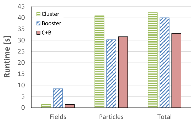
Figure 7 illustrates how the application xPic profits from distributing its two solvers (fields and particles) over the Cluster-Booster architecture described in section II-A. The results in this figure have been obtained using single Cluster and Booster nodes. Each solver uses a hybrid MPI+OpenMP code. The experimental setup is summarized in table II. In this case, running only on the Cluster means executing the particle solver on one Cluster node first and, once finished, using the same node for the field solver. The total execution time is the sum of the time employed by both solvers. The same applies to the case that uses only one Booster node. The Cluster-Booster mode (labelled C+B) runs the field solver on one Cluster node and the particle solver on one Booster node. The total execution time is here the sum of both parts and includes the overhead due to the MPI communication between them.
| Number of cells per node | 4096 |
|---|---|
| Number of particles per cell | 2048 |
| Compilation flags | -openmp, -mavx (Cluster), |
| -xMIC-AVX512 (Booster) |
The field solver matches best to the Cluster side, since this code-part is not highly parallel and requires substantial and frequent global communication. Accordingly, running the field solver on the Cluster (Haswell processors) is 6 faster than on the Booster (KNL processors). The highly parallel particle solver, on the other hand, moves billions of particles independently with almost no long-range communication. It turns out to be naturally suited to the Booster, where it runs about 1.35 faster than on the Cluster. Point-to-point communication is done between the field solver and particle solver (i.e. between Cluster and Booster) and constitutes only a small fraction (3% to 4% overhead per solver) of the total application communication.
Thus, the Cluster-Booster architecture allows matching the intrinsic structure of xPic to the hardware, i.e. running the field solver on the Cluster and the particle solver on the Booster. This distributed mode results in a 1.28 performance gain of the overall application, when compared to running the full code using only the Cluster. Comparing to an execution on the Booster alone, still a 1.21 performance gain of the Cluster-Booster (C+B) mode is achieved.
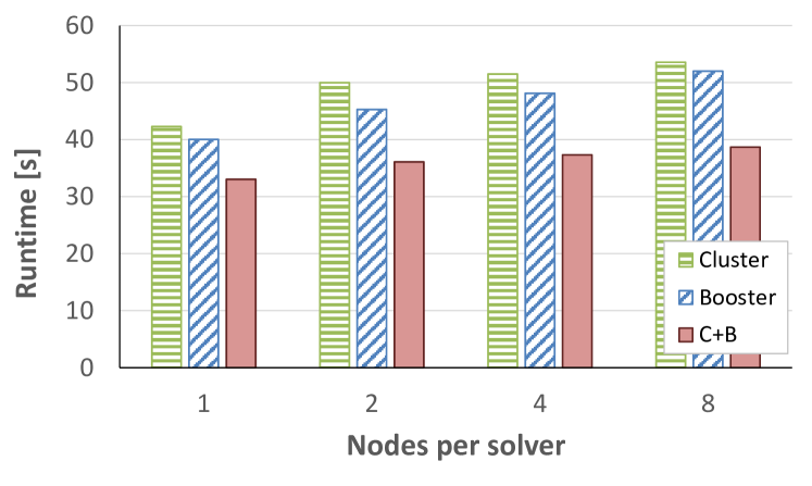
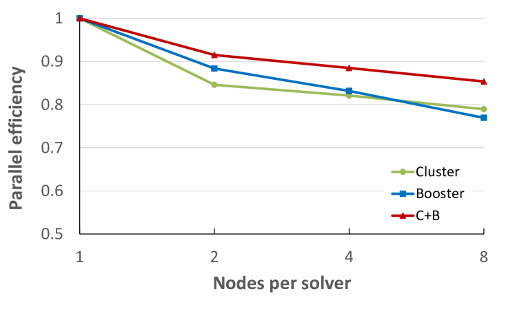
Scaling results for the three scenarios (only Cluster, only Booster, and Cluster-Booster mode) are presented in figure 8. The plots indicate that the performance gain of the C+B mode increases with the number of nodes. In the largest experiment possible on the DEEP-ER prototype (8 nodes), the distributed code runs 1.38 faster than using only the Cluster, and 1.34 faster than on the Booster alone. The C+B mode also achieves a better parallel efficiency (85%) than using the Cluster (79%) and Booster (77%) as stand-alone systems.
V Related work
This paper presents a different approach for the integration of heterogeneous resources within a HPC system. In fact, the actual idea is similar to the concept behind the development of the Quadrics Supercomputing World’s PQE 2000 system in the late 1990s[16]. Here the role of the Cluster as a more general purpose system was filled by a Meiko CS2 system utilizing SPARC processors and a proprietary interconnect build by Meiko. The part now named Booster was planned to be realized by a highly scalable APE Mille MPP system that was based on the APE series of machines originally designed for lattice QCD calculations. Nevertheless, at that time the idea did not make it to the market.
The original Cluster-Booster prototype of the DEEP project was challenging to realize since the first generation of Intel Xeon Phi processors were not designed to run as stand-alone processors. With the advent of Xeon Phi processors of the KNL generation also major hardware vendors like Cray offer systems that integrate Intel Xeon and Intel Xeon Phi processors into a single system. Examples for larger systems of this type are the Cori system at NERSC [17] based on Cray’s XC40 series or the Trinity system at LANL [18] based on Cray XC30. However, until now there is no indication that these systems will be used in the same fashion that is presented in this paper, i.e. by running applications across both type of processor architectures at the same time, utilizing MPI_Comm_spawn or similar calls in the MPI standard. In fact, MPI_Comm_spawn was not supported by Cray’s MPI until recently.
In a more general sense the integration of heterogeneous resources into a single system is available in many large-scale HPC system. They might have large memory nodes in order to support applications with the need for larger amounts of memory, although those applications are usually restricted to a single class of nodes alone. More in the sense of the approach presented in this paper are visualization nodes within a large scale supercomputer used for online visualization. Here both classes of nodes are used at the same time, one for running the actual application, the other in order to tap data from the running simulation and to derive graphical representation of these data. Nevertheless, in both cases the heterogeneity of the nodes is restricted to a different amount of memory or additional hardware like GPUs but typically leaving the processor architecture untouched. Furthermore there is no spawning of additional processes via MPI_Comm_spawn. Instead, communication between the different application parts (simulation and visualization) is done by different measures.
For the concept of NAM a similar approach is realized by the RAM Area Network developed by Kove in its xpd appliance [19]. While NAM directly attaches HMC memory to the EXTOLL interconnect, Kove utilizes standard DRAM DIMMs and multiple InfiniBand HCA in order to realize larger capacity and higher bandwidth. The main difference between the two concepts is that the xpd appliance still requires a standard processor while for the NAM all functionality is integrated in a single FPGA.
VI Conclusions and Outlook
The DEEP projects have introduced several hardware and software innovations to improve the capabilities of today’s HPC systems, addressing several of the Exascale challenges. In particular, an innovative architecture concept has been introduced, which provides the applications with full flexibility on how to exploit different kinds of computing resources.
The Cluster-Booster architecture integrates heterogeneous resources at the system level, instead of the node level. The Booster (a cluster of many-core processors or accelerators) is attached to a Cluster (a system of general purpose processors) via a high-speed network. Application developers have full freedom to decide how they distribute their codes over the system and can match the requirements of their different code parts to the available hardware.
The performance improvement that this approach can provide to real-world applications has been demonstrated by the Space Weather code xPic. It was able to achieve its results in shorter time, and with a better parallel efficiency when distributing the code over Cluster and Booster, than when running separately on any of them.
It is important to mention that these results have been achieved without compromising the portability of the code, which regularly runs on other “standard” HPC systems. This has been achieved by using standard interfaces and software components.
The Cluster-Booster architecture, which was first prototyped in the DEEP projects, has gone into production in the meantime. The JURECA Cluster, running at the Jülich Supercomputing Center (JSC) in Germany since 2015 [20], has been recently accompanied by a KNL-based, 5 PFlop/s Booster, which is planned to become available to users in Q1/2018.
The DEEP and DEEP-ER projects have been completed and successfully evaluated by external reviewers. Building on their results, the successor project (DEEP-EST) currently generalises the Cluster-Booster concept to create a Modular Supercomputing architecture [4]. It combines any number of compute modules (Cluster and Booster are two such modules) into a unified computing platform. Each compute module is a cluster of a potentially large size, tailored to the specific needs of a class of applications. A high-speed interconnect between the modules and a uniform software stack across them enables codes and work-flows to run distributed over the whole machine, matching their specific needs to the available computing resources. One of the most important contributions expected from DEEP-EST is the further enhancement of resource management software and scheduling strategies to deal with any number of compute modules. To demonstrate its capabilities, a hardware prototype consisting of three modules will be built. It shall cover the needs of both HPC and high performance data analytics (HPDA) workloads.
In parallel to DEEP-EST, JSC is already starting the implementation of the Modular Supercomputing architecture in a large-scale production system. The first module of the new Modular Supercomputing infrastructure will be a general purpose cluster, to be deployed in Q2/2018. Its Booster component is planned for 2019/2020. Further modules will be added in the future, always aiming at optimally addressing the needs of the wide spectrum of user communities and applications running at the HPC centre.
Acknowledgements
The authors would like to thank all the people and partners involved in the DEEP consortia for their engagement and strong commitment towards the DEEP projects, which led to several of the results described in this paper. Special gratitude goes to M. Nüssle from EXTOLL GmbH for the MPI benchmarks on the Tourmalet network (figure 3).
Part of the research presented here has received funding from the European Community’s Seventh Framework Programme (FP7/2007-2013) under Grant Agreement n∘ 287530 (DEEP) and 610476 (DEEP-ER), and from the Horizon 2020 Programme (H2020-FETHPC) under Grant Agreement n∘ 754304 (DEEP-EST). The present publication reflects only the authors’ views. The European Commission is not liable for any use that might be made of the information contained therein.
References
- [1] (2018) The DEEP projects website. [Online]. Available: http://www.deep-projects.eu/
- [2] N. Eicker and T. Lippert, “An accelerated Cluster-Architecture for the Exascale,” in PARS ’11, PARS-Mitteilungen, Mitteilungen - Gesellschaft für Informatik e.V., Parallel-Algorithmen und Rechnerstrukturen, ISSN 0177-0454, Nr. 28, Oktober 2011 (Workshop 2011), 110 - 119, 2011, record converted from VDB: 12.11.2012. [Online]. Available: http://juser.fz-juelich.de/record/19212
- [3] N. Eicker, T. Lippert, T. Moschny, E. Suarez, and for the DEEP project, “The deep project: An alternative approach to heterogeneous cluster-computing in the many-core era,” Concurrency and Computation: Practice and Experience, vol. 28, no. 8, pp. 2394–2411, 2016, cpe.3562. [Online]. Available: http://dx.doi.org/10.1002/cpe.3562
- [4] E. Suarez, N. Eicker, and T. Lippert, “Supercomputer Evolution at JSC,” ser. Publication Series of the John von Neumann Institute for Computing (NIC) NIC Series, vol. 49, NIC Symposium 2018, Jülich (Germany), 22 Feb 2018 - 23 Feb 2018. Jülich: John von Neumann Institute for Computing, Feb 2018, pp. 1 – 12. [Online]. Available: http://juser.fz-juelich.de/record/844072
- [5] S. Prabhakaran, M. Neumann, S. Rinke, F. Wolf, A. Gupta, and L. V. Kale, “A batch system with efficient adaptive scheduling for malleable and evolving applications,” in Proceedings of the 2015 IEEE International Parallel and Distributed Processing Symposium, ser. IPDPS ’15. Washington, DC, USA: IEEE Computer Society, 2015, pp. 429–438. [Online]. Available: http://dx.doi.org/10.1109/IPDPS.2015.34
- [6] J. Schmidt, “Accelerating checkpoint/restart application performance in large-scale systems with network attached memory,” Ph.D. dissertation, Ruprecht-Karls University Heidelberg, Faculty for Mathematics and Computer Science, 2017. [Online]. Available: http://archiv.ub.uni-heidelberg.de/volltextserver/23800/1/dissertation_juri_schmidt_publish.pdf
- [7] A. Duran, E. Ayguadé, R. M. Badia, J. Labarta, L. Martinell, X. Martorell, and J. Planas, “Ompss: A proposal for programming heterogeneous multi-core architectures,” Parallel Processing Letters, vol. 21, no. 02, pp. 173–193, 2011.
- [8] (2018) Ompss website. [Online]. Available: https://pm.bsc.es/ompss
- [9] F. Sainz, J. Bellón, V. Beltran, and J. Labarta, “Collective offload for heterogeneous clusters,” in 2015 IEEE 22nd International Conference on High Performance Computing (HiPC), Dec 2015, pp. 376–385.
- [10] W. Frings, F. Wolf, and V. Petkov, “Scalable Massively Parallel I/O to Task-Local Files,” in Proceedings of the Conference on High Performance Computing Networking, Storage and Analysis, Portland, Oregon, November 14 - 20, 2009, SC’09, SESSION: Technical papers, Article No. 17, New York, ACM, 2009.ISBN 978-1-60558-744-8. - S. 1 - 11, 2009, record converted from VDB: 12.11.2012. [Online]. Available: http://juser.fz-juelich.de/record/4447
- [11] (2018) BeeGFS website. [Online]. Available: https://www.beegfs.io/content/
- [12] (2018) BeeGFS On Demand website. [Online]. Available: https://www.beegfs.io/wiki/BeeOND
- [13] A. Kreuzer, J. Amaya, N. Eicker, R. Léger, and E. Suarez, “The DEEP-ER project: I/O and resiliency extensions for the Cluster-Booster architecture,” 2018 IEEE 20th International Conference on High Performance Computing and Communications, Exeter (United Kingdom), 28 Jun 2018 - 30 Jun 2018. IEEE, Jun 2018, pp. 109 – 116. [Online]. Available: http://juser.fz-juelich.de/record/860444
- [14] A. Moody, G. Bronevetsky, K. Mohror, and B. R. d. Supinski, “Design, modeling, and evaluation of a scalable multi-level checkpointing system,” in Proceedings of the 2010 ACM/IEEE International Conference for High Performance Computing, Networking, Storage and Analysis, ser. SC ’10. Washington, DC, USA: IEEE Computer Society, 2010, pp. 1–11. [Online]. Available: https://doi.org/10.1109/SC.2010.18
- [15] S. Markidis, G. Lapenta, and Rizwan-uddin, “Multi-scale simulations of plasma with ipic3d,” Mathematics and Computers in Simulation, vol. 80, no. 7, pp. 1509 – 1519, 2010, multiscale modeling of moving interfaces in materials. [Online]. Available: http://www.sciencedirect.com/science/article/pii/S0378475409002444
- [16] P. Palazzari, L. Arrcipiani, M. Celino, R. Guadagni, A. Marongiu, A. Mathis, P. Novelli, and V. Rosato, “Heterogeneity as key feature of high performance computing: the pqe1 prototype,” in Proceedings 9th Heterogeneous Computing Workshop (HCW 2000) (Cat. No.PR00556), 2000, pp. 17–30.
- [17] (2018) Cori website. [Online]. Available: http://www.nersc.gov/users/computational-systems/cori/
- [18] (2018) Trinity website. [Online]. Available: http://www.lanl.gov/projects/trinity/
- [19] (2018) Kove website. [Online]. Available: http://kove.net/xpd
- [20] D. Krause and P. Thörnig, “JURECA: General-purpose supercomputer at Jülich Supercomputing Centre,” Journal of large-scale research facilities, vol. 2, p. A62, 2016. [Online]. Available: http://juser.fz-juelich.de/record/807073