Material slow and fast light in a zero-dispersion configuration
Abstract
We study the propagation of light pulses in an absorbing medium when the frequency of their carrier coincides with a zero of the refractive index dispersion. Although slow light and, a fortiori, fast light are not expected in such conditions, we show that both can be obtained by selecting particular phase-components of the transmitted field. Analytical expressions of the resulting signals are obtained by a procedure of periodic continuation of the incident pulse and a proof of principle of the predicted phenomena is performed by means of a very simple electrical network, the transfer function of which mimics that of the medium.
I Introduction
The one-dimensional propagation of coherent light pulses with a slowly varying envelope through a linear medium is usually analyzed by means of the group velocity bo02 . At the optical frequency it reads where is the light velocity in vacuum, is the refractive index and its derivative is the refractive index dispersion. When the group velocity and the medium transmission are both constant over the whole pulse spectrum, the envelope travels undistorted at the velocity where is the pulse carrier frequency and is a short-hand notation of for . When the above-mentioned double condition is not fulfilled, group velocity dispersion and transmission variation over the pulse spectrum result in a pulse reshaping.
The refractive index dispersion can take very large positive or negative values when the carrier frequency of the pulses is equal or close to the frequency of a narrow and well-marked dip or peak of the medium transmission. When (normal dispersion), the group velocity is then very small compared to the phase velocity (slow light regime) while it becomes very large or even negative (fast last regime) when (anomalous dispersion). The principle of causality implies that the two regimes can be obtained with a same medium, depending on the probe frequency bol93 . We examine in the present article what occurs when is such that (zero-dispersion configuration). Neither slow light nor fast light are expected in this case. We will however show that both can be observed by post-selecting particular phase components of the transmitted field, in analogy with the experiments involving post-selection of the field polarization so03 ; bru4 ; bi08 ; ma16 . We specifically consider the reference case of a medium with a narrow absorption line. Convincing demonstrations of slow light gri73 ; si09 and fast light chu82 ; se85 ; ta03 ; ke12 ; je16 have been performed with this system. The arrangement of our paper is as follows. In Section II, we give the transfer functions for the electric field and for its relevant phase components. The envelopes of the corresponding transmitted pulses are determined in Section III and we give in Section IV a proof of principle of the predicted phenomena by means of a very simple electrical network. We conclude in Section V by summarizing our main results.
II TRANSFER FUNCTIONS OF THE MEDIUM
Slow or fast light effects can be directly evidenced by comparing the pulse transmitted by the medium (probe) to that which would be transmitted in vacuum (reference). The transfer functions linking the Fourier transforms of the corresponding fields to that of the incident field read, respectively, and , where is the complex refractive index of the medium and its thickness pa87 . In the time domain, the reference field is simply delayed by the luminal transit time and this naturally leads to use times retarded by to describe the transmitted fields. In this retarded time picture the transfer function for the probe becomes
| (1) |
and the reference field is equal to the incident field in real time.
For the sake of simplicity, we consider a dilute medium with a Lorentzian absorption line of half width at half maximum very small compared to the resonance frequency (narrow resonance limit). Under these conditions, the complex susceptibility of the medium is such that and, in SI units, the complex refractivity is reduced to
| (2) |
In addition, the susceptibility is only significant when . For , the classical Lorentz model bo02 ; ma96 and the semi-classical model of two-levels atoms al87 ; bo92 both lead to a relation of the form
| (3) |
with . Eqs. (1, 2, 3) finally yield
| (4) |
where naturally appears as the medium absorption coefficient on resonance for the amplitude. By denoting the phase of , the group advance (the opposite of the group delay) is given by the relation pa87 and Eq.4 yields
| (5) |
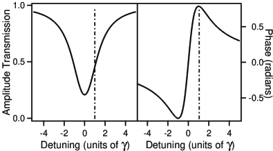
where is the detuning of the pulse carrier frequency from resonance. The group advance attains its maximum for , is positive (fast light regime) when and negative (slow light regime) when . It cancels when . We will consider in the following the case where . Quite similar results are obtained when . Figure 1 shows the amplitude transmission and phase as functions of the detuning in the reference case . The vertical dash-dotted line indicates the carrier frequency considered in the following.
The transfer function for the pulse envelope is derived from Eq.(4) by passing in a frame rotating at the frequency al87 . We get
| (6) |
where with . On exact resonance (), , where the asterisk indicates complex conjugate. The corresponding impulse response , inverse Fourier transform of pa87 , is then real cri70 ; ma18 . If the envelope of the incident pulse is real (unchirped pulse) as assumed in the following, the envelope of the transmitted pulse will be also real or, otherwise said, probe and reference fields will be in phase. In addition the relation implies that the amplitude transmission and the phase of are, respectively, even and odd functions of . As discussed in ma18 , the group advance can then be identified to the advance of the center-of-gravity (COG) of over that of while is the ratio of the two envelopes areas ma18 . These results hold whatever the pulse distortion is.
In the zero-dispersion configuration (), and the impulse response is complex. The envelope of the transmitted pulse is also complex. Its real part and imaginary part are then the envelopes of the components of the probe field, respectively, in phase (I) and in quadrature (Q) with the reference field. The impulse responses linking the envelopes of these two components to that of the reference pulse read:
| (7) |
| (8) |
Coming back in the frequency domain, we get the corresponding transfer functions
| (9) |
| (10) |
These transfer functions are closely related to those encountered in Ref.ma16 where the post-selection was made on the field polarization. As in the resonant case, and the modulus and phase are, respectively, even and odd functions of . As made in the resonant case, we derive from Eqs.(6,9, 10) the advance of the COG of over that of and the ratio of its algebraic area over that of . We get
| (11) |
| (12) |
| (13) |
| (14) |
The most significant results are obtained when and are both minimum-phase-shift functions. This requires that all the zeroes of their continuation in the complex plane have a positive imaginary part pa87 . It is easily shown that this condition is met when . It then results from Eqs.(11, 13) that the COG of is advanced (fast light regime) while that of is delayed (slow light regime). We additionally remark that the transmissions and are, respectively, minimal and maximal for .
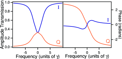
Figure 2 illustrates the previous points in the reference case already considered in Fig.1. We are then in the remarkable situation where and . This means that the COG of and are shifted by the same amount in absolute value and that their algebraic area are equal.
A special attention will be paid in the following on fast light which suffers from the most severe restrictions. Eq.(11) might lead to expect that advances as large as wanted could be obtained for . It is worth remarking that this equation only gives the advance of the pulse COG and that the corresponding transmission cancels. Anyway, obtaining large absolute advances is not an aim per se and the challenge in fast light experiments is to attain ratios of the advances over the pulse duration as large as possible with moderate distortion. The practical limitations to these fractional advances are examined in the following section.
III ENVELOPES OF THE INCIDENT AND TRANSMITTED PULSES
We consider an incident pulse of carrier frequency and of envelope
| (15) |
where designates the rectangle function equal to for and elsewhere. This pulse is very close to the Gaussian pulse usually considered in the literature. It has a full width at half maximum (taken as time unit in the following) and a strictly finite overall duration . We exploit this point by continuing the envelope at every time by the periodic signal
| (16) |
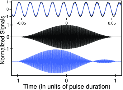
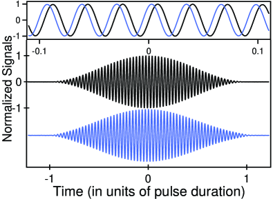
contains only three frequencies, namely and with . As shows Fig.3, the signals obtained by substituting to reproduce very well the main features of the exact envelopes obtained by fast Fourier transform (FFT). We get:
| (17) |
has a maximum of amplitude in advance over that of the reference pulse by . The corresponding fractional advances read
| (18) |
The advances of the maximum have the same sign that the corresponding group advances ( , ). Since , the amplitude of the advanced signal is larger than its asymptotic value when (), the opposite occurring for the amplitude of the delayed signal []. Equation (17) also enables us to determine the full duration at half maximum and of both signals. They read
| (19) |
with (pulse narrowing) and (pulse broadening). All these results are consistent with those expected for systems having a dip or a peak of transmission.
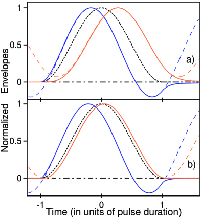
In agreement with relativistic causality, both phase components start at the same time that the incident pulse in our retarded time picture (Fig.3). As soon as it has a significant amplitude, the component is simply broadened and the (negative) advance of its maximum is generally close to the group advance . The behaviour of the in-phase component is richer. The pulse distortion of is manifested in a narrowing (as already mentioned) and, moreover, in the appearance of a secondary lobe ma18 . The latter is also well reproduced by the periodic model (Fig.3). Quite generally, its maximum occurs at and its relative amplitude compared to that of the main lobe reads
| (20) |
When it is small compared to unity, constitutes a good indicator of the pulse distortion. The corresponding duration and peak-amplitude of given by the periodic model read:
| (21) |
| (22) |
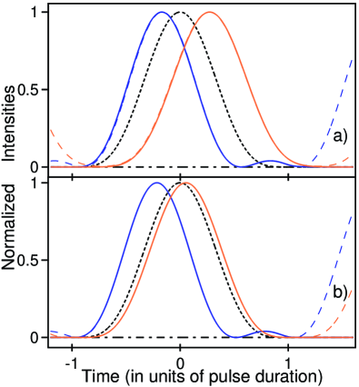
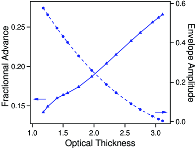
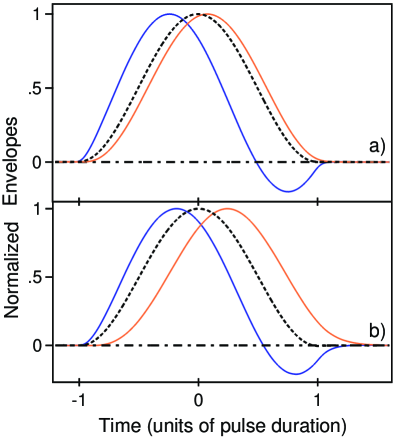
The envelopes shown Fig.3a and Fig.3b have been obtained, respectively, for (reference case) and for . In both cases, the pulse duration has been chosen such that . As illustrated Fig.4, the distortion of the corresponding intensity profiles (currently considered in optics) is quite moderate and the fractional advances are times larger than those of the envelopes. We note in particular that the advanced intensity profiles compare favourably with those observed in the reference experiments involving a gain-doublet medium ste03 .
For a given distortion, relativistic causality imposes severe limitations to the fractional advance of . As for every fast light system, the larger is the dynamics of the system transmission, the larger is the fractional advance ma05 . In the present case, the transmission dynamics [maximum over minimum of ] is reduced to . Eq.(22) thus involves that the amplitude and the fractional delay evolve in opposite directions as functions of the optical thickness . Figure 5 shows the results obtained for in a broad domain of variation of . In the reference case (conditions of Fig.3a), we get and while and when (conditions of Fig.3b). In the latter case, sufficient amplitude is conciliated with a fractional advance which is not far below its asymptotic value (, see below).
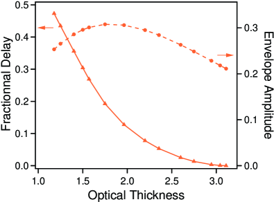
For the sake of completeness, we give Fig.6 the results obtained in the conditions of Fig.5 for the delayed envelope . The variations of its amplitude are moderate, while the fractional delay continuously decreases to when . We additionally mention that, correlatively, the pulse duration (the ratio ) regularly decreases (increases) to ( to ).
When , the pulse duration required to obtain a fixed distortion becomes very long. Denoting , we get at the leading order in
| (23) |
where . Putting this value in the transfer functions , we get, always at the leading order in , the following asymptotic expressions of the pulse advances and amplitudes
| (24) |
| (25) |
| (26) |
| (27) |
| (28) |
Eqs.(24, 25) shows that, strictly speaking, only when but the fractional advance is then very small. As for each fast light system, significant fractional advances are paid by some distortion. The previous results are quite consistent with those shown Figs.(5, 6) for , that is . For , we get in particular , , , and .
IV EXPERIMENTS WITH AN ELECTRICAL NETWORK
In the optical experiments, the information on the phase shift induced by the medium can be obtained by means of a frequency change translating both reference and probe fields in the radiofrequency domain che05 ; lee13 . The experiments are greatly simplified by working directly in this domain. As back as 1961, Rupprecht ru61 evidenced significant advances of the envelope of the pulse transmitted by a radiofrequency network with negative group delay (NGD). More recent demonstrations of advanced pulse-envelope can be found in mi98 ; ca03 ; si04 ; ra13 ; ra14 . However, as far as we know, the idea of phase post-selection to evidence NGD effects is absent in all these experiments.
Figure 7 shows the very simple four port network employed in our experiments.
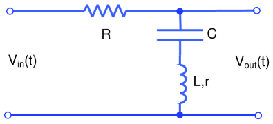
As the absorbing medium, it is purely passive. In the narrow resonance limit, the transfer function relating the Fourier transform of the output signal to that of the input signal reads
| (29) |
where (), and with . The general relation giving the group advance yields
| (30) |
where is the detuning of the pulse carrier frequency from resonance. As for the absorbing medium, the group advance is positive when , is negative when , cancels when and is maximum on resonance where it takes the simple form . The experimental transmission and phase obtained for , and are shown Fig.8.
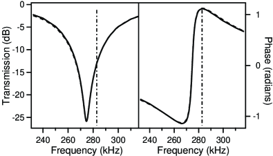
They are in excellent agreement with those derived from Eq.(29). Note, however, that the values of , and somewhat differ from those given below Eq.(29) which are obtained by considering ideal components without including the self-resonant behaviour of the capacitor and inductor si04 .
In the time-resolved experiments, we use a waveform generator (Agilent 33500B) delivering both the sinewave signal of frequency and the modulation signal. It is used in the burst mode (single-shot experiment). The signals and are sent on two channels of a numerical oscilloscope (Keysight InfiniiVision DSOX4024A) and both are acquired on 16000 points with a 10 bit vertical resolution. Figure 9 gives an example of signals obtained in the resonant case () with the parameters of Fig.8. As expected, the maximum of is significantly in advance over that of but the two signals are in phase.
On the other hand, Fig.10, obtained in the zero-dispersion configuration ( ), confirms that the advance is then negligible but that the two signals are not in phase.
The transfer functions , and for the envelopes in the zero-dispersion configuration () are derived from as those of the absorbing medium. For the electrical network reads
| (31) |
As in the absorbing medium case, the transfer functions and are deduced from by Eqs.(9,10). They yield in particular
| (32) |
| (33) |
| (34) |
| (35) |
For a given distortion , the upper limit of the fractional advance is again approached when , that is when the pulse amplitude . By calculations quite similar to those leading to Eqs.(23-28), we retrieve the upper limit ( for ) obtained in the absorbing medium case.
The post-selection of the in-phase and quadrature components of the output signal is experimentally performed as follows. The data collected by the numerical oscilloscope are treated by computer. In a first step, we generate a continuous sinewave, the frequency and phase of which coincide with those of the input signal .
This continuous sinewave is next multiplied by the output signal to deliver the envelope of the in-phase component (I), the harmonic at and the high frequency noise being eliminated by a finite impulse response (F.I.R.) filter. The used low pass filter (IGOR software Blackman 367) insures a rejection better than 70 dB for . The envelope of the quadrature component is similarly derived by using a continuous sinewave in quadrature with that used to obtain .
Figure 11 shows the envelopes and experimentally observed in the zero-dispersion configuration () in two representative cases. As it was made to obtain Fig.10 also as Figs.(3-6) for the absorbing medium, the durations of the incident pulse are chosen such that for the I-component. The envelopes shown Fig.11a are observed in the conditions of Fig.10. They are quite comparable to those obtained theoretically with an absorbing medium of optical thickness (see Fig.3b). In particular, the advance is significantly larger than the delay . On another hand, the amplitudes of the two components are such that and this explains why no secondary lobe is visible Fig.10 in the overall envelope . As a second example, Fig.11b shows the envelopes experimentally observed when and . In this case and are both close to unity and the envelopes are now comparable to those obtained in the case taken as reference for the absorbing medium (see Fig.3a). In case a) as in case b), the observed envelopes are in very good agreement with the envelopes derived by FFT by using the transfer function given Eq.(31). In addition, the advances, amplitudes and pulse durations are exactly determined by the periodic model with, in particular, and as predicted by Eqs.(21,22).
V CONCLUSION
The dilute medium with a narrow absorption line is a reference system for the observation of fast and slow light. Fast light is obtained when the carrier frequency of the incident pulse coincides or is close to resonance while slow light is observed when this frequency lies in the line wings. There are thus two intermediate carrier frequencies for which the group velocity equals that of the light in vacuum. Paradoxically enough, we have shown that, in such a case, fast and slow light can be simultaneously observed. This is achieved by post-selecting particular phase components of the transmitted field. Fast light is obtained by selecting the component in phase with that of a pulse travelling the same distance in vacuum while slow light is observed on the quadrature component. The general properties of fast and slow light are retrieved with this arrangement. A particular attention is paid to fast light to which the relativistic causality imposes the most severe constraints. As usual, evidencing significant fast light effects with moderate distortion requires large transmission dynamics of the medium and long incident pulses. Finally the theoretical results obtained in optics with an absorbing medium are experimentally reproduced by using a passive electrical network running in the radiofrequency range. We expect that our work will stimulate direct demonstrations in optics or microwave. In this purpose, we emphasize that the phase post-selection procedure introduced in the present article can be applied to different frequency configurations and systems.
Funding: Contrat de Plan Etat-Région (CPER), Photonics and Society Project (P4s) ; Agence Nationale de Recherche (ANR), LABEX CEMPI Project (ANR-11-LABX-0007).
Disclosures:The authors declare no conflicts of interest.
References
- (1) R.W. Boyd and D.J. Gauthier, "Slow and Fast light”, Prog. Opt. 43, Ch. 6 (2002).
- (2) E.L. Bolda, R.Y. Chiao, and J. Garrison, “Two theorems for the group velocity in dispersive media”, Phys. Rev. A 48, 3890-3894 (1993).
- (3) D.R. Solli, C.F. McCormik, C. Ropers, J.J. Morehead, R.Y. Chiao, and J.M. Hickmann, “Demonstration of Superluminal Effects in an Absorptionless, Nonreflective System”, Phys. Rev. Lett. 91, 143906 (2003).
- (4) N. Brunner, V. Scarani, M. Wegmüller, M. Legré, and N. Gisin, “Direct Measurement of Superluminal Group Velocity and Signal Velocity in an Optical Fiber”, Phys. Rev. Lett. 93, 203902 (2004).
- (5) P. Bianucci, C.R. Fitz, J.W. Robertson, G. S. Shvets, and C.K. Shi, “Observation of simultaneous fast and slow light”, Phys. Rev. A 77, 053816 (2008).
- (6) B. Macke and B. Ségard, “Simultaneous slow and fast light involving the Faraday effect”, Phys. Rev. A 94, 043801 (2016).
- (7) D. Grischkowsky, “Adiabatic following and slow optical pulse propagation in rubidium vapor”, Phys. Rev. A 7, 2096-2102 (1973).
- (8) P. Siddons, N.C. Bell, Y. Cai, C.S. Adams, and I.G. Hughes, “A gigahertz-bandwidth atomic probe based on the slow-light Faraday effect”, Nature Photonics 3, 225-229 (2009).
- (9) S. Chu and S. Wong, “Linear pulse propagation in an absorbing medium”, Phys. Rev. Lett. 48, 738-741 (1982).
- (10) B. Ségard and B. Macke, “Observation of negative velocity pulse propagation”, Phys. Lett. 109A, 213-216 (1985).
- (11) H. Tanaka, H. Niwa, K. Hayami, S. Furue, K. Nakayama, T. Kohmoto, M. Kunitomo, and Y. Fukuda, “Propagation of optical pulses in a resonantly absorbing medium: Observation of negative velocity in Rb vapour”, Phys. Rev. A 68, 053801 (2003).
- (12) J. Keaveney, I.G. Hughes, A. Sargsyan, and C.S. Adams, “Maximal refraction and superluminal propagation in a gaseous nanolayer”, Phys. Rev. Lett. 109, 233001 (2012).
- (13) S Jennewein, Y.R.P. Sortais, J.F. Greffet, and A. Browaeys, “Propagation of light through small clouds of cold interacting atoms”, Phys. Rev. A 94, 053828 (2016).
- (14) A. Papoulis, The Fourier integral and its applications (Mc Graw Hill, New York, 1987). As in this textbook, we use the sign conventions of the linear system theory which differ from those currently considered in optics. The final results obviously do not depend on the used convention.
- (15) M. May and A.M. Cazabat, Optique (Dunod, Paris 1996).
- (16) L. Allen and J.H. Eberly, Optical resonance and two-level atoms (Dover, New York 1987).
- (17) R.W. Boyd, Nonlinear Optics (Academic, San Diego 1992).
- (18) M.D. Crisp, “Propagation of Small-Area Pulses of Coherent Light through a Resonant Medium”, Phys. Rev. A 1, 1604-1611 (1970).
- (19) B. Macke and B. Ségard, "On-resonance material fast light”, Phys. Rev. A 97, 063830 (2018).
- (20) M.D. Stenner, D.J. Gauthier, and M. Neifeld, "The speed of light in a ’fast ligh’ optical medium", Nature (London) 425, 695-698 (2003).
- (21) B. Macke, B. Ségard, and F. Wielonsky, "Optimal superluminal systems", Phys. Rev. E 72, 035601(R) (2005).
- (22) Y.F. Chen, Y.C. Liu, Z.H. Tsai, S.H. Wang, and I.A. Yu, “Beat-note interferometer for direct phase measurement of photonic information”, Phys. Rev. A 72, 033812 (2005).
- (23) Y.S. Lee, H.J. Lee, and H.S. Moon, “Phase measurement of fast light pulse in electromagnetically induced absorption”, Opt. Express 21, 22464-22470 (2013).
- (24) W. Rupprecht, Lineare Netzwerke mit negativer Gruppenlaufzeit, Dissertation. (Technische Hochschule Karlsruhe, 1961).
- (25) M. W. Mitchell and R. Y. Chiao, “Causality and Negative Group Delays in a Simple Bandpass Amplifier”, Am. J. Phys 66, 14-19 (1998).
- (26) H. Cao, A. Dogariu, and L.J. Wang, “Negative Group Delay and Pulse Compression in Superluminal Pulse Propagation”, IEEE J. Sel. Top. Quantum Electron. 9, 52-58 (2003).
- (27) O. F. Siddiqui, S. J. Erickson, G. V. Eleftheriades, and M. Mojahedi, “Time-Domain Measurement of Negative Group Delay in Negative-Refractive-Index Transmission-Line Metamaterials”, IEEE Trans. Microw. Theory Techn. 52, 1449-1454 (2004).
- (28) B. Ravelo, “Methodology of elementary negative group delay active topologies identification”, IET Circuits Devices Syst. (CDS) 7, 105-113 (2013).
- (29) B. Ravelo, “Similitude between the NGD function and filter gain behaviours”, Int. J. Circ. Theor. Appl. 42, 1016-1032 (2014).