Quasi-Direct Drive for Low-Cost Compliant Robotic Manipulation
Abstract
Robots must cost less and be force-controlled to enable widespread, safe deployment in unconstrained human environments. We propose Quasi-Direct Drive actuation as a capable paradigm for robotic force-controlled manipulation in human environments at low-cost. Our prototype - Blue - is a human scale 7 Degree of Freedom arm with 2kg payload. Blue can cost less than $5000. We show that Blue has dynamic properties that meet or exceed the needs of human operators: the robot has a nominal position-control bandwidth of 7.5Hz and repeatability within 4mm. We demonstrate a Virtual Reality based interface that can be used as a method for telepresence and collecting robot training demonstrations. Manufacturability, scaling, and potential use-cases for the Blue system are also addressed. Videos and additional information can be found online at berkeleyopenarms.github.io.
I Introduction
I-A Problem Definition and User Needs
The future of robotic manipulation is in unconstrained environments such as warehouses, homes, hospitals, and urban landscapes. These robots must operate with dexterity and safety alongside people despite imperfect actuation, lapses in sensing, and unmodeled contacts. Unlike traditional position-controlled manipulators, force-controlled robots can robustly react to unpredicted interactions without incurring damage to the environment or the robot itself. We believe the current class of compliant manipulators are too expensive or lack sufficient performance to complete useful tasks in human environments. This paper presents a fully realized paradigm for a low-cost Quasi-Direct Drive (QDD) manipulator and discusses considerations taken for the design and manufacturing of this system.
Our design goals support recent trends in AI-based control methods. We believe these control methods can be more widely applied in human environments if force-controlled robots are made affordable.
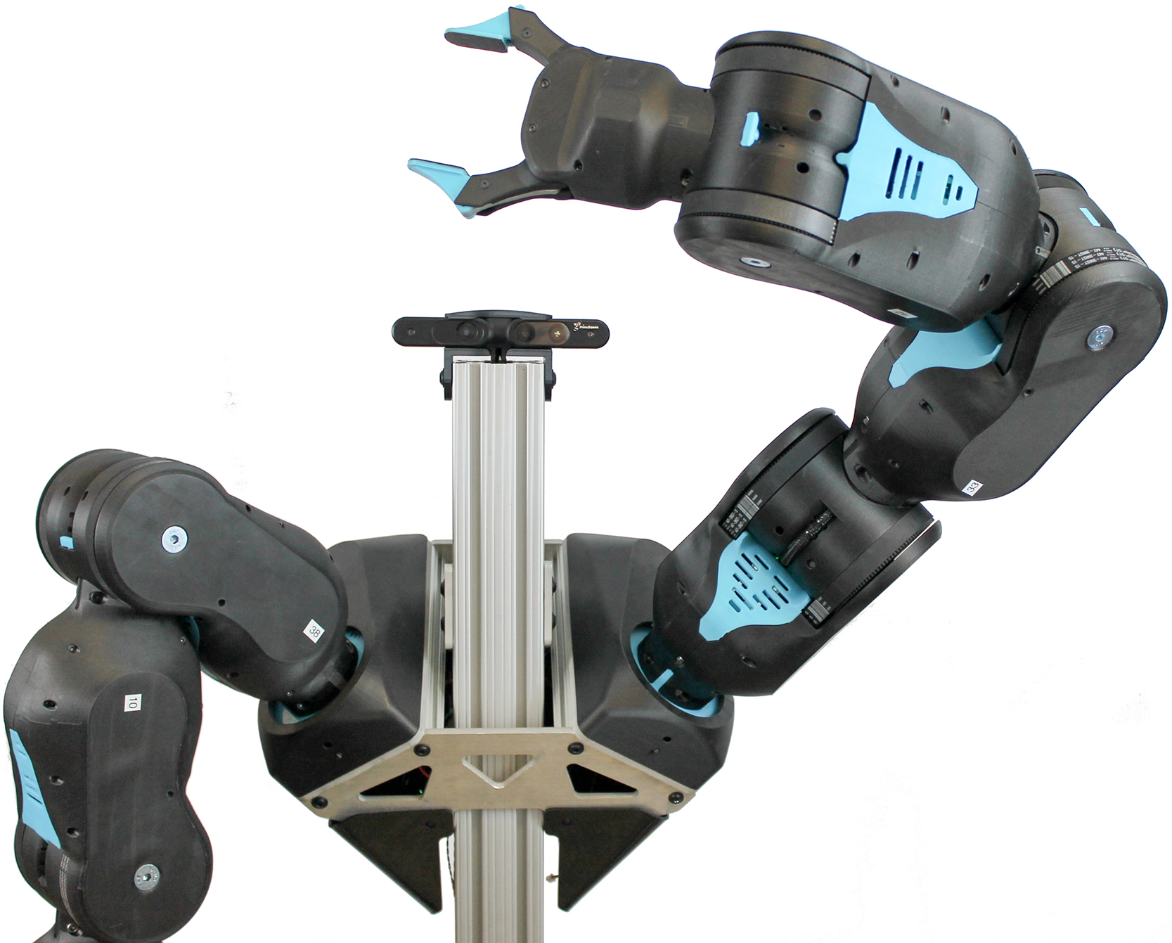
A kinematically-anthropomorphic robot (7 Degree of Freedom comprising 3 in the shoulder, 1 in the elbow, and 3 in the wrist) as shown in Figure 1, can better mimic human motions, allowing better maneuverability in human environments, and enabling more intuitive teleoperation. This can be useful in Learning from Demonstration (LfD), where human operators provide demonstrations of tasks through methods including Virtual Reality (VR) teleoperation [1] [2].
If robot cost is reduced, iterative methods such as Reinforcement Learning (RL) which seek to maximize a given reward through the repeated refinement of a learned policy can be accelerated efficiently by allowing multiple systems to run policy refinement and iterate in parallel [3].
Requirements for high robot repeatability may be less important for both teleoperation and learning based methods that use visual feedback [4] [5]. Additionally, recent work utilizing domain randomization for AI-based policy generation suggests that lower-precision hardware can be used for grasping tasks [6]. Training for both LfD and RL often leads to collisions between the robot and environment [7]. Compliant robots can mitigate damage by controlling interaction forces.
These considerations shift the focus of designing hardware away from the constraints of highly structured manufacturing environments (which depend on robots with high repeatability and high bandwidth), and instead moves toward the broader question:
What hardware paradigms will most enable useful automation in unconstrained real-world human environments at low cost?
Contributions: In this paper we present:
-
•
our design criteria for useful robotic manipulation in unconstrained environments,
-
•
an implementation of a robot arm that satisfies the above set of specifications,
-
•
evaluation of the physical characteristics of our new design,
-
•
work towards DFM (design for manufacturing), and
-
•
production cost analysis.
I-B Defining a Useful Robotic Manipulator
We define a design paradigm that enables usefula, low-costb robotic arms capable of manipulation tasksc in unconstrained environments.
a) We define useful in metrics similar to humans: human-size, 7 Degrees of Freedom , 2kg payload, safe, compliant, and with a repeatability under 10mm.
b) We define low-cost as: pricing below $ to an end user for a manufacturing run of more than arms.
c) A partial set of tasks to consider includes: unloading a dishwasher, stocking a refrigerator, floor decluttering, opening doors, opening microwave ovens, sorting packages, physical stroke rehabilitation, folding laundry, cleaning windows, bed making, and bathroom cleaning. We demonstrate the robot in kitchen cleaning, table decluttering, telepresence, and machine tending.
I-C Defining Useful Bandwidth and Payload
Super-human bandwidth and payload capabilities enable high speed and high precision in constrained industrial automation tasks. However, if the goal is to safely manipulate household objects through human teleoperation while minimizing cost, performance trade-offs have to be made. This motivates seeking new definitions for useful bandwidth and payload metrics for our design.
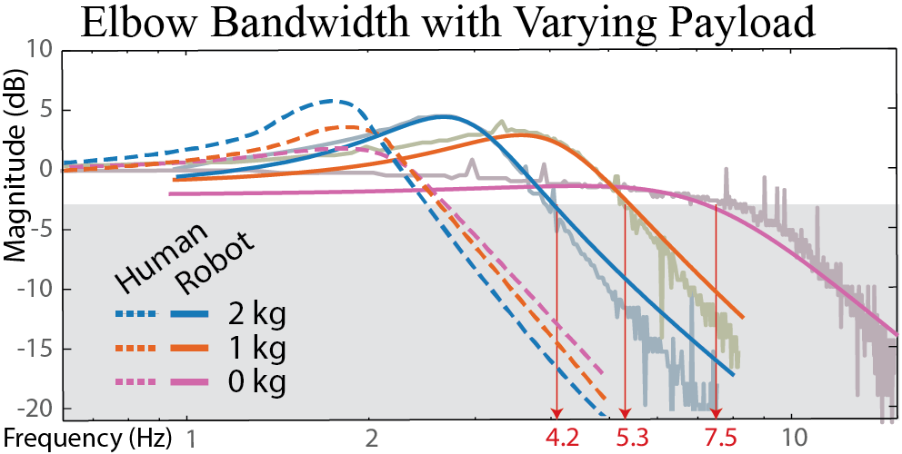
Bandwidth is a measure of an actuator’s ability to deliver force (or control position) at higher frequencies. We believe a manipulator designed for human teleoperation can be perceived as useful as long as the robot’s effective bandwidth is greater than that of the (human) user. As a lower bound for this design: studies on human muscle (biceps brachii) characteristics show that maximum effective position bandwidth is 2.3 Hz as found by Aaron et al [8]. See Figure 2 for a comparison of human bandwidth characteristics and Blue’s properties.
Rated payloads for commercially available robots often cover conservative loading conditions: guaranteeing high-bandwidth trajectory tracking in worst-case positions under continuous operation while holding a maximum ‘rated’ payload. We instead define a useful payload as one that can cover the largest set of outlined tasks, at human speeds. For example, position bandwidth can suffer under high payload, since dexterity at high payload is not universally required for the tasks considered in Section I-B.
Drawing inspiration from nature, we consider how humans subconsciously minimize energy output during manipulation tasks [9]. Human arms have 1:1 arm mass to payload ratio (about kg:kg), but humans cannot maintain full payload constantly (100% duty cycle). For object manipulation, humans have poor steady-state (RMS) force output, yet have high ‘burst power’ capability. Extending this to robot design, overall robot mass and inertia can be reduced if maximum loads are assumed as peaks of short-duration effort rather than requirements for continuous operation. In Section V.E and Figures 10,11 we describe considerations for robots operating within a thermally limited paradigm.
I-D Examining Low-Cost Design Constraints
Our goal is to lower the cost of general purpose robotic manipulators to the point where we can place a robot on the desk of every researcher in our group (the Robot Learning Lab at UC Berkeley). For this to be possible, we believe a system would have to be approximately equal in cost to a high performance research computer ().
II Related Work
II-A Compliance in Robotic Systems
Compliance is the ability for a robot to exhibit low impedance: moving when disturbed by an outside force. A rigid non-compliant (high impedance) robot can be dangerous to operate near humans and destructive to itself or its environment during collisions. However, an entirely compliant robot will not be able to deftly manipulate objects nor respond to high frequency commands (low bandwidth).
Compliance can be passively inherent in systems or actively added to otherwise non-compliant systems. Active compliance can be achieved through sensing of output torques and feedback control and is found in series elastic actuation (SEA) [10] and modern ‘cobots’ [11]. Passive compliance is a characteristic of systems that can be driven by external forces with no use of feedback control.
Passive compliance can be achieved with backdrivable transmissions, wherein external forces applied at the output act on the motor and can be ’sensed’ by measuring motor currents. Backdrivability enables highly robust torque control because the motor also acts as the torque sensor. Co-locating the sensor and actuator significantly eases dynamic stability problems present in force control [12].
High bandwidth actuation combined with inherently backdrivable transmissions allows a robot controller to select impedance (high or low) [13], helping match the unpredictable needs of real-world environments [14]. In the scope of our work, passive compliance is inherent within backdrivable actuation.
II-B Force-Controlled Manipulators at Human Payload
II-B1 Industry Solutions
Kuka’s LBR has excellent closed-loop strain-based force control [15] and sells for upwards of $. The similar Franka Emika arm is available for $. Rethink Robotic’s ‘Baxter’ was $ (for two arms) and has been replaced by a single 7-DOF arm called ‘Sawyer’ available for $. Currently all robots mentioned above except Baxter use harmonic drives which can be made backdrivable with additional sensors but are not inherently compliant.
II-B2 Backdrivable Research Solutions
The Barrett WAM ($) is a highly-backdrivable manipulator accomplishing useful payload by placing all actuators in the base and using low-friction cable transmissions [16]. The Willow Garage PR2 ($ for 2 armed fully integrated mobile manipulator) achieved backdrivability through a gravity compensation mechanism, allowing the undersizing of actuators [17]. The high cost of these platforms was influenced by complex design approaches.
II-C Existing Low-cost Manipulators
Quigley’s Low-Cost Manipulator is an example of robot design built for manipulation research which makes careful design trade-offs balancing elements such as cost, compliance, and payload [18]. Although Bill of Materials (BoM) part cost is estimated at ($), manufacturing costs and complexity were not accounted for.
II-D Actuation Schemes
Successful implementations of series elastic robots have shown that useful tasks can still be completed despite lower mechanical and control bandwidths [22]. However, it is not clear that existing SEA actuator solutions can be made low-cost. Rethink Robotics Baxter is the closest realization of this paradigm at for a two-arm system.
Backdrivable actuation holds promise for robots in unconstrained environments and enables selectable impedance with robust force control. Direct-drive is the most backdrivable, but high motor masses in the arm make high-DoF systems impractical. Recently, Quasi-Direct Drive (QDD) actuators (transmission ratios 1:10) have been used for legged locomotion and have the desirable properties of low friction, high backdrivability, toughness, simplicity, robust force control and selectable impedance [23]. The primary drawback of this actuation method is reduced torque-density [13].
III Design for Low-Cost Compliant Manipulation
A full characterization of our design is shown in Table I.
![[Uncaptioned image]](/html/1904.03815/assets/x1.png)
III-A Quasi-Direct Drive Actuation
QDD was chosen for the Blue system because it can achieve backdrivability in a wide range of transmission options (Gears, Belts, Cables, etc.), and has adequate torque density. Large gap-radius brushless outrunner gimbal motors from iFlight (see Table II) were selected for their exceptional Km density at relatively low cost. Outrunners have higher torque density at the cost of reduced thermal dissipation and increased inertia [24]. Thermal considerations are considered in Section V.
III-B Differential Timing Belt Transmissions
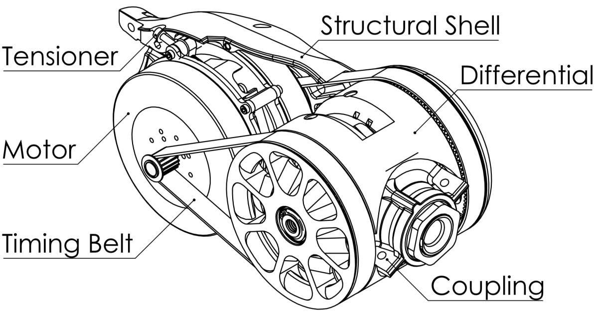
Timing belt transmissions were chosen over cables because of their relative ease of assembly and tensioning, durability, allowance for continuous rotation, efficiency (95%), low backlash, and high backdrivability. 15mm wide GT3 belts with fiberglass tension elements were chosen with 3mm pitch to maximize the feasible single-stage gear ratio, transmitting power from a 16 tooth pinion to a 114 tooth output pulley resulting in a 7.125:1 single-stage reduction. Each link of the robot has a 2-DoF differential output, combining two planar QDD timing belt transmissions into output pitch and roll motions as seen in Figure 3. Benefits of differential drive include partial load sharing when splitting induced gravitational loads.
An advantage of timing belts is their ability to transmit power over distance. Shifting the motor mass towards the shoulder reduces gravity induced torques and flying inertia, helping mitigate poor torque density inherent to QDD actuation. A conservative comparison is produced by locating a summed motor and transmission mass at each DoF, then calculating flying inertia and gravity induced torques about the shoulder. Shifting the motors back using timing belts results in an approximate 30% reduction in both gravity induced torque about the shoulder, and 30% reduction in flying inertia.
Geared differentials were chosen for their simplicity, reliability, impact resistance, continuous rotation, and lower part count. Because the differentials operate at low speed, large plastic teeth can be used under preloads with success.
III-C Modular Structural Shells
Blue is a robot designed for potential interaction with humans. The modular, repeated structural shells are designed to house, protect, and support all components of the arm while concentrating design complexity into a few injection-moldable parts that handle structure, safety from pinch points, and mechanical coupling between stages. The base of each shell is a two-bolt clamp that resists torque in all directions. The coupling between shells is limited in diameter to avoid potential finger-pinch points.

Belt tension is applied by pivoting the servos assemblies away from the output pulleys using a lead screw. A single tension point balances loads on both timing belts. A drawback to this approach is that passive heat transfer from motor to environment is throttled to RMS 10 Watts per stage because the motors are isolated from thermal conductors. This limitation is surmounted using a fan in the base.
III-D Base and Gripper
A 1-DoF timing belt base was developed to create a 3-DoF shoulder. While differential load sharing is removed, mounting the servomotor to a large aluminum base greatly increases both thermal mass and heat dissipation.
A low-cost parallel jaw gripper was designed and implemented as shown in Figure 4. Comparable end-effectors used in research are often $5,000 USD and would defeat the purpose of a low-cost paradigm. A servo module (same as in the rest of the arm) drives a backdrivable lead screw that actuates the four-bar-linkage fingers through a rack-and-pinion. Despite an increasing diversity of gripper paradigms, we chose parallel jaws for their predictability, robustness, simplicity (low cost), and ease of simulation [6].
III-E Motor Drivers and Sensors
Blue’s Quasi-Direct Drive actuation utilizes a single driver board per servo with all sensors co-located to minimize wiring complexity, connector failure points, and manufacturing cost. Custom motor drivers were developed for Blue [25]. Each driver board is equipped with the following sensors: 14-bit absolute on-axis magnetic encoding for motor commutation and robot position sensing; 12-bit current sensing for closed-loop current (and thus torque) control of each servomotor; a 3-axis accelerometer for state estimation, collision detection and control as well as start-up robot calibration as envisioned in [26], and temperature sensors for thermal monitoring and shutdown if needed.
IV System Integration
Power is supplied from a two-quadrant 48V 8A MeanWell switching regulator. Peak power can be anticipated at 250 W instantaneous, and 25 W continuous with no payload. A custom reverse current shunt circuit protects the low-cost power supply from reverse current-flow.
IV-A Control and Communication
Blue’s control system is built around a central control computer (currently an Intel NUC, BOXNUC7I3BNK) that runs Ubuntu Linux and makes heavy use of the ros_control [27] framework. The computer determines actuator torque commands and sends them to each servomotor through a shared RS485 bus running at 170Hz with a 1Mbps data rate. Firmware updates, driver configuration, and motor calibration also leverage the same RS485 bus.
PID joint control is computed with feed-forward gravity and Coriolis compensation torques. Each servomotor locally runs real-time current control at 20kHz.
IV-B Inverse Kinematics
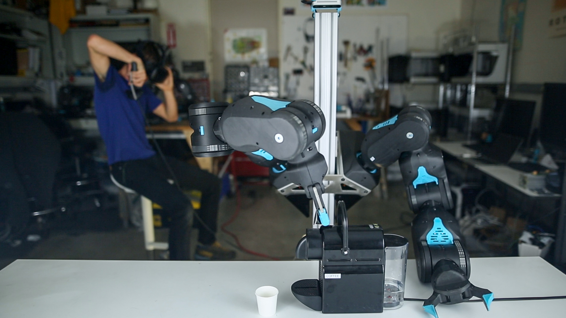
Controlling the 7-DoF end effector in real time through a 6-DoF VR teleoperation interface (as demonstrated in Figure 5) requires a computationally efficient algorithm with joint state continuity. An iterative inverse kinematics solver is used with a secondary joint state objective to constrain the arm’s redundant degree of freedom [28]. Teleoperation was made more intuitive by setting the secondary objective to match a human’s resting position, with elbows naturally oriented. The joint error to this pose is optimized in the null space of the 7-DoF manipulator Jacobian.
Telepresence allows the user to interact with others remotely and in real time. Operation of machinery (Figure 5) is possible using the VR interface and Blue’s compliance allows it to be safely manipulated in human environments.
V Performance Metrics and Experiments
V-A Repeatability Experiments
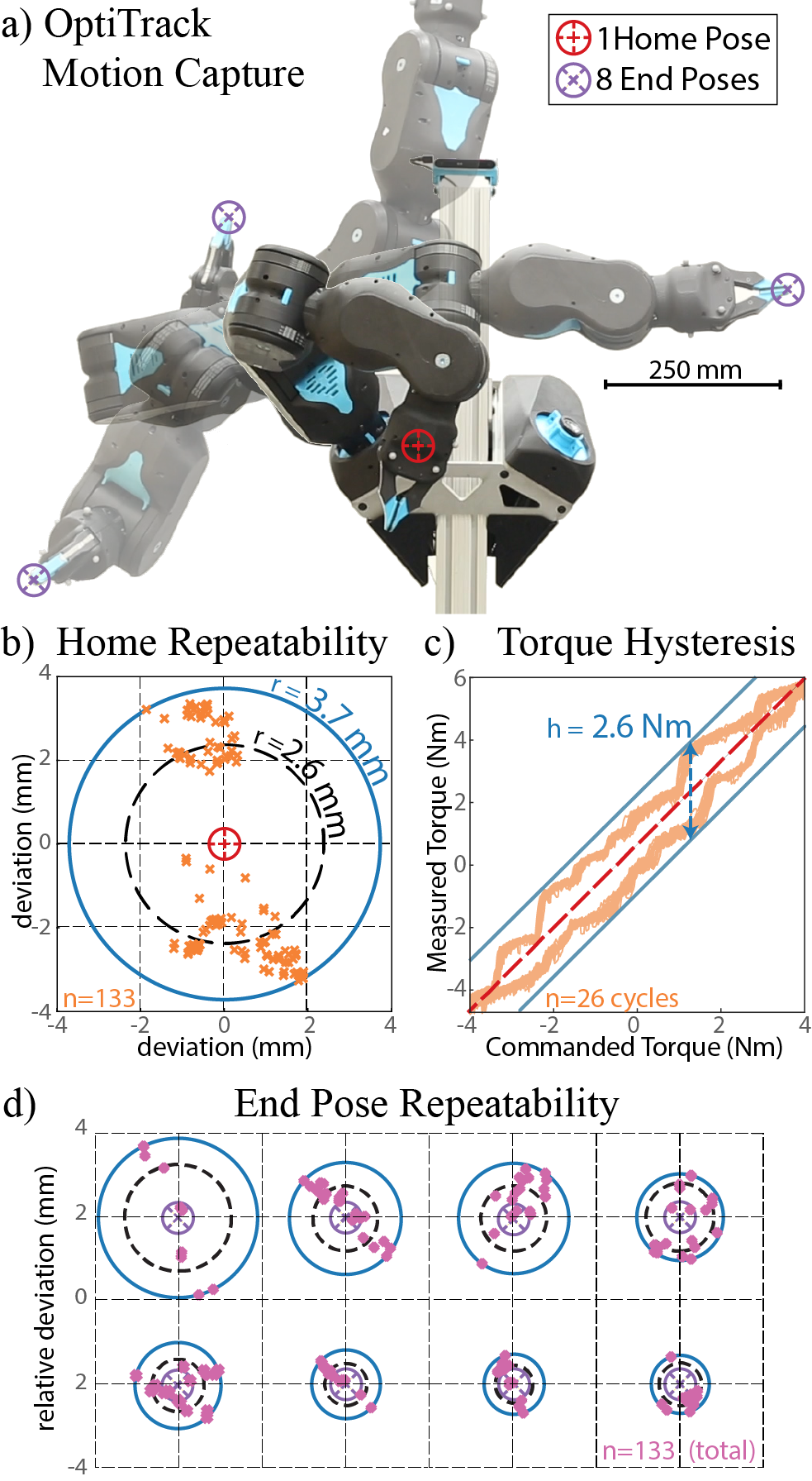
Position-control repeatability was measured (similarly to [18]) by moving from a ‘home’ position to one of eight predefined dwell locations in the robot workspace (chosen in random order) and then back to home as shown in Figure 6.a. Motion was recorded by an OptiTrack motion Capture system at 100Hz. The standard deviation of the home pose was (0.89, 2.2, 1.6) mm for the (x, y, z) axis and (0.53, 0.29, 0.09) degrees for the (roll, pitch, yaw) axis. Figure 6.b shows the distribution of home dwell points during motions sliced across the plane of highest variance. All trials fell within a radius of 3.7 mm and the average deviation from the center of home poses was 2.6 mm. Figure 6.d shows the distribution of end effector poses around each end point. Higher repeatability can be achieved through adding output joint encoders or visual feedback.
V-B Static Torque Hysteresis
Friction (present in all actuators) limits backdrivability and degrades the potential for a motor to act as a torque sensor. This friction results in a torque hysteresis band, the height of which represents a bound on the uncertainty of the mapping between commanded torque and actual output torque. The static torque hysteresis band was measured by locking the actuator output, slowly cycling motor torque, and measuring output torque. The results of this show a worst case bound of 2.6 Nm for a full 2-DoF differential actuating an output roll as shown in Figure 6.c.
Motor cogging torque accounts for 0.47 Nm of a total measured 0.89 Nm backdriving torque per single belt transmission. Torque ripple caused by motor cogging can be seen in 6.c. Although cogging torque is currently lumped with friction, methods exist to reduce this effect through additional calibration and feed-forward control [29].
V-C Position-Control Experiments
A test cell was constructed to secure one 2-DOF modular link and measure output position in real time while incorporating stiffness of the belt transmission (1.3 kNm/rad), and lumping of differential, 3D-printed plastic shells, and 3D-printed joint coupling stiffness (lumped at 1.2 kNm/radian). Masses were held vertically to avoid directional transmission pre-load from gravity and a rotary encoder was used to record arm translation via cable capstan transmission.
V-C1 Step Responses
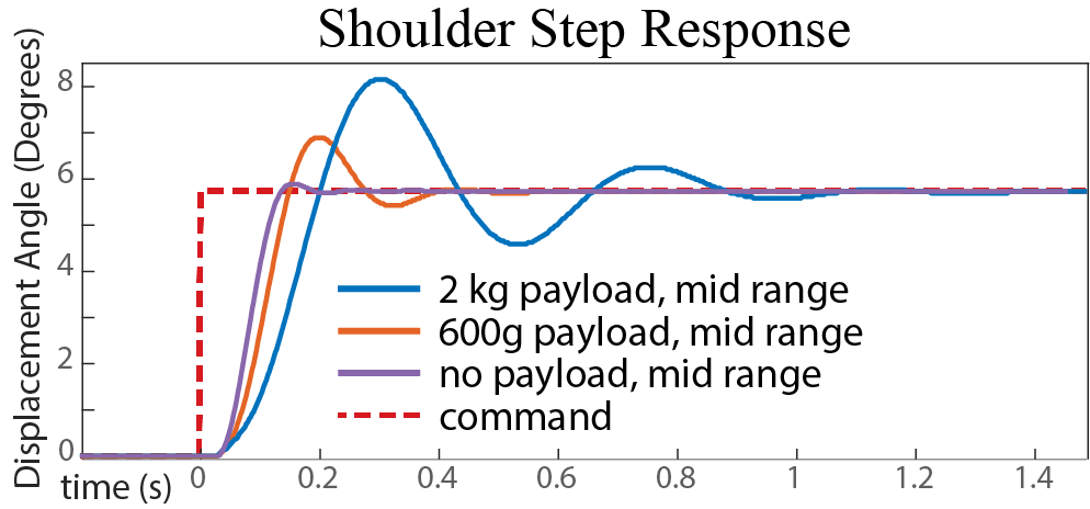
As seen in Figure 7, step responses for the shoulder lift were performed with inertias of (0.13, 0.27, 0.76) kgm2 representing (0, 0.6, 2) kg payloads at mid-range (50-70% robot reach). For a 6 degree step command, overshoot is (0.15, 1.1, 2.3) degrees, resulting in (0.1, 0.8, 2.8) cm of end-effector overshoot at mid-range. Underdamped dynamics can be partially handled through smoother trajectories, provided by either teleoperation or trajectory optimization.
V-C2 Position Bandwidth
Position control bandwidth describes the maximum frequency with which an actuator can effectively track a pose command. Figure 2 compares robot position bandwidth to that of humans’ biceps brachii with varying payloads, while Figure 8 describes position-control bandwidths for the shoulder for various mid-range loads.

V-D Torque Bandwidth Experiments
Torque bandwidth is a measure of how quickly commanded torque can propagate through a transmission, resulting in a change in output torque. High torque bandwidth coupled with backdrivable transmission enables selectable impedance control, wherein the manipulator dynamics can be rapidly changed to best fit the interacting environment. Torque bandwidth was measured to better understand actuator performance in human environments.
Torque bandwidth of a 2-DoF arm link was measured by grounding the actuator output to two 20 kg strain-based load cells whose signal is amplified by dual instrumentation amplifiers and then sampled by a 14bit ADC with digital low-pass filtering, passing the data in real time at 400 Hz to a central computer. A 10Nm chirp signal was commanded from 0.1 to 60 Hz over 300 seconds. As seen in Figure 9, non-linear harmonics in the output frequency response caused output torque to occasionally peak at unity-gain. A conservative estimate of bandwidth torque follows the roll-off of the sampled peaks, resulting in an estimated control bandwidth of 13.8 Hz. The human performance limit in an anthropomorphically analogous setting is 2.3 Hz [8].

V-E Thermal Experiments
Maximizing backdrivability performance for QDD requires running motors near their thermal limits. Heat is generated (almost entirely) within the motors from resistive losses. Achieving peak torque involves driving motors past their continuous thermal limits and motivates thermal testing. Average per-motor power consumption was evaluated then combined with measured thermal dissipation constants to inform peak capabilities of the robot.
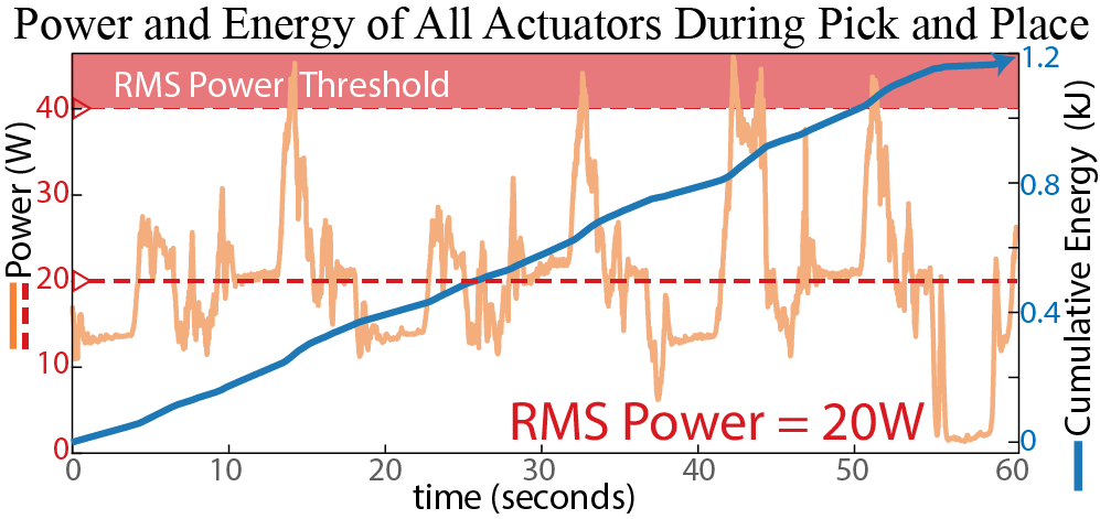
Per-motor power was measured during a 60-second repetitive pick-and-place robot motion. Total RMS motor power is 20 Watts for ‘normal’ movement with no payload (seen in Figure 10).
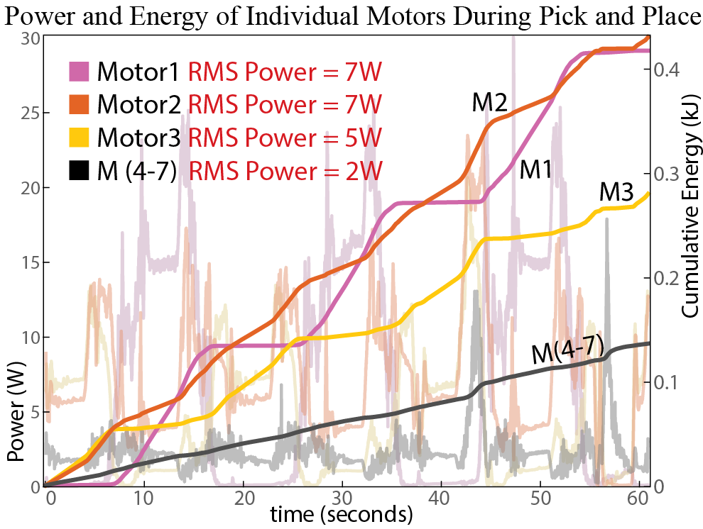
As shown in Figure 11, 90% of power is split between the proximal three arm motors (Base - M1; and Shoulder - M2, M3). Shoulder motors (M2, and M3) dissipate comparable amounts of heat and can be treated conservatively as a lumped thermal model to plan peak (‘burst’) arm capabilities in terms of % duty cycle. Integrated motor power is shown in solid colors, suggesting that simple average power models can be used for normal movement.
The base motor (M1) is bolted directly to a large aluminum base-plate which acts as a heat sink, providing significant thermal overhead. Within the body of the arm, thermal dissipation constants were measured at (0.93 W/°C with a fan, and 0.3 W/°C without a fan). With the fan engaged, shoulder motors can dissipate 40W continuous at 70°C, resulting in a combined 20Nm continuous output torque (0.5kg payload fully outstretched), or 20 Watts of cooling overhead if the established average from Figure 10 is respected.
Assuming a 20 Watt RMS ‘resting’ power, one can temporarily dump heat into the shoulder motors (estimated 1103 Ws/°K heat capacity), producing an excess of 35Nm of torque for 23% of the time (duty cycle): capable of holding a 2kg payload at full extension with a 10 Nm dynamic overhead for upwards of 2 minutes before seeing a °C rise in motor temperature, and having to ‘rest’ for 7 minutes. Shorter bursts are possible with less time spent resting, as long as total average power doesn’t exceed 40 Watts.
V-F Teleoperation Tasks
A set of human tasks were attempted under teleoperation to evaluate the robot’s qualitative performance, one of which is shown in Figure 5. Challenges included gauging object depth through the constrained camera feed of the robot and commanding interaction forces, since a single controller tune was used and the only input is a 6-DOF position target in task-space. Successful tasks included operating an espresso machine, picking up m5 bolts, cleaning a table with paper towels, and decluttering.
VI Manufacturability and Cost Analysis
We designed all plastic components to be injection molded for high volumes, metal pieces to be planar and simple to machine, and hardware to be commodity or sourced from existing high volume products such as bicycles, 3D printers, and drones. In the lab we fabricated seven Blue arms (of the version presented in this paper) for testing. Arms can be deployed minimally as single units with base flat on table.
VI-A Prototype Cost
During a unit fabrication run in-house, Bill of Materials (BoM) cost for each arm was tracked at $ as shown in Table II. Plastics were printed on Markforged Onyx One and Monoprice MP Select Mini 3D printers. About 75% of our prototype costs were motors and driver boards. Machined components were sourced from a machine shops globally. Assembly took about hours per robot arm. Assembly costs were not factored into Table II.
![[Uncaptioned image]](/html/1904.03815/assets/figures/GBM110_PrototypeCost.png)
VI-B Manufacturing and Scaling Cost Analysis
To fully evaluate a low-cost design paradigm for manipulation, we worked with three Contract Manufacturing (CM) companies to identify the costs of Blue arms produced at scale. We received quotes from three CM’s in the California Bay Area from which we based the estimates presented in Table III. Creating tooling for the unique plastic components is estimated at $. Other CM bring-up costs and Non Recoverable Engineering expenses (NRE’s) could total $. As shown in Table III, the end cost to consumers (assuming additional operational margins) can be kept within our $ goal range if producing at volumes above Blue arms.
![[Uncaptioned image]](/html/1904.03815/assets/figures/manufacturingCost.png)
VII Discussion and Future Work
Future mechanical work includes increasing robustness by reducing timing belt skips, implementing a fiber reinforced thermoset polymer shell to avoid long-term structural creep, and adding slip rings to enable continuous rotation, eliminate hard stops, and reduce cable fatigue. Software improvement includes disturbance observers using onboard accelerometers, and fully automatic startup calibration procedures.
Benchmarking compliance across robot platforms would benefit the manipulation community. Future work includes testing and comparing force control capabilities of commercially available robots by measuring Z-width (which represents achievable impedance across frequencies) [30].
Acknowledgments
The Robot Learning Lab (RLL) is part of the University of California, Berkeley. This work is supported in part by the National Science Foundation Graduate Research Fellowship under Grant No. DGE 1752814, NSF Career Grant No. 1351028, the Toyota Research Institute, and by the Bakar Fellows Program. The authors would like to recognize the help of the UC Berkeley Student Machine Shop, Michael McKinley, Morgan Quigley, Roshena Macpherson, Justin Yim, Jeffrey Mahler, and Dominick Kofi Yaate Quaye.
References
- [1] N. Koganti, A. Rahman H. A. G., Y. Iwasawa, K. Nakayama, and Y. Matsuo, “Virtual reality as a user-friendly interface for learning from demonstrations,” in Human Factors in Computing Systems, 2018, ser. CHI EA ’18, 2018.
- [2] T. Zhang, Z. McCarthy, O. Jow, D. Lee, K. Goldberg, and P. Abbeel, “Deep imitation learning for complex manipulation tasks from virtual reality teleoperation,” arXiv preprint arXiv:1710.04615, 2017.
- [3] S. Levine, P. Pastor, A. Krizhevsky, J. Ibarz, and D. Quillen, “Learning hand-eye coordination for robotic grasping with deep learning and large-scale data collection,” The International Journal of Robotics Research, vol. 37, no. 4-5, pp. 421–436, 2018.
- [4] C. Finn, X. Y. Tan, Y. Duan, T. Darrell, S. Levine, and P. Abbeel, “Deep spatial autoencoders for visuomotor learning,” in International Conference Robotics and Automation. IEEE, 2016, pp. 512–519.
- [5] Y. Duan, X. Chen, R. Houthooft, J. Schulman, and P. Abbeel, “Benchmarking deep reinforcement learning for continuous control,” in International Conference on Machine Learning, 2016, pp. 1329–1338.
- [6] J. Mahler, J. Liang, S. Niyaz, M. Laskey, R. Doan, X. Liu, J. A. Ojea, and K. Goldberg, “Dex-net 2.0: Deep learning to plan robust grasps with synthetic point clouds and analytic grasp metrics,” arXiv preprint arXiv:1703.09312, 2017.
- [7] M. P. Deisenroth, C. E. Rasmussen, and D. Fox, “Learning to control a low-cost manipulator using data-efficient reinforcement learning,” in Robotic Systems and Science, vol. 7. MIT Press, 2011, pp. 57–64.
- [8] S. Aaron and R. Stein, “Comparison of an emg-controlled prosthesis and the normal human biceps brachii muscle.” American journal of physical medicine, vol. 55, no. 1, pp. 1–14, 1976.
- [9] Z. Mi, J. J. Yang, and K. Abdel-Malek, “Optimization-based posture prediction for human upper body,” Robotica, vol. 27, no. 4, pp. 607–620, 2009.
- [10] G. A. Pratt, M. M. Williamson, P. Dillworth, J. Pratt, and A. Wright, “Stiffness isn’t everything,” in experimental robotics IV. Springer, 1997, pp. 253–262.
- [11] A. Albu-Schäffer, S. Haddadin, C. Ott, A. Stemmer, T. Wimböck, and G. Hirzinger, “The dlr lightweight robot: design and control concepts for robots in human environments,” Industrial Robot: an international journal, vol. 34, no. 5, pp. 376–385, 2007.
- [12] S. D. Eppinger and W. P. Seering, “Three dynamic problems in robot force control,” IEEE Transactions on Robotics and Automation, vol. 8, no. 6, pp. 751–758, 1992.
- [13] S. Seok, A. Wang, D. Otten, and S. Kim, “Actuator design for high force proprioceptive control in fast legged locomotion,” in Intelligent Robots and Systems (IROS), 2012 IEEE/RSJ International Conference on. IEEE, 2012, pp. 1970–1975.
- [14] M. T. Mason, “Compliance and force control for computer controlled manipulators,” IEEE Transactions on Systems, Man, and Cybernetics, vol. 11, no. 6, pp. 418–432, 1981.
- [15] R. Bischoff, J. Kurth, G. Schreiber, R. Koeppe, A. Albu-Schäffer, A. Beyer, O. Eiberger, S. Haddadin, A. Stemmer, G. Grunwald, et al., “The kuka-dlr lightweight robot arm-a new reference platform for robotics research and manufacturing,” in International symposium on Robotics. VDE, 2010, pp. 1–8.
- [16] W. T. Townsend and J. K. Salisbury, “Mechanical design for whole-arm manipulation,” in Robots and Biological Systems: Towards a New Bionics? Springer, 1993, pp. 153–164.
- [17] K. A. Wyrobek, E. H. Berger, H. M. Van der Loos, and J. K. Salisbury, “Towards a personal robotics development platform: Rationale and design of an intrinsically safe personal robot,” in Robotics and Automation, 2008. ICRA 2008. IEEE International Conference on. IEEE, 2008, pp. 2165–2170.
- [18] M. Quigley, A. Asbeck, and A. Ng, “A low-cost compliant 7-dof robotic manipulator,” in Robotics and Automation (ICRA), 2011 IEEE International Conference on. IEEE, 2011, pp. 6051–6058.
- [19] T. Yamamoto, T. Nishino, H. Kajima, M. Ohta, and K. Ikeda, “Human support robot (hsr),” in ACM SIGGRAPH 2018 Emerging Technologies. ACM, 2018, p. 11.
- [20] E. Eaton, C. Mucchiani, M. Mohan, D. L. Isele, J. M. Luna, and C. Clingerman, “C.: Design of a low-cost platform for autonomous mobile service robots,” in IJCAI Workshop on Autonomous Mobile Service Robots, 2016.
- [21] “7bot: a $350 robotic arm that can see, think and learn!” Nov 2015. [Online]. Available: https://kck.st/1JcKvHG
- [22] A. Edsinger-Gonzales and J. Weber, “Domo: a force sensing humanoid robot for manipulation research.” in Humanoids, vol. 1, 2004.
- [23] S. Kalouche, “Design for 3d agility and virtual compliance using proprioceptive force control in dynamic legged robots,” no. August, 2016.
- [24] J. W. Sensinger, S. D. Clark, and J. F. Schorsch, “Exterior vs. interior rotors in robotic brushless motors,” in International Conference on Robotics and Automation. IEEE, 2011, pp. 2764–2770.
- [25] A. Zhao, “Design of a brushless servomotor for a low-cost compliant robotic manipulator,” Master’s thesis, EECS Department, University of California, Berkeley, May 2018.
- [26] M. Quigley, R. Brewer, S. P. Soundararaj, V. Pradeep, Q. Le, and A. Y. Ng, “Low-cost accelerometers for robotic manipulator perception,” in Intelligent Robots and Systems (IROS), 2010 IEEE/RSJ International Conference on. IEEE, 2010, pp. 6168–6174.
- [27] S. Chitta, E. Marder-Eppstein, W. Meeussen, V. Pradeep, A. R. Tsouroukdissian, J. Bohren, D. Coleman, B. Magyar, G. Raiola, M. Lüdtke, et al., “ros_control: A generic and simple control framework for ros,” The Journal of Open Source Software, vol. 2, no. 20, pp. 456–456, 2017.
- [28] B. Siciliano and O. Khatib, in Springer Handbook of Robotics. Berlin, Heidelberg: Springer-Verlag, 2007, pp. 247–251.
- [29] M. Piccoli and M. Yim, “Anticogging: Torque ripple suppression, modeling, and parameter selection,” The International Journal of Robotics Research, vol. 35, no. 1-3, pp. 148–160, 2016.
- [30] D. W. Weir, J. E. Colgate, and M. A. Peshkin, “Measuring and increasing z-width with active electrical damping,” in Haptic interfaces for virtual environment and teleoperator systems, 2008. Haptics 2008. Symposium on. IEEE, 2008, pp. 169–175.