The link to the formal publication is via
https://doi.org/10.1007/s11390-007-9007-9
Higher-Level Hardware Synthesis of The KASUMI
Algorithm
Issam W. Damaj
Electrical and Computer Engineering Department, Hariri
Canadian Academy of Sciences and Technology, Meshref P.O.Box: 10 Damour- Chouf 2010 Lebanon
E-mail: damajiw@hariricanadian.edu.lb
Abstract Programmable Logic Devices (PLDs) continue to grow in size and currently contain several millions of gates. At the same time, research effort is going into higher-level hardware synthesis methodologies for reconfigurable computing that can exploit PLD technology. In this paper, we explore the effectiveness and extend one such formal methodology in the design of massively parallel algorithms. We take a step-wise refinement approach to the development of correct reconfigurable hardware circuits from formal specifications. A functional programming notation is used for specifying algorithms and for reasoning about them. The specifications are realised through the use of a combination of function decomposition strategies, data refinement techniques, and off-the-shelf refinements based upon higher-order functions. The off-the-shelf refinements are inspired by the operators of Communicating Sequential Processes (CSP) and map easily to programs in Handel-C (a hardware description language). The Handel-C descriptions are directly compiled into reconfigurable hardware. The practical realisation of this methodology is evidenced by a case studying the third generation mobile communication security algorithms. The investigated algorithm is the KASUMI block cipher. In this paper, we obtain several hardware implementations with different performance characteristics by applying different refinements to the algorithm. The developed designs are compiled and tested under Celoxica’s RC-1000 reconfigurable computer with its 2 million gates Virtex-E FPGA. Performance analysis and evaluation of these implementations are included.
Keywords Data encryption, Formal Models, Gate Array, Methodologies, Parallel algorithms
1 Introduction
The rapid progress and advancement in electronic chips technology provides a variety of new implementation options for system engineers. The choice varies between the flexible programs running on a general purpose processor (GPP) and the fixed hardware implementation using an application specific integrated circuit (ASIC). Many other implementation options present, for instance, a system with a RISC processor and a DSP core. Other options include graphics processors and microcontrollers. Specialist processors certainly improve performance over general-purpose ones, but this comes as a quid pro quo for flexibility. Combining the flexibility of GPPs and the high performance of ASICs leads to the introduction of reconfigurable computing (RC) as a new implementation option with a balance between versatility and speed.
Field Programmable Gate Arrays (FPGAs), nowadays are important components of RC-systems, have shown a dramatic increase in their density over the last few years. For example, companies like Xilinx [1] and Altera [2] have enabled the production of FPGAs with several millions of gates, such as in Virtex-II Pro and Stratix-II FPGAs. The versatility of FPGAs, opened up completely new avenues in high-performance computing.
The traditional implementation of a function on an FPGA is done using logic synthesis based on VHDL, Verilog or a similar HDL (hardware description langauge). These discrete event simulation languages are rather different from languages, such as C, C++ or JAVA. An interesting step towards more success in hardware compilation is to grant a higher-level of abstraction from the point of view of programmer. Designer productivity can be improved and time-to-market can be reduces by making hardware design more like programming in a high-level langauge. Recently, vendors have initiated the use of high-level languages dependent tools like Handel-C [3], Forge [4], Nimble [5], and SystemC [6].
With the availability of powerful high-level tools accompanying the emergence of multi-million FPGA chips, more emphasis should be placed on affording an even higher level of abstraction in programming reconfigurable hardware. Building on these research motivations, in the work in hand, we extend and examine a methodology whose main objective is to allow for a higher-level correct synthesis of massively parallel algorithms and to map (compile) them onto reconfigurable hardware. Our main concern is with behavioural refinement, in particular the derivation of parallel algorithms. The presented methodology systematically transforms functional specifications of algorithms into parallel hardware implementations. It builds on the work of Abdallah and Hawkins [7, 8] extending their treatment of data and process refinement.
This paper is divided so that some of the following sections introduce the adopted development methodology. Section 3 presents the theoretical background. In Section 4, we put some emphasis on the approach to develop different implementations of the KASUMI cryptographic algorithm. The following section details the development steps. Section 7 demonstrates selected implementations. In Section 8, we analyze and evaluate the performance of the suggested implementations. Finally, Section 10 concludes the paper.
2 The Development Method
The suggested development model adopts the transformational programming approach for deriving massively parallel algorithms from functional specifications (See Figure 1). The functional notation is used for specifying algorithms and for reasoning about them. This is usually done by carefully combining a small number of higher-order functions that serve as the basic building blocks for writing high-level programs. The systematic methods for massive parallelisation of algorithms work by carefully composing an ”off-the-shelf” massively parallel implementation of each of the building blocks involved in the algorithm. The underlying parallelisation techniques are based on both pipelining and data parallelism.

Higher-order functions, such as map, filter, and fold, provide a high degree of abstraction in functional programs [9]. Not only they do allow clear and succinct specifications for a large class of algorithms, but they also are ideal starting points for generating efficient implementations by a process of mathematical calculation using Bird-Meertens Formalism (BMF). The essence of this approach is to design a generic solution once, and to use instances of the design many times for various applications. Accordingly, this approach allows portability by implementing the design on different parallel architectures.
In order to develop generic solutions for general parallel architectures it is necessary to formulate the design within a concurrency framework such as Hoare’sCSP [10]. Often parallel functional programs show peculiar behaviours which are only understandable in the terms of concurrency rather than relying on hidden implementation details. The formalisation in CSP (of the parallel behaviour) leads to better understanding and allows for analysis of performance issues. The establishment of refinement concepts between functional and concurrent behaviours may allow systematic generation of parallel implementations for various architectures.
The previous stages of development require a back-end stage for realising the developed designs. We note at this point that the Handel-C language relies on the parallel constructs in CSP to model concurrent hardware resources. Mostly, algorithms described with CSP could be implemented with Handel-C. Accordingly, this langauge is suggested as the final reconfigurable hardware realisation stage in the proposed methodology. It is noted that, for the desired hardware realisation, Handel-C enables the integration with VHDL and EDIF (Electronic Design Interchange Format) and thus various synthesis and place-and-route tools.
3 Background
Abdallah and Hawkins defined in [8] some constructs used in the development model. Their investigation looked in some depth at data refinement; which is the means of expressing structures in the specification as communication behaviour in the implementation.
3.1 Data Refinement
In the following we present some datatypes used for refinement, these are stream, vector, and combined forms.
The stream is a purely sequential method of communicating a group of values. It comprises a sequence of messages on a channel, with each message representing a value. Values are communicated one after the other. Assuming the stream is finite, after the last value has been communicated, the end of transmission (EOT) on a different channel will be signaled. Given some type A, a stream containing values of type A is denoted as .
Each item to be communicated by the vector will be dealt with independently in parallel. A vector refinement of a simple list of items will communicate the entire structure in a single. Given some type A, a vector of length n, containing values of type A, is denoted as .
Whenever dealing with multi-dimensional data structures, for example, lists of lists, implementation options arise from differing compositions of our primitive data refinements - streams and vectors. Examples of the combined forms are the Stream of Streams, Streams of Vectors, Vectors of streams, and Vectors of Vectors. These forms are denoted by: , , , and .
3.2 Process Refinement
The refinement of the formally specified functions to processes is the key step towards understanding possible parallel behaviour of an implementation. In this section, the interest is in presenting refinements of a subset of functions - some of which are higher-order. A bigger refined set of these functions is discussed in [7].
Generally, These highly reusable building blocks can be refined to CSP in different ways. This depends on the setting in which these functions are used (i.e. with streams, vectors etc.), and leads to implementations with different degrees of parallelism. Note that we don’t use CSP in a totally formal way, but we use it in a way that facilitates the Handel-C coding stage later. Recall for the following subsections that values are communicated through as an elements channel, while a single bit is communicated through another eotChannel channel to signal the end of transmission (EOT).
3.2.1 Basic Definitions
The produce/store process (PRD/STORE) is fundamental to process refinement. It is used to produce/store values on/from the channels of a certain communication construct (Item, Stream, Vector, and so on). These values are to be received and manipulated by another processes.
The feed operator in CSP models function application. The feed operator is written .
Consider a potential refinement for , a process . The operator denotes a process refinement, where the left hand side is a function, and the right hand side is a process. To state that is refined to , or in other words, the process is a valid refinement of the function , the following may be used:
These rules were proven once [7], and in this paper we use them systematically to refine the functional specification into a network of communicating processes.
3.2.2 Process Refinement of Higher-order Functions
Now the attention is turned to the refinement of higher-order functions presented in [8], showing the refinement of the high-order function map as an instance. Employing this function in stream and vector settings is presented.
Streams
A process implementing the functionality of in stream terms should input a stream of values, and output a stream of values with the function applied.
In general, the handling of the EOT channels will be the same. However, the handling of the value will vary depending on the type of the elements of the input and output stream.
Vectors
In functional terms, the functionality of in a list setting is modelled by in the vector setting. Consider as a valid refinement of the function . The implementation of can then proceed by composing instances of in parallel, and directing an item from the input vector to each instance for processing. In CSP we have:
3.3 Handel-C as a Stage in the Development Model
Based on datatype refinement and the skeleton afforded by process refinement, the desired reconfigurable circuits are built. Circuit realisation is done using Handel-C, as it is based on the theories of CSP [10] and Occam [11].
From a practical standpoint, each refined datatype is defined as a structure in Handel-C, while each process is implemented as a macro procedure. We divide the constructs corresponding to the CSP stage into 2 main categories for organisation purposes. The first category represents the definitions of the refined datatypes. The second category implements the refined processes.
The refined processes are divided into different groups; the utility, basic, higher-order processes. A separate group contains the macros that handle the FPGA card setup and general functionality.
The datatypes definitions are implemented using structures. This method supports recursive as well as simple types. The definition for an Item of a type Msgtype is a structure that contains a communicating channel of that type.
 #define Item(Name, Msgtype)
    struct {
        chan Msgtype    channel;
        Msgtype         message;
        } Name
For generality in implementing processes the type of the communicating structure is to be determined at compile time. This is done using the typeof type operator, which allows the type of an object to be determined at compile time. For this reason, in each structure we declare a message variable of type Msgtype.
A stream of items, called StreamOfItems, is a structure with three declarations a communicating channel, an EOT channel, and a message variable [8]:
 #define StreamOfItems(Name, Msgtype)
    struct {
        Msgtype         message;
        chan Msgtype    channel;
        chan Bool       eotChannel;
        } Name
A vector of items, called VectorOfItems, is a structure with a variable message and another array of sub-structure elements [8].
 #define VectorOfItems(Name, n, Msgtype)
    struct {
        struct {
            chan Msgtype    channel;
            } elements[n];
        Msgtype     message;
        } Name
Other definitions are possible, but it affects the way a channel is called using the structure member operator (.).
The utility processes used in the implementation are related to the employed datatypes. The Handel-C implementation of these processes relies on their corresponding CSP implementation. In the following, we present an instance of these utility macros.
 macro proc ProduceItem(Item, x){
    Item.channel ! x;}

 macro proc StoreItem(Item, x){
    Item.channel ? x;}
This group of macros represents the fine-grained processes. A sample basic macro procedure Addition is included as an example.
 macro proc
  Addition(xItem, yItem, output){
   typeof (xItem.message) x,y;
   xItem.channel ? x;
   yItem.channel ? y;
   output.channel ! (x + y);}
3.3.1 Higher-Order Processes Macros
An example for an implementation in Handel-C of the CSP refinement of a higher-order function (map) in its vector setting is done as follows:
 macro proc
  VMAP (n, vectorin, vectorout, F) {
   typeof (n) c;
   par (c = 0 ; c < n ; c++){
      F(vectorin.elements[c],
        vectorout.elements[c]);}}
In a similar procedure to what have been introduced before, the implementations of the stream and vector settings SZipWith and VZipWith are straightforward.
Different tools are used to measure the performance metrics used for the analysis. These tools include the design suite (DK) from Celoxica, where we get the number of NAND gates for the design as compiled to the Electronic Design Interchange Format (EDIF). The DK also affords the number of cycles taken by a design using its simulator. Accordingly, the speed of a design could be calculated depending on the expected maximum frequency of the design. The maximum frequency could be determined by the timing analyzer. To get the practical execution time as observed from the computer hosting the RC-1000, the C++ high-precision performance counter is used. The information about the hardware area occupied by a design, i.e. number of Slices used after placing and routing the compiled code, is determined by the ISE place and route tool from Xilinx.
4 The Third Generation of Mobile System Security Algorithms
The KASUMI is a modern and strong encryption algorithm designed for the use in the Third Generation Partnership Project (3GPP) security functions for mobile systems [12]. KASUMI ciphers a 64-bit input data block by repeating a round procedure 8 times. The round composes a 32-bit non-linear mixing block (FO) and a 32-bit linear mixing block (FL). The FO-block is an iterated ”ladder-design” consisting of 3 rounds of a 16-bit non-linear mixing block FI. In turn, FI randomising function is defined as a 4-round structure using non-linear look-up tables S7 and S9. All functions involved will mix the data input with key. The used S7 and S9 have been designed in a way that avoids linear structures in FI - this fact has been confirmed by statistical testing. Each functional component of KASUMI has been carefully studied to reveal any weakness that could be used as a basis for an attack on the entire algorithm. The fact that the key schedule of KASUMI is very simple did not constitute any real weakness. There seems to be no gain in practice by making it more complicated.
Hardware implementation of this cryptographic algorithm is currently an active area of research. The KASUMI was addressed by HoWon et al [13], and Alcantara et al [14]. Intel [15] proposed architecture processors for 3G control including the KASUMI. Moreover, SCIWORX [16] produced a system board for the KASUMI cipher.
5 Formal Functional Specification
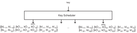
We will consider the following specifications for the key scheduler, and the main algorithm (KASUMI). The key scheduler takes the private key as an input, and outputs a desired set of subkeys. This set of subkeys is of 4 packs (See Figure 2). The KASUMI takes two inputs, the generated subkeys and the input data, and it gives their corresponding output.
Generally, the functional specification style applied throughout this research uses higher-order functions as the main keys for later parallelism. As a start, we define some types to be used in the following formal specification:
 type Private = [Bool]
 type SubKey = [Bool]
 type DataBlock = [Bool]
The following specifications are also tested using the Hugs98 Haskell compiler.
5.1 Key Scheduling
As shown in Figure 2, the 64 16-bit subkeys are organised into 4 packs of 8 sets of subkeys and , where i is an index corresponding to the round number where a subkey is to be used. These subkeys are generated from the 128-bit encryption private key.
Key scheduling is specified as the function keySchedule that inputs a private key and
outputs 4 packs of subkeys. We divide each pack into 6 groups for later ease of distribution to
the encrypting rounds. Each group is a list of subkeys selected from the predefined lists
and . For instance, the
first pack would contain:
The specification of keySchedule is formalised as follows:
 keySchedule :: Private -> [[[Subkey]]]
 keySchedule key = merge(g)
   where
   [kLi1, kOi1, kOi2, kOi3]  =
   mapWith
    (map map [(shift 1), (shift 5),
              (shift 8), (shift 13)])
    (mapWith [id, (shift 1),
              (shift 5),(shift 6)]
    (copy (segs 16 key) 4))

   [kLi2, kIi1, kIi2, kIi3]  =
   mapWith [(shift 2), (shift 4),
            (shift 3), (shift 7)] (
           copy ks’ 4)

   ks’ = zipWith  fullexor (segs 16 key)
   (map itob [291, 17767, 35243, 52719,
              65244, 47768, 30292, 12816])

   g = ((map group).transpose)
       [kLi1, kLi2, kOi1, kOi2, kOi3,
       kIi1, kIi2, kIi3]

   merge(gr) =
    [(gr!!i)++(gr!!(i+1)) |
                        i <- [0,2,4,6]]
The function keySchedule generates the subkeys by firstly determining the predefined ks and ks’. ks is specified using the function segs as (segs 16 key). Recall that segs selects n sublists from a list xs.
After specifying ks, we formalise the computation for ks’ using the higher-order function zipWith zipping two lists with the function exor. These lists corresponds to ks and C. After ks and ks’ are ready, KASUMI subkeys are determined employing the higher-order functions mapWith and map. Also, using the functions shift and copy.
Finally, the functions group and transpose arrange the subkeys in the form mentioned earlier. The arranged groups are then merged into final 4 packs. To easily understand these steps we include the chart shown in Figure LABEL:keySchChart.
5.2 The KASUMI Block Cipher
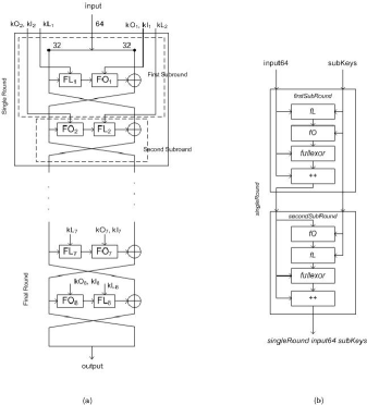
The KASUMI block cipher has two inputs, a 64-bit data block in addition to the private key. The corresponding ciphered output is also a 64-bit data block. In this specification, we suggest the division of the KASUMI structure into 4 similar rounds. Where each single round is of two subrounds, called first and second subrounds. The 4 generated packs of subkeys (using the function keySchedule) are distributed to the KASUMI 4 rounds respectively. The total 8 subrounds of the KASUMI constitute a Feistel network. This is visualised in Figure 3.
KASUMI is formally specified as the function kasumi which inputs two lists of bool input and key. This function outputs a list of bool corresponding to the ciphered data. The specification is done by folding a function singleRound with the input over the generated subkeys packs. With respect to the network shape, the foldable single round is specified as the function singleRound.
 kasumi ::
   DataBlock -> Private -> DataBlock
 kasumi input key =
   foldl singleRound input
                     (keyScheduling key)
A single round is of two blocks, the odd block formalised as the function firstSubRound and the even round formalised as the function secondSubRound. The function singleRound is specified as the functional composition of the functions firstSubRound and secondSubRound. The inputs to the function singleRound are an input block of data and a single pack of subkeys.
 singleRound ::
 DataBlock -> [[Subkeys]] -> DataBlock

 singleRound input64 subKeys =
 secondSubRound (firstSubRound input64
                               subKeys)
The function firstSubRound could be described as follows. It firstly takes the 64-bit data input block and divides it into two left and right 32-bit words as shown in Figure 3. It also inputs a pack of subkeys and distributes them to their specific destinations. The data input left half is passed to a function fL, which corresponds to the FL block. The function fL forwards its output to a function fO (the functional specification of the FO block). The output from the function fO is XORed with the right half of the input data giving the final left half l1. The firstSubRound outputs a 64-bit word, which is the concatenation of the final left half with the initial left half. Also, it outputs the subkeys needed for the second subround.
 firstSubRound ::
 DataBlock -> [[SubKey]] ->
            (DataBlock,[[SubKey]])

 firstSubRound
  input64 [kLo, kOo, kIo, kLe, kOe, kIe] =
   (l1++r1, [kLe, kOe, kIe])

  where
  [r1, r0]=
    [take 32 input64, drop 32 input64]

  [l1, t1, t2]=
    [(fullexor r0 t2),
     (fL r1 kLo),
     (fO t1 kOo kIo)]
The function secondSubRound divides the input 64-bit data block into two left and right halves. The left half with the suitable subkeys are passed to the function fO. The output from the function fO is forwarded to the function fL. The output from the function fL is XORed with the input right half to give the final left half l2. The secondSubRound outputs a 64-bit word, which is the concatenation of the final left half with the final right half r2.
 secondSubRound ::
  (DataBlock, [[SubKey]]) -> DataBlock

 secondSubRound
  (input64, [kL, kO, kI])  = l2 ++ r2

  where
  [r1, r2]= [drop 32 input64,
             take 32 input64]

  [l2, t1, t2]= [(fullexor r1 t2),
                 (fO r2 kO kI),
                 (fL t1 kL)]
The remaining fL, fI, fO, s7, and s9 building blocks are specified in a similar style.
6 Algorithms Refinements
We move now to the second stage of development following the same proposed method. The refinement of the key scheduling, and the KASUMI specifications are presented in the following subsections.
6.1 Key Scheduling
Getting closer to hardware implementation, the general datatypes used in specifying the
function keySchedule are refined as follows:
The key is a 128-bit Integer item, and the output packs of groups of lists can be refined to a
vector of 4 vectors, each of 6 vectors of 16-bit Integer items. The refined processes
KEYSCHEDULE corresponds to the function keySchedule.
From the specification, the process KEYSCHEDULE inputs the key and then it divides it into segments using the process SEGS the refinement of segs. These segments are broadcasted to be later used for 5 times. At this point, two parallel events could occur corresponding to the right and left branches depicted in Figure 4. The right branch of processes refines the following part of the specification:
 ks’ = zipWith  fullexor (segs 16 key)
      (map itob [291, 17767, 35243,
                 52719, 65244, 47768,
                 30292, 12816])

 [kLi2, kIi1, kIi2, kIi3]  =
   mapWith [(shift 2), (shift 4),
            (shift 3), (shift 7)]

            (copy ks’ 4)
To compute for ks’ the vector setting refinement of zipWith (VZIPWITH) is used. Then the vector refinement of mapWith, VMAPWITH, is used to compute for the first set of subkeys.
The parallel left branch of processes computes for the second set of subkeys by piping two instances of the refined process VMAPWITH. This refines the following recalled specification:
 [kLi1, kOi1, kOi2, kOi3]  =
 mapWith (map map
  [(shift 1),(shift 5),
  (shift 8), (shift 13)])

  (mapWith
  [id, (shift 1), (shift 5),(shift 6)]
   (copy (segs 16 key) 4))
The remaining processes are used to refine the functions responsible for ordering the subkeys in
the suggested form - packs of groups of lists. The complete network of processes (see
Figure 4) is described as follows:
where
The process TRANSPOSE is the standard matrix transpose.

6.2 The KASUMI Block Cipher
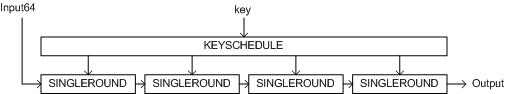
The KASUMI block is the main ciphering part used for the confidentiality and integrity algorithms standardised for 3GPP. Based on the functional specification stage of development, we suggest two refined designs for implementing the KASUMI block. The first is a 4 rounds pipelined design, while the second proposes a single round stream-based design.
6.2.1 First Design
In this design, we construct a fully pipelined network implementing the KASUMI block. Four single rounds are replicated to work in parallel forming a pipeline of processes. Accordingly, this design is expected to have a high degree of parallelism, and therefore to be highly efficient. However, this processes-replicating implementation will require the use of large amounts of processing resources.
The first step in refining the function kasumi observes its inputs as items with a
precision of 64 bits for the data block and 128 bits for the key. This is described as follows:
where
As for this design, the four groups of subkeys are piped from the process KEYSCHEDULE to
the replicated SINGLEROUND processes. The foldl higher-order function in this
case is refined to its vector setting VVFOLDL. Thus, the process KASUMI is
refined as follows:
Note that the upper input to each SINGLEROUND is a list of list of subkeys, refined as a vector of vectors. This is depicted in Figure 5.
Moving to the refinement KASUMI sub-blocks, datatypes employed in the function
singleRound could be refined as follows:
where
Recall the functional specification for a singleRound, we have:
 singleRound input64 subKeys =
    secondSubRound
    (firstSubRound input64 subKeys)
This functional composition is refined to piping of two processes
FIRSTSUBROUND and SECONDSUBROUND. The process
SINGLEROUND is depicted in Figure 6 (a) and
described as follows:
where

In refining the function firstSubRound, the datatypes could be refined as follows:
Recalling the functional specification:
 firstSubRound input64
  [kLo, kOo, kIo, kLe, kOe, kIe] =
  (l1++r1, [kLe, kOe, kIe])
  where
  [r1, r0]= [take 32 input64,
             drop 32 input64]

  [l1, t1, t2] = [(fullexor r0 t2),
                  (fL r1 kLo),
                  (fO t1 kOo kIo)]
The process FIRSTSUBROUND after getting its inputs, and
depending on the functional specification, firstly broadcasts the
input left half r1 to be used twice. Then, the subkeys
are produced to the processes FL and FO in the
order needed. The communications between FL and
FO is implicitly synchronised by the ()
operator. The output from FO is passed to the process
EXOR with the produced input right half. At this point,
the process CONCAT is synchronising on the output of the
processes EXOR and the broadcasted r1. Finally,
the remaining subkeys are produced to be forwarded to the process
SECONDSUBROUND. These processes are shown in
Figure 6 (b).
where
Similarly, and for the function secondSubRound the
refinement is done as follows:
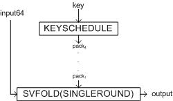
6.2.2 Second Design
In this design, the subkeys packs are passed in a stream setting to a single SINGLEROUND
process. This stream refinement of foldl implemented by SVFOLDL will use the
SINGLEROUND process to compute for the final desired folded result. This design affords
an economical use of computing resources. However, it is a quid pro quo for efficiency. This
CSP network is pictured in Figure 7 and implemented as follows:
6.2.3 Third and Fourth Designs
The aim of introducing the third and fourth designs is to reduce the communication in the fine levels, mainly inside the FL, FI, and FO blocks. These blocks will be implemented with basic operations instead of communicating processes. For example, an addition will be implemented using a (+) operator instead of a process ADDITION. The refinement of the remaining blocks is to be the same. Also, the external communications with the FL, FI, and FO blocks will be the same. The third design uses the new descriptions for the F-blocks to modify the first fully-pipelined design, while the fourth design applies the changes to the second stream-based design.
7 Reconfigurable Hardware Implementations
Based on the refined networks of CSP processes we include samples of the Handel-C code used in the realisation of the hardware circuit.
Getting a sample from KASUMI’s main blocks, we present the macro SingleRound realising the processes SingleRound. The correspondence with the CSP description is very clear by refereing to the implementation presented in the previous stage. In this macro, the macros FirstSubRound and SecondSubRound are piped in parallel to create the macro SingleRound as follows:
 macro proc SingleRound
    (input64, skeysVoV, output64) {

par{
FirstSubRound
    (input64, skeysVoV, midTuple);

SecondSubRound
    (midTuple, output64);}}
The macros implementing the refined network of processes describing the KASUMI, are called from the macro Kasumi. This macro implements the first design.
macro proc Kasumi(input64,
 keysPacks, output64) {

 VFOLDL(input64, keysPacks,
    4, SingleRound, output64);}
8 Performance Analysis and Evaluation
In this paper, we have demonstrated a methodology that can produce intuitive, high-level specifications of algorithms in the functional programming style. The development continues by deriving efficient, parallel implementations described in CSP and realised using Handel-C that can be compiled into hardware on an FPGA. We have provided a concrete study that exploited both data and pipelined parallelism and the combination of both. The implementation was achieved by combining behavioural implementations ’off-the-shelf’ of commonly used components that refine the higher-order-functions which form the building blocks of the starting functional specification.
The development is originated from a specification stage, whose main key feature is its powerful higher-level of abstraction. During the specification, the isolation from parallel hardware implementation technicalities allowed for deep concentration on the specification details. Whereby, for the most part, the style of specification comes out in favor of using higher-order functions. Two other inherent advantages for using the functional paradigm are clarity and conciseness of the specification. This was reflected throughout all the presented studies. At this level of development, the correctness of the specification is insured by construction from the used correct building blocks. The implementation of the formalised specification is tested under Haskell by performing random tests for every level of the specification.
The correctness will be carried forward to the next stage of development by applying the provably correct rules of refinement. The available pool of refinement formal rules enables a high degree of flexibility in creating parallel designs. This includes the capacity to divide a problem into completely independent parts that can be executed simultaneously (pleasantly parallel). Conversely, in a nearly pleasantly parallel manner, the computations might require results to be distributed, collected and combined in some way. Remember at this point, that the refinement steps are systematic and done by combining off-the-shelf reusable instances of basic building blocks.
In the following we will address the results found after compiling, placing and routing, and running the proposed designs. In Table 1 the key scheduling design occupied 8905 Slices and performed at a throughput of 27.7 Mbps. The KASUMI block algorithm in the stream-based second design occupied 13225 Slices and performed at a throughput of 1.68 Mbps (See Table 2). The third and fourth designs outperformed the second design with speeds of 4.92 Mbps and 32 Mbps. The fourth design had a better running frequency (72.71 MHz) than of the third design (49.06 MHz).
These testing results, as compared to the requirements and to other hardware implementations, reveal the high cost of applying the methodology in that manner. Even if some tuning were made, tracking the critical paths in timing analysis to increase the maximum possible frequency of the design does not promote an elevated expectancy of the throughput. The high cost in hardware resources arises from the applied systematic rules blinding possibilities for intuitive ad hoc optimisations. The trials for better speed could continue in a similar way to those undertaken in the KASUMI third and fourth designs. Nevertheless, this lessens the use of communications on the fine-grained processes levels.
![[Uncaptioned image]](/html/1904.03756/assets/KTblEnSKeysSV.jpg)
![[Uncaptioned image]](/html/1904.03756/assets/KTblEnc.jpg)
9 Acknowledgement
I would like to thank Dr. Ali Abdallah, Prof. Mark Josephs, Prof. Wayne Luk, Dr. Sylvia Jennings, and Dr. John Hawkins for their insightful comments on the research which is partly presented in this paper.
10 Conclusion
Recent advances in the area of reconfigurable computing came in the form of FPGAs and their high-level HDLs such as Handel-C. In this paper, we build on these recent technological advances by presenting, demonstrating and examining a systematic approach for synthesizing parallel hardware implementations from functional specifications. We have observed a case study from applied cryptography, namely the KASUMI algorithm for 3GPP. The testing of the realised reconfigurable circuits allowed the ciphering with KASUMI in a throughput of 32 Mbps with an occupied area of 5594 Slices. However, this confirms the conclusion showing the expense of using the higher-level approach adopted. Future work includes extending the theoretical pool of rules for refinement, the investigation of automating the development processes, and the optimisation of the realisation for more economical implementations with higher throughput.
11 References
References
- [1] Xilinx. Information available from. http://www.xilinx.com.
- [2] Altera. Information available from. http://www.Altera.com.
- [3] Celoxica. Information available from. http://www.celoxica.com.
- [4] D. Edwards, S. Harris, and J. Forge. High performance hardware from java. Xilinx Whitepaper http://www.xilinx.com.
- [5] Y. Li, T. Callahan, E. Darnell, R. Harr, U. Kurkure, and J. Stockwood. Hardware-software codesign of embedded reconfigurable architectures. In Proceedings of the 37th Design Automation Conference, page 30, Los Angeles - USA, June 2000.
- [6] SystemC Network. Information available arom. http://www.systemc.org.
- [7] A. E. Abdallah. Functional process modelling. Research Directions in Parallel Functional Programming, (Springer Verlag, October 1999), pages 339–360, October 1999.
- [8] A. E. Abdallah and J. Hawkins. Formal Behavioural Synthesis of handel-c Parallel Hardware Implementation for Functional Specifications. In Proceedings of the 36th Annual Hawaii International Conference on System Sciences, pages 278–288. IEEE Computer Society Press, January 2003.
- [9] R. Bird. Introduction to Functional Programming Using Haskell. Addison Wesley, 1999.
- [10] C. A. R. Hoare. Communicating Sequential Processes. Prentice-Hall, 1985.
- [11] INMOS Ltd. OCCAM 2 reference manual. Prentice-Hall International, 1988.
- [12] SAGE. Report on the evaluation of 3GPP standard confidentiality and integrity algorithms. Technical report, ETSI, October 2000.
- [13] H. Kim, Y. Choi, M. Kim, and H. Ryu. Hardware implementation of 3GPP KASUMI crypto algorithm. The 2002 International Technical Conference on Circuits/Systems, Computers and Communications(ITC-CSCC), 1:317 – 320, July 2002.
- [14] J. Alcantara, A. Vieira, F. Galvez-Durand, and V. Alves. A methodology for dynamic power consumption estimation using VHDL descriptions. Symposium on Integrated Circuits and Systems Design, pages 149 – 154, September 2002.
- [15] Intel. Information available from. http://www.intel.com.
- [16] SCI-WORX. Information available from. http://www.sci-worx.com.