Ultra-sensitive Single-beam Atom-optical Magnetometer using Weak Measurement Method
Abstract
Ultra-sensitive measurement of the magneto-optical rotation, due to interaction of linearly-polarized light passing through room-temperature Rb85 atoms, in response to change in longitudinal magnetic field () is demonstrated using the weak measurement method. The polarization rotation angle measurement sensitivity () of 16 and hence of the magnetometer of 1 nT, achieved using the weak measurement method is better than the balanced optical polarimetry results by a factor of three. The improvement in the measurement sensitivity is realized via optical amplification of the polarization rotation angle via spin-orbit coupled light beam-field. The method is devoid of external rf modulation, allows for optimal tunability of sensitivity depending on the dynamic range of the applied magnetic field and the sensitivity can be further enhanced by operating in the Spin Exchange Relaxation Free regime of alkali spin polarization.
I Introduction
Optical magnetometry, the technique of using light beam to detect magnetic field and changes in it due to interaction in an atomic medium, is fast gaining significance in a variety of fundamental and applied research activities due to its unprecedented measurement sensitivities Budker et al. (2002a); Budker and Romalis (2007); Taylor et al. (2008); Dang et al. (2010); Fan et al. (2018). Atom-optical magnetometers working on the principle of resonant Faraday effect or Macaluso-Corbino Effect Macaluso and Corbino (1898, 1899), have been known since late 1890s. For an on-resonance light beam propagating through the atomic medium, the magneto-optical rotationBudker et al. (2002a) is a function of longitudinal magnetic field given by
| (1) |
where is Lande factor, is Bohr magneton, is Planck’s constant, is relaxation rate of excited state, is length of atomic medium and is absorption length. The sensitivity Budker and Kimball (2013), , to change in longitudinal magnetic field of the magnetometer is written as
| (2) |
where is the slope of magneto-optical rotation with respect to the longitudinal magnetic field and is rotation sensitivity of the measurement, which is limited by the photon shot noise of the detector used. Methods to improve the magnetometer sensitivity includes enhancing the Faraday rotation of the atomic system to longitudinal magnetic field changes and ways to improve the detection sensitivity of the optical rotation signal . The former is achieved by tuning the longitudinal magnetic field at which maximum magneto-optical rotation occurs, given by
| (3) |
Thus, for , the slope is inversely proportional to the relaxation rate of the atoms, making the sensitivity proportional to . In case of linear interaction of single beam of light with thermal atoms moving with Maxwell-Boltzmann velocity distribution, is given by Doppler linewidth of the atomic transition which is about MHz at room temperature for Rb atoms, as measured from the absorption spectra. It is possible to achieve much smaller values of via non-linear processes such as formation of Bennett structures Bennett (1962); Budker et al. (2002b) in the velocity distribution of the atomic system. Laser power above the saturation intensity can cause imbalance in the distribution of angular-momentum state population due to optical pumping leading to hole burning effects, making comparable to the natural linewidth of absorption of MHz. Alternately, has been reduced by decreasing the relaxation rate of ground state atomic polarization via coherent effects Budker et al. (1998, 2000) in the atomic medium. Realization of this has led to the development of Spin Exchange Relaxation Free (SERF) Magnetometers Allred et al. (2002), which operate at near zero fields, below , and at high alkali gas pressure that results in as small as Hz. In addition to increasing the slope, , development of alternate techniques to measure optical polarization rotation by improving , will lead to much higher sensitivities of the magnetometer.
This article addresses the critical aspect of sensitive optical rotation angle measurement in response to magnetic field sensed by alkali atoms using the weak measurement method vis-à-vis the standard balanced optical polarimetry method. For demonstrating the technique, we use a magnetometer operating in the nonlinear regime of Faraday rotation wherein the relaxation width is given by the width of the Bennett structure. Our attempt is to improve the sensitivity via optical amplification, which is otherwise limited by the photon shot-noise of the detector. Standard balanced polarimetry method for optical rotation measurement is presented first, to compare it with results obtained using the weak measurement method. In the weak measurement method, horizontally polarized laser beam is passed through a Soleil-Babinet compensator (SBC) with fixed orientation and phase settings to generate optimized phase-polarization gradient in the beam cross-section. The state of polarization of the laser beam passing through the Rb atoms rotates in response to the weak applied magnetic field, which is measured as a shift in the beam centroid, after passing through an analyzer using a CMOS camera.
II Detection of Magneto-Optical Rotation
The signal of the optical magnetometers is the rotation of the plane of polarization of the light beam after traversing the atomic medium subjected to longitudinal magnetic field. One of the simplest and widely used methods to measure this angle of rotation is balanced polarimetry. Though frequencyPustelny et al. (2006) and amplitudeGawlik et al. (2006) modulation techniques using pump-probe configuration give sensitivities larger than balanced polarimetry, we use non-modulating balanced polarimetry to compare the base sensitivity that can be achieved in a ’dc’ measurement which can be further enhanced by using modulation techniques.
II.1 Balanced Polarimetry Method
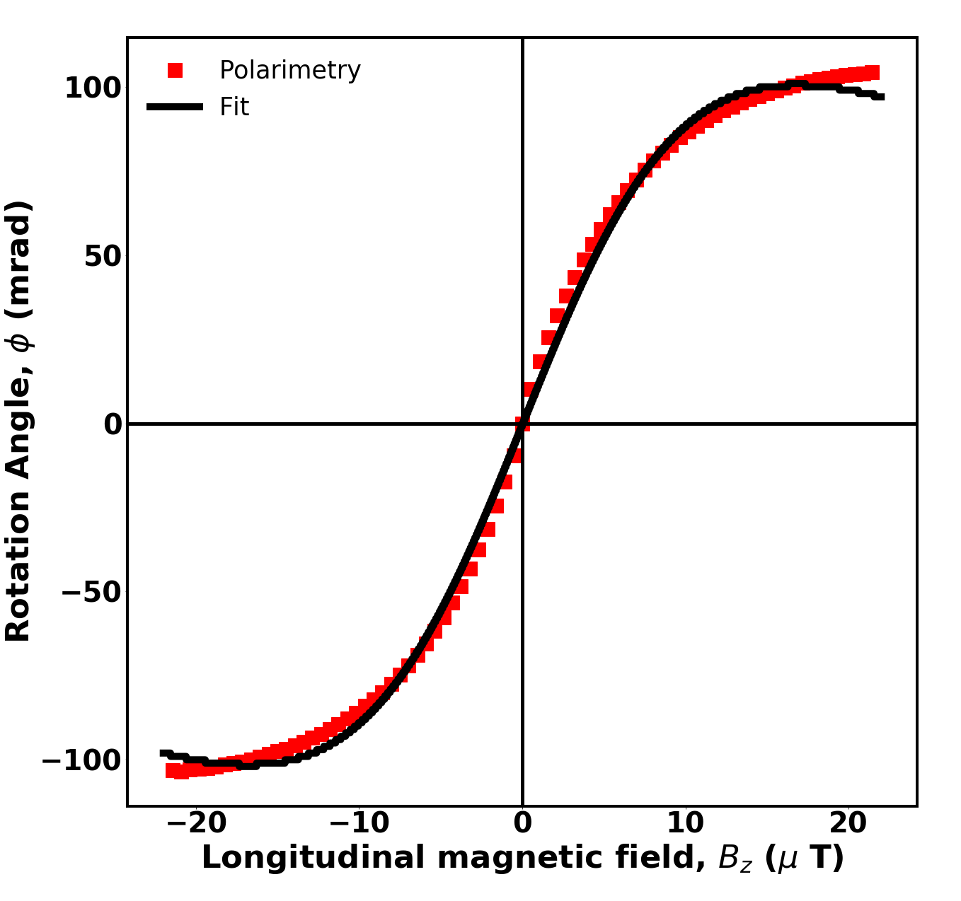
In the balanced polarimetry method, intensity of the horizontal (H) and vertical (V) linear polarization components of the light beam propagating through the medium are measured simultaneously using two photo-detectors and the magneto-optical rotation, for small rotations is calculated using the formula, , where and are the intensity of horizontal and vertical polarization components respectively. The theoretically achievable detection sensitivity in this scheme is limited by the photon shot-noise Grangier et al. (1987), which is calculated to be 46 for our experimental system. In our measurement (experiment schematic shown in FIG. 1 without the SBC), the state-of-polarization of the on-resonance light beam ( = 780nm) from the diode laser (Vantage 7100, NewFocus) entering the atomic medium (Rb) is kept fixed at 0.785 rad () with respect to using the polarizer P. The Rubidium cell is 7 cm long and 2.5 cm diameter and is placed on-axis within the solenoid coils surrounded by a 3-layer -metal shield and known longitudinal magnetic field is applied by passing current from a stabilized current source (Keithley 6221). The frequency of the laser is stabilized using saturation absorption spectroscopy Smith et al. (2008) to be at the D2 transition of Rb85 atoms. The laser beam is nearly coolimated with a power of 1mW over a beam diameter of 0.4cm, corresponding to beam intensity of 8mW/cm2 at the vapour cell. Light exiting the Rb cell passes through Glan-Taylor analyzer A whose transmission axis is parallel to , such that the horizontal component of polarization passes though it and falls on the photo-detector, PD1, while the vertical component is reflected and falls on the photo-detector PD2. In the absence of applied magnetic field, equal intensities are measured in the two photo-detectors (PD1, PD2), corresponding to zero magneto-optical rotation of the plane of polarization of light exiting the atomic medium. When the magnetic field is turned on, the plane of polarization of the linearly polarized light leaving the atomic medium rotates, resulting in slightly different intensities measured in the two detectors, giving rise to magneto-optical rotation signal calculated. Our experimental measurement is shown in Fig. 2, along with the fit using Eqn. 1 giving MHz and 0.2. The slope of the linear region near zero magnetic field is calculated to be 18.3 . From the slope, the sensitivity , of the magentometer is calculated to be 2.5 nT. However, upon close observation, it can be seen from FIG. 2 that even around zero magnetic field, one sees departure of the experimental data from the theoretical curve, indicating potential limitation of the balanced polarimetry method in measuring small rotation angles, corresponding to small value of applied magnetic field.
II.2 Weak Measurement Method
One of the objectives of this article is to demonstrate optical magnetometry using weak measurement method and its capability to measure polarization rotation angles and hence the applied magnetic field smaller than the measurable limit of the balanced polarimetry method. The high sensitivity of the weak measurement method used for obtaining the polarization rotation angle, is achieved via optical amplification based on the concept introduced by Aharonov et al. Aharonov et al. (1988) using the Stern-Gerlach device.
We use this concept implemented in classical systems Duck et al. (1989); Ritchie et al. (1991) for amplifying weak effects to measure small rotation in the state of polarization in response to applied magnetic field, leading to a large change in the Gaussian beam intensity profile. This is realized by coupling the state of polarization and the transverse momentum degree of freedom of the input Gaussian beam using a Soleil-Babinet compensator (SBC). Here we refer the state of polarization of the Gaussian beam as the observable and its transverse momentum vector with canonical conjugate transverse position as the apparatus. The SBC is used to couple the polarization state and the momentum vector resulting in inhomogeneously polarized Gaussian beam, also known as spin-orbit beam and has been used to measure weak optical chirality Suna and Viswanathan (2018); Samlan et al. (2018).
In our experimental setup shown in FIG. 1, the polarizer P pre-selects the state of polarization of the laser beam with Gaussian intensity profile to be at an angle with respect to . The transverse electric field of the pre-selected Gaussian beam is given by,
| (4) |
where is the beam waist and is the electric field amplitude. Passing through the Soleil-Babinet compensator (SBC) Born and Wolf (1997), a zero-order variable phase retarder, whose fast-axis is oriented at an angle with respect to results in the appearance of phase-polarization gradient across the paraxial Gaussian beam. The Jones matrix of the SBC can be written as,
| (5) |
where is the phase difference between the ordinary and extra-ordinary rays corresponding to the beam center, is the phase gradient across the beam cross-section and is the Rayleigh range. The analyzer A, post-selects the orthogonal polarization state, , resulting in transverse electric field,
| (6) |
where is the rotation matrix. A CMOS-camera measures the beam intensity profile after passing though the analyzer. When the analyzer is oriented nearly orthogonal () to the polarizer we measure minimum output intensity and a two-lobe pattern, resembling Hermite-Gaussian () mode at the detector. is the offset angle of the analyzer dialed to remove other phase contributions. The centroid of the intensity profile is calculated using
| (7) |
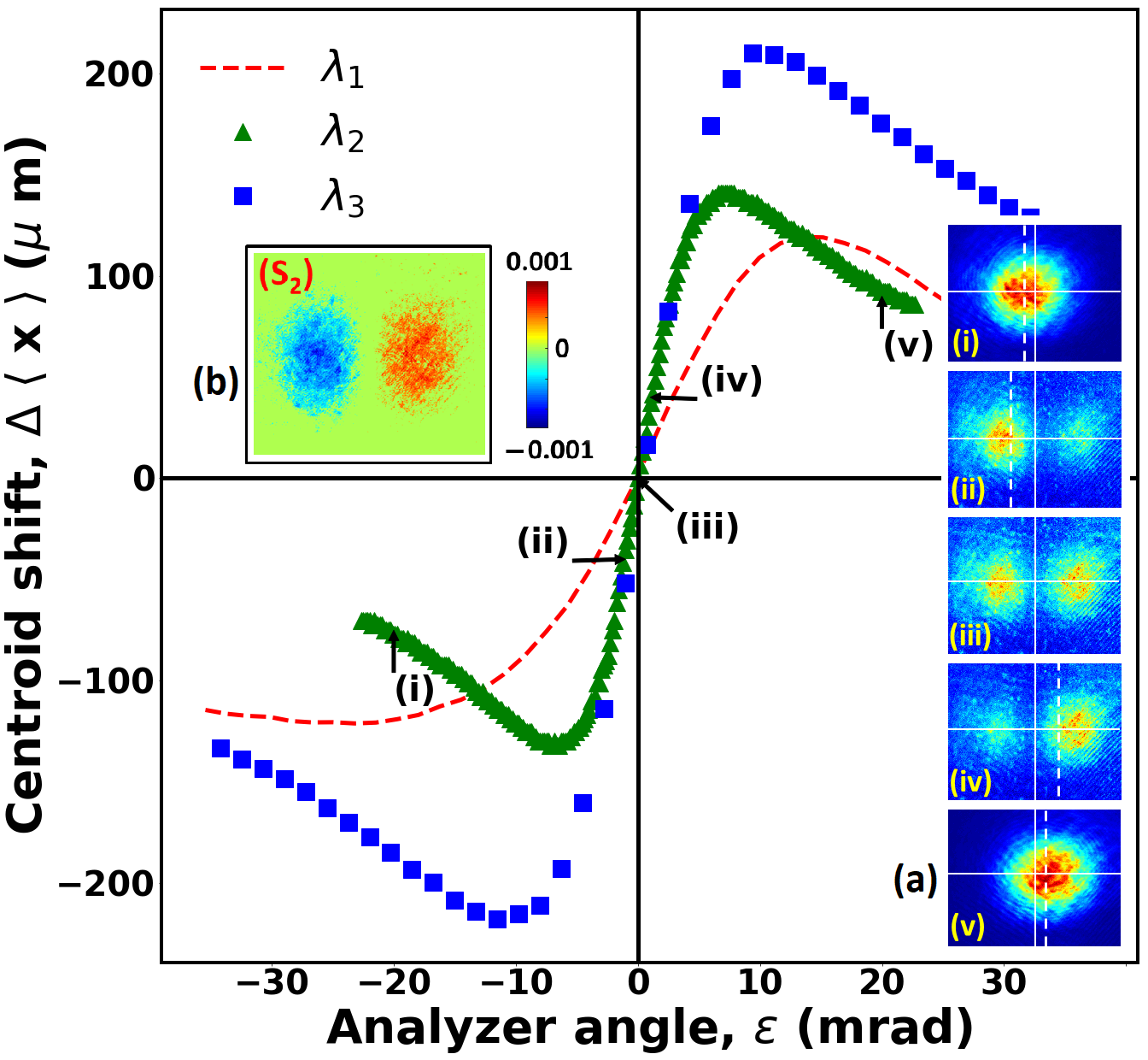
where is the beam intensity given by, . Changing the analyzer angle by a small amount from , will distort the beam profile at the detector from the mode 3. The resulting centroid shift, defined as (where is the x-coordinate of the beam centroid corresponding to angle ) is measured at various analyzer angle and for different SBC orientation and incident polarization as shown in FIG. 3. A calibration plot is made between the centroid shift and , which shows a linear behavior around the post-selected angle of the analyzer , shown in FIG. 3. The centroid shift was found to be zero for orthogonal polarizer-analyzer orientations. The optical beam generated by propagating through the SBC possesses phase gradient along the x-axis and is confirmed by measuring the Stokes parameter,Goldstein (2010). Inset in FIG. 3 shows the weak orientation value of the state of polarization of the two lobes of the HG mode indicating clearly the presence of phase-polarization gradient in the beam cross-section.
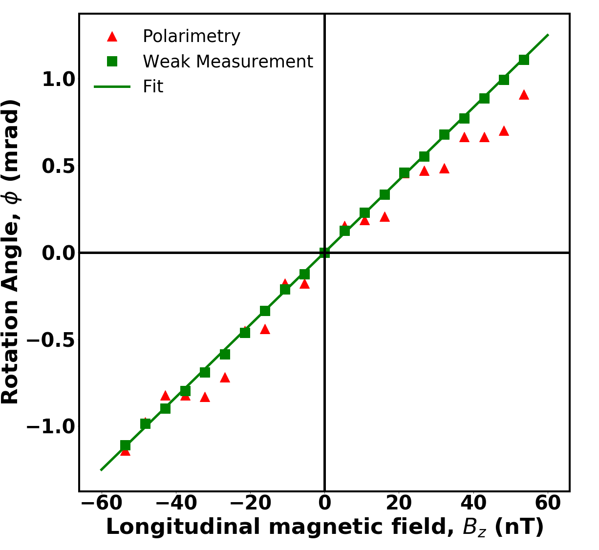
The linear portion of the beam centroid shift versus calibration plot is used to calculate the magneto-optical rotation of the plane of polarization of light exiting the atomic medium. When the analyzer is brought back to , in the absence of the magnetic field, the medium does not affect the state of polarization and we get a like mode at the CMOS detector. When the magnetic field is turned on, the plane of polarization of the Gaussian beam changes due to resonant light-atom interaction, leading to a change in the intensity structure of the output beam due to change in the post-selection state due to magneto-optical rotation. From the measured intensity profile, the centroid shift is calculated for various values of the applied magnetic field . The experiment was carried out with the SBC oriented at and for horizontally polarized input beam (). Without the Rb85 gas cell in the beam path, the analyzer performs post-selection process resulting in the calibration graph shown in Fig. 3 (green triangle plot, with the slope of linear region = ). However, the introduction of Rb85 cell in the magnetic field, with the analyzer kept fixed at the crossed position results in a change in the behavior of the output mode pattern due to magneto-optical rotation by angle . The resulting beam centroid shift is used to calculate the optical rotation angle. It is to be noted that for the present case. Using the linear region of the calibration graph shown in FIG. 3, corresponding to and , the magneto-optical rotation of the plane of polarization of light exiting the atomic medium with respect to the applied longitudinal magnetic field is calculated. The rotation angle with respect to longitudinal magnetic field measured using weak measurement method are shown in FIG. 4 along with the data from balanced polarimetry. The data from weak measurement is fitted with Eqn. 1 and the slope is found to be 20.8. One can easily see from the figure that the magneto-optical rotation measured using the weak measurement method does not show jumps due to resolution limitation like the balanced polarimetry method.
As can be seen from FIG. 3, the slope of the linear region of the graph and hence the sensitivity of the method depends on the ( and ) parameters of the SBC and can be tuned over a range of values. However, the highest achievable sensitivity to magneto-optical rotation by weak measurement is determined by the shot-noise limited centroid shift that can be measured, which is 0.56m for our detector, leading to a sensitivity in optical rotation, of 16 . From the slope for the weak measurement shown in FIG. 4 and , the sensitivity to the longitudinal magnetic field is calculated to be 0.8 nT. It is important to note that the range of rotation angle that we can measure using this method is limited to the linear region of the centroid shift. However, for measuring magnetic field corresponding to rotation beyond the linear region of the centroid shift, possible options will be to offset zero crossing and hence the measurement range by either applying a known dc field and / or rotating the analyzer angle to bring the detection to within the linear measurement range.
.
III Conclusion
We proposed and demonstrated weak measurement method for ultra-sensitive, single-beam atom-optical magnetometer whose sensitivity to magneto-optical rotation is given by, , where is the slope of centroid shift with respect to analyser angle and is the sensitivity to centroid shift measured by CMOS camera which is limited by photon shot noise of the camera. Unlike measurement of using balanced polarimetry method, which is totally photon shot noise dependent, in the weak measurement method we have an additional control, the slope of the centroid shift , to improve the sensitivity to magneto-optical rotation. It was observed that the slope increases with decreasing the relative angle between the fast axis of SBC and the initial state of polarization of the light beam, and the best slope measured is and the corresponding sensitivity is is 16 . Currently the magnetometer works in the non-linear Faraday regime, with a dynamic range of 0.5 T, and has sensitivity to longitudinal magnetic field of 1 nT. Employing SERF regime is expected to reduce to a few Hz, enhancing the magnetic field sensitivityLedbetter et al. (2008); Seltzer and Romalis (2009), by while reducing its dynamic range. Coupling this with increased sensitivity of the weak measurement technique, better sensitivity of the order of f T can be achieved. The weak measurement method is a compact single beam dc technique that does not involve any modulation in optical magnetometers, making it very useful over a broad band spectral range for optical magnetic sensors especially the compact, MEMSKnappe et al. (2016); Sheng et al. (2017) sensors, complimenting other modulation and radio frequency based techniques.
Acknowledgement
RRS thanks UGC-RGNF for research fellowship, NKV thanks Science and Engineering Research Board (SERB), Department of Science and Technology (DST), India for continued financial support to this area of research, GR thanks Defense Research and Development Organisation, India for financial assistance. One of the authors, RRS passed away under unfortunate circumstances in the final stages of this work and this article is dedicated to his memory.
References
References
- Budker et al. (2002a) D. Budker, W. Gawlik, D. F. Kimball, S. M. Rochester, V. V. Yashchuk, and A. Weis, Rev. Mod. Phys. 74, 1153 (2002a).
- Budker and Romalis (2007) D. Budker and M. Romalis, Nature Physics 3 (2007), 10.1038/nphys566.
- Taylor et al. (2008) J. M. Taylor, P. Cappellaro, L. Childress, L. Jiang, D. Budker, P. R. Hemmer, A. Yacoby, R. Walsworth, and M. D. Lukin, Nature Physics 4 (2008), 10.1038/nphys1075.
- Dang et al. (2010) H. B. Dang, A. C. Maloof, and M. V. Romalis, Applied Physics Letters 97, 151110 (2010), https://doi.org/10.1063/1.3491215 .
- Fan et al. (2018) T. Fan, L. Zhang, X. Yang, S. Cui, T. Zhou, and Y. Feng, Opt. Lett. 43, 1 (2018).
- Macaluso and Corbino (1898) D. Macaluso and O. M. Corbino, Nuovo Cimento 8, 257 (1898).
- Macaluso and Corbino (1899) D. Macaluso and O. M. Corbino, Nuovo Cimento 9, 384 (1899).
- Budker and Kimball (2013) D. Budker and D. F. J. Kimball, eds., Optical Magnetometry, 1st ed. (Cambridge University Press, 2013).
- Bennett (1962) W. R. Bennett, Phys. Rev. 126, 580 (1962).
- Budker et al. (2002b) D. Budker, D. F. Kimball, S. M. Rochester, and V. V. Yashchuk, Phys. Rev. A 65, 033401 (2002b).
- Budker et al. (1998) D. Budker, V. Yashchuk, and M. Zolotorev, Phys. Rev. Lett. 81, 5788 (1998).
- Budker et al. (2000) D. Budker, D. F. Kimball, S. M. Rochester, V. V. Yashchuk, and M. Zolotorev, Phys. Rev. A 62, 043403 (2000).
- Allred et al. (2002) J. C. Allred, R. N. Lyman, T. W. Kornack, and M. V. Romalis, Phys. Rev. Lett. 89, 130801 (2002).
- Pustelny et al. (2006) S. Pustelny, D. F. Jackson Kimball, S. M. Rochester, V. V. Yashchuk, W. Gawlik, and D. Budker, Phys. Rev. A 73, 023817 (2006).
- Gawlik et al. (2006) W. Gawlik, L. Krzemień, S. Pustelny, D. Sangla, J. Zachorowski, M. Graf, A. O. Sushkov, and D. Budker, Applied Physics Letters 88, 131108 (2006), https://doi.org/10.1063/1.2190457 .
- Grangier et al. (1987) P. Grangier, R. E. Slusher, B. Yurke, and A. LaPorta, Phys. Rev. Lett. 59, 2153 (1987).
- Smith et al. (2008) J. A. Smith, X. Chu, W. Huang, A. J. Wiig, and A. Brown, Optical Engineering 47, 47 (2008).
- Aharonov et al. (1988) Y. Aharonov, D. Z. Albert, and L. Vaidman, Phys. Rev. Lett. 60, 1351 (1988).
- Duck et al. (1989) I. M. Duck, P. M. Stevenson, and E. C. G. Sudarshan, Phys. Rev. D 40, 2112 (1989).
- Ritchie et al. (1991) N. W. M. Ritchie, J. G. Story, and R. G. Hulet, Phys. Rev. Lett. 66, 1107 (1991).
- Suna and Viswanathan (2018) R. R. Suna and N. K. Viswanathan, Opt. Lett. 43, 4337 (2018).
- Samlan et al. (2018) C. T. Samlan, R. R. Suna, D. N. Naik, and N. K. Viswanathan, Applied Physics Letters 112, 031101 (2018), https://doi.org/10.1063/1.5008732 .
- Born and Wolf (1997) M. Born and E. Wolf, Principles of optics: electromagnetic theory of propagation, interference and diffraction of light (Cambridge University Press, 1997).
- Goldstein (2010) D. H. Goldstein, Polarized Light, 3rd ed. (CRC Press, 2010).
- Ledbetter et al. (2008) M. P. Ledbetter, I. M. Savukov, V. M. Acosta, D. Budker, and M. V. Romalis, Phys. Rev. A 77, 033408 (2008).
- Seltzer and Romalis (2009) S. J. Seltzer and M. V. Romalis, Journal of Applied Physics 106, 114905 (2009), https://doi.org/10.1063/1.3236649 .
- Knappe et al. (2016) S. Knappe, O. Alem, D. Sheng, and J. Kitching, Journal of Physics: Conference Series 723, 012055 (2016).
- Sheng et al. (2017) D. Sheng, A. R. Perry, S. P. Krzyzewski, S. Geller, J. Kitching, and S. Knappe, Applied Physics Letters 110, 031106 (2017), https://doi.org/10.1063/1.4974349 .