Navigation in the Presence of Obstacles
for an Agile Autonomous Underwater Vehicle
Abstract
Navigation underwater traditionally is done by keeping a safe distance from obstacles, resulting in “fly-overs” of the area of interest. Movement of an autonomous underwater vehicle (AUV) through a cluttered space, such as a shipwreck or a decorated cave, is an extremely challenging problem that has not been addressed in the past. This paper proposes a novel navigation framework utilizing an enhanced version of Trajopt for fast 3D path-optimization planning for AUVs. A sampling-based correction procedure ensures that the planning is not constrained by local minima, enabling navigation through narrow spaces. Two different modalities are proposed: planning with a known map results in efficient trajectories through cluttered spaces; operating in an unknown environment utilizes the point cloud from the visual features detected to navigate efficiently while avoiding the detected obstacles. The proposed approach is rigorously tested, both on simulation and in-pool experiments, proven to be fast enough to enable safe real-time 3D autonomous navigation for an AUV.
I Introduction
This paper addresses the problem of trajectory planning for underwater structure inspection and mapping. Underwater structure mapping is an important capability applicable to multiple domains: marine archaeology, infrastructure maintenance, resource utilization, security, and environmental monitoring. While the proposed approach is not limited to the underwater domain, this work addresses the challenging conditions encountered underwater, with a special focus on shipwreck mapping. Underwater mapping has traditionally focused on acoustic sensors [1, 2, 3, 4]. However, most inspections require visual input [5, 6, 7]. The state-of-the-art in autonomous operations is to observe the target structure from far enough to avoid navigation in cluttered spaces, while remotely controlled operations present entanglement hazards. As a result, most inspections suffer from gaps due to occlusions, and low-resolution due to the water effects on the camera sensor. The presented work enables autonomous operations underwater close to the structure to be inspected; before this was only partially possible with teleoperation.
Maps of underwater structures such as wrecks, caves, dams, and docks are often available either through acoustic sensing [8] or via photogrammetry [9, 10]. In this paper we present an augmentation of Trajopt [11], a popular path-optimization open source package for (mobile) manipulators, to facilitate 3D trajectory planning of an AUV utilizing either a known map or an online constructed local map. The proposed method is realized on an Aqua2 vehicle [12]. The Trajopt planner is augmented with a sampling-based correction scheme that resolves the local minima problem. Furthermore, different map representations were tested including geometric primitives and point-cloud implementations.
Fast motion planners, such as KPIECE [13], use physics-based simulators to plan with kinodynamic constraints and can solve the planning problem for systems with non-trivial dynamics. While previous work [14, 15, 16] provided an analysis of the dynamics of the Aqua vehicle, the model is still inaccurate and moreover, the on-board computing resources do not allow for utilizing a physics-based simulator online.
The proposed method was rigorously tested in simulation and in the pool. Utilizing the Gazebo simulator [17] with an underwater extension that emulates the kinematic behaviour of the Aqua2 vehicle, the tested environments demonstrated changes in depth, and attitude in three dimensions for realizing the produced trajectories. Furthermore, tests at an indoor diving pool, with various obstacle setups, verified the validity of the proposed approach.
The proposed approach provides contributions in two conceptual areas: path planning of mobile robots in 3D and underwater navigation in cluttered environments. More specifically, we augmented the Trajopt package enabling operations of an autonomous mobile robot in three dimensions. We introduced a fast warm-starting method to avoid local minima issues using an RRT-based approach. Furthermore, we demonstrated the use of Trajopt for online planning based on convex decomposition of unordered point clouds. The proposed framework enabled underwater operations in cluttered spaces. In particular, a light-weight geometric navigation framework utilizing the full 3D motion capabilities of the Aqua2 AUV, enabled operations with a known map, or in unknown areas of cluttered underwater environments. Autonomous operations of real-time planning and replanning in conjunction with visual inertial state estimation in environments of substantial complexity, even without utilizing a known hydro-dynamics model.
II Related Work
In environments with complex dynamics, such as underwater, one of the main challenges is to generate safe paths. Several methods have been explored to correct the deviations caused by inertia and currents, including the FM* planning system [18]. Other methods rely on observations about the structure of the terrain [19] and satellite imagery [20] to estimate the effects of currents. Genetic algorithms [21] and mixed integer linear programming approaches [22] have also been used to support the computation of paths in dynamic underwater environments.
The work of Hernandez et al. [23] provided an online sampling based framework for an AUV in 3D, accounting also for the dynamics of the system. The proposed framework although was shown to be capable to work in real-time, it needed close to half a minute for producing solutions with clearance guarantees. Moreover, during the online experiments the replanning was close to 1Hz but the robot was constrained to a constant depth reducing the planning space to 2D. When accounting for currents, other studies [24, 25] utilize sampling-based techniques and a complete dynamic model of the AUV, but are only shown to work in uncluttered environments with few obstacles.
Another challenge in underwater path planning is to generate paths rapidly enough to be able to compute and execute them online. Green and Kelly demonstrated a branching-based method for quickly generating safe paths in a 2D environment [26] which has since been the basis of several optimizations [27, 28, 29, 30]. Path planning has also been optimized by reducing many candidate paths to equivalence classes [31].
Though optimal sampling-based techniques [32, 33, 34, 35] provide near-optimal solutions and have improved over time, they, in general, require more computational resources, more time, and often an exhaustive search of the configuration space. Some studies on online underwater navigation with sampling-based techniques quickly generate safe paths, however, they are limited to 2D motions [36] or require additional assumptions regarding the vertical relief [37] without exploiting the full potential of available 3D motions.
In some applications, it is necessary for AUVs to navigate in an environment without global knowledge of the environment. In such cases, obstacles are observed, often by stereo vision as has been done on aerial vehicles [38]. Exploration of an unknown environment by aerial vehicles has been performed using a 3D occupancy grid using probabilistic roadmaps (PRM) and the D* Lite algorithm for planning [39]. Although underwater and aerial domains provide different challenges, both require path planning in 3D. For an AUV such as Aqua2, whose movements do not correlate exactly with control inputs, planning becomes even more difficult. Other AUVs have also been used for path planning, such as RAIS [40] and DeepC [41]. Another AUV, REMUS [42], used obstacle avoidance specifically for exploration of shallow waters.
The Aqua2 AUVs have a variety of swimming gaits in order to enable tasks such as swimming in a straight line, on the side, in a corkscrew motion, or performing a barrel roll [43]. Visual tags were used to enable the AUV to navigate over structures [44]. Furthermore, the robot learned a reactive controller for navigating over the coral reef while maintaining a safe distance [45, 46].
III Proposed Approach
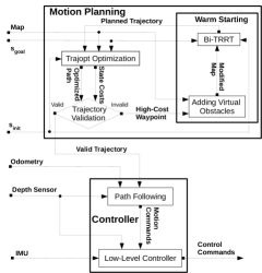
The objective of this paper is to develop algorithms that enable the Aqua2 robot to navigate reliably and safely through a dense field of obstacles, given start and goal poses and . Figure 2 presents an overview of the proposed system.
III-A System Overview
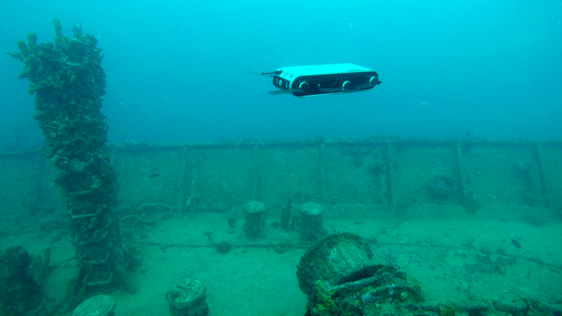
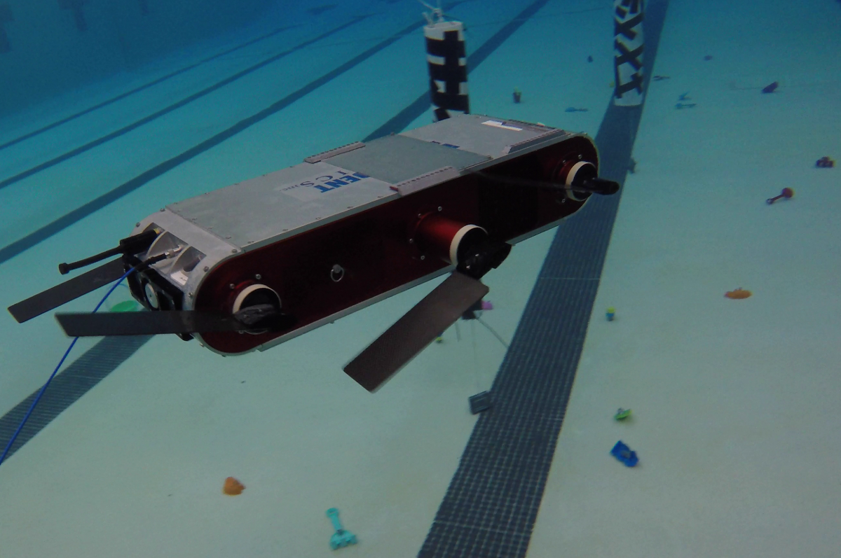
The target system is the Aqua2 amphibious platform [47], pictured in Figure 1. In its aquatic configuration, Aqua2 uses the motion from six flippers, each independently actuated by an electric motor, to swim. Aqua2 has 6 degrees of freedom, of which five are controllable: two directions of translation (forward/backward and upward/downward), along with roll, pitch and yaw.
The robot’s primary sensing modality is vision. It is equipped with three iDS USB 3.0 UEye cameras: two facing forward and one in the back. The front-facing cameras are used for navigation and data collection. In addition to these cameras, Aqua2 also has an IMU and a pressure sensor which are used for controlling the motions and can be utilized for visual-inertial state estimation [48, 49, 50, 51]. The fields of view of the cameras are 120 degrees (horizontal) and 90 degrees (vertical) tilted downward by 40 degrees from the horizontal plane.
III-B Trajectory Planning
Motion planning in this context must balance several competing constraints, including the need for efficiency, the possible need to replan, and the limited computational power available on the robot (particularly when one considers the other essential tasks of perception, mapping, etc.). In addition, because of its complex —yet not readily modeled— dynamics and kinematics combined with the unpredictable nature of maritime currents, the system is quite susceptible to disturbances. Thus, the planner should provide solutions that satisfy some minimum clearance to avoid collisions.
To satisfy this challenging trade-off, the proposed system utilizes an optimization-based planning approach. Specifically, the implementation uses Trajopt [11], which has been proven as a very robust method for manipulators and mobile manipulators in 2D. It is computationally efficient and takes into account not only the states but the complete path between them using the transition between states, contrary to alternatives such as CHOMP [52] and STOMP [53]. To the best of authors’ knowledge, Trajopt has not yet been used for 3D motion planning for mobile robots, nor in the underwater domain, in the past.
The main idea behind Trajopt is to represent the path from to as an ordered list of waypoints, each of which is a pose for the robot. Starting from an initial set of waypoints —generally based on the linear interpolation between and — Trajopt forms a convex optimization program, in which each degree of freedom of each waypoint is a variable, the obstacles are encoded as constraints, and the objective is to minimize a weighted form of the path length. An important advantage is that, because of this general form, one can insert additional content-specific constraints, such as a maximum depth.
III-B1 Input Methods
Trajopt optimizes the distance between the swept-out volumes of the robot’s trajectory and the obstacles; as shown in Figure 3. For efficiency, Trajopt expects the map to be stored in a form where the normal vectors between the robot’s body and the obstacles can be extracted rapidly. One geometric method for presenting the obstacles to Trajopt, suitable in cases where the environment is well-known, consists of specifying the obstacle shapes and locations as instances of a set of built-in primitives, typically as rectangular boxes.
We also implemented a version that utilizes a point cloud input representation, which can be produced directly from raw sensor data. First, the point cloud is provided as input to the fast surface reconstruction algorithm of Zoltan et al. [54]. Then, the algorithm approximates the produced mesh via a collection of convex polytopes which can be directly processed by the Trajopt optimizer.
III-B2 Constraints
The objective function is parameterized by coefficients for the path length and the obstacle avoidance and by a distance parameter , measuring the maximum distance from the obstacles where the cost will be applied. These parameters required tuning for the underwater environment and the AUV used; Section IV describes the specific values utilized in our experiments.
Our system employs an additional term in the cost to ensure that the robot will not reach the surface, and will remain entirely underwater. The cost function was applied on the coordinate of all the states , where , and defined as follows:
| (1) |
where . Assuming that on the surface , the condition in Equation 1 penalizes every state above ensuring that the robot will remain underwater, accounting also for potential inaccuracies in control.
III-C Overcoming Local Minima
A problem that many optimization-based motion planners, including Trajopt, face is the possibility that the optimization may converge to a local minimum. Though generally rare in the implemented system, this situation can present a safety hazard for the robot, because the completed path may not necessarily maintain safe distance from the obstacles. Local minima can be present, for example, either (a) when the path is passing through an obstacle and there is no free space in a radius, or (b) when the path is passing through a narrow passage and the desired clearance from the obstacles cannot be maintained.
Typically, such issues are resolved with warm-starting of the optimization process: a fast motion planner is used to generate beforehand a set of valid paths and these paths are used consecutively to initialize the optimization until a valid solution is found. An example of such work [55] for Trajopt uses the BiT-RRT [56] planner.
We propose the following novel iterative warm-starting approach, using BiT-RRT [56], by inserting virtual obstacles into the planning process. The optimization step works with the motion planner in the following manner:
-
1.
The optimization result is checked and in case of failure, the waypoint with the highest cost is selected.
-
2.
The map used by the motion planner is altered by adding a virtual obstacle of size in the position of that waypoint.
-
3.
The planner plans a path avoiding the new high cost area of local minimum with a smaller than distance from obstacles during collision checks.
-
4.
The new path is used to initialize the path optimization process and the procedure continues if needed.
This process forces the planner to identify an alternative path that avoids the most problematic portion, in terms of the cost function, of the previous path.
III-D Trajectory Following
III-D1 Localization
The problem of underwater localization has proven to be extremely challenging [57, 58] due to the lighting variations, hazing, and color loss [59]. We tested two solution strategies for this problem.
Primitive Estimator
A primitive estimator has been employed using the depth sensor, the attitude estimation from the IMU and the expected forward speed of the AUV (based on the swimming pattern utilized). Though subject to drift over long distances, this estimator has guided the Aqua2 vehicles for a variety of basic maneuvers and swimming patterns. During operations with a known map, this primitive estimator is utilized to track the planned trajectory.
SVIn
During operations in an unknown environment, more accurate localization may be useful, in addition to the required ability to detect nearby obstacles. Visual Inertial state estimation, introduced by Rahman et al. [51] and later extended to utilize depth measurements and loop-closures [60], is used for simultaneously localizing and mapping nearby obstacles. The resulting point-cloud produced by SVIn enables the AUV to navigate safely around obstacles.
III-D2 Waypoint seeking
The optimization stage of the proposed pipeline produces in a timely manner a path , as an ordered set of consecutive goal states that should be sequentially achieved by the robot. A linear PD controller proposed by Meger et al. [44] is utilized, which employs the IMU and the depth sensor data. This closed-loop controller accepts commands in the form:
| (2) |
in which is the desired forward linear velocity, is the desired heave (that is, upward or downward linear velocity), is the desired depth to reach and the desired orientation for the robot to move in the world frame. The current framework, for simplicity considers only purely forward motion setting .
The PD controller controls the desired depth by linear interpolation. Assuming that the current state of the robot is and the current goal position is in the world frame, to guarantee smooth transitions that are bounded inside the calculated safe swept-out volumes of the optimization stage, the desired depth is calculated as
| (3) |
where is the depth of the previous achieved goal (base case ), the depth of the current goal, and is the current measured depth. The idea is to ensure the linear change of depth from one position to the other and ensure linear transitions similar to the ones assumed by Trajopt.
Regarding the desired orientation, the pitch is adjusted automatically from the desired depth and the roll does not affect the direction of the motion, thus only the computation of the desired yaw is needed, with respect to the translation error . Given the position of the robot, the yaw changes in such a way that the AUV will always move towards facing the goal.
Lastly, assuming the possible deviation is bounded by for a given speed and that the optimization was successful, the AUV should safely navigate from one goal to the next one. As a result of the above, given a threshold of , the goal is declared reached, if the error is less than and a local minimum is detected, since otherwise the robot will be sliding away due to disturbances.
IV Experimental Results
Extensive experiments were performed using the Gazebo simulator, and in numerous deployments of the Aqua2 AUV at two pools in our university, a shallow swimming pool of dimensions and a deep diving pool of dimensions . The main objective of the various experiments was to demonstrate the reliable navigation functionality of Aqua2 using the proposed framework. In all of the experiments the AUV had a constant speed of — the expected operational speed — and a bounded motion with a minimum obstacle avoidance distance of . Obstacle avoidance and path length coefficients were adjusted to relatively high values and , respectively, favoring safety over path length optimality, while the number of waypoints was determined either by the distance from the current position to the goal — placing a state every — or by the number of states provided by the Trajopt planner. The experiments tested planning on a known map, with a focus on efficient trajectories, and online, using the camera for obstacle avoidance and frequent replanning.
IV-A Known Map — Offline Planning
During planning with a known map, the input map was a set of geometric primitives (planes, boxes, cylinders, etc.) and the iterative warm-starting process was used. All plans were produced in less than half a second.
IV-A1 Simulated Environment
Two different environments are presented here highlighting different challenges for Trajopt. In the first environment, called the Window environment, two rooms, separated by a wall with an opening (window) between them and open to one side demonstrates path optimality; see Figure 4. The original path results in a local minimum. After the iterative warm-starting method is used the solution through the window is found. Furthermore, for this experiment the AUV has to keep a horizontal pose during motions that causes larger drifting from inertia. For this purpose, in this single case we increased to .
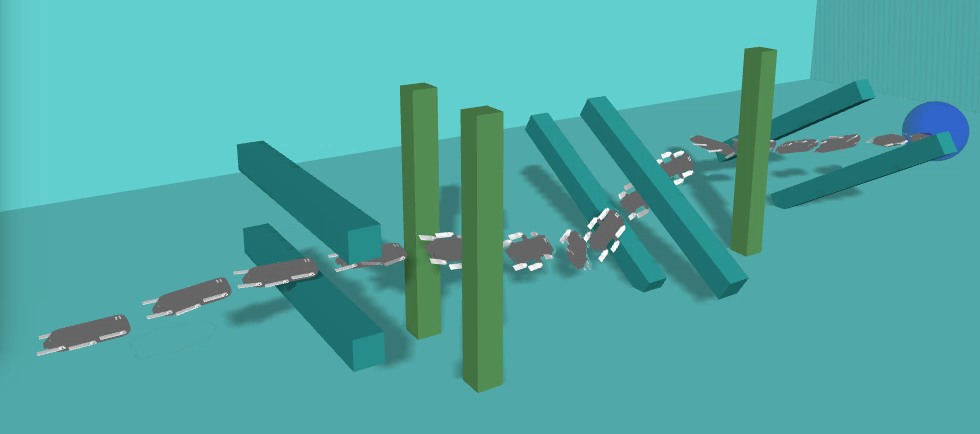
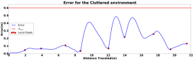
The second environment, called the Cluttered environment, focuses more on the capability of our method, inherited from Trajopt, to minimize oscillation while passing through a sequence of obstacles that need accurate motions with fast orientation changes; see Figure 4. In this environment not only was the roll adjusted during optimization adapting to the motion, but also the Aqua2 is guided to pass in a parallel motion between each pair of pillars, thus maximizing the distance from both of them, for increased safety.
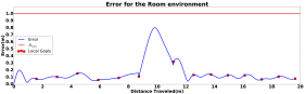
Safe navigation for the Aqua2 is achieved only if during the motion the trajectory following method does not violate the assumed clearance by the planning process. For these challenging scenarios, where the robot changes orientations fast, the oscillations are shown in Figure 6. The error at time , , is calculated as the Euclidean distance of the measured simulation odometry , to the line formed by the previous and the current local goal :
| (4) |
IV-A2 Real
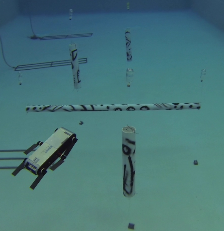
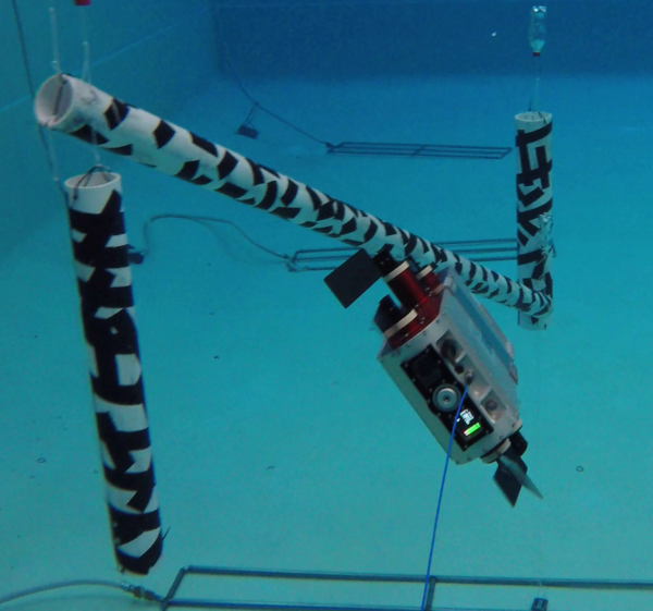
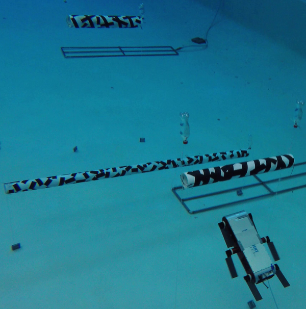
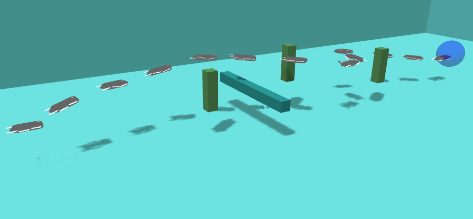
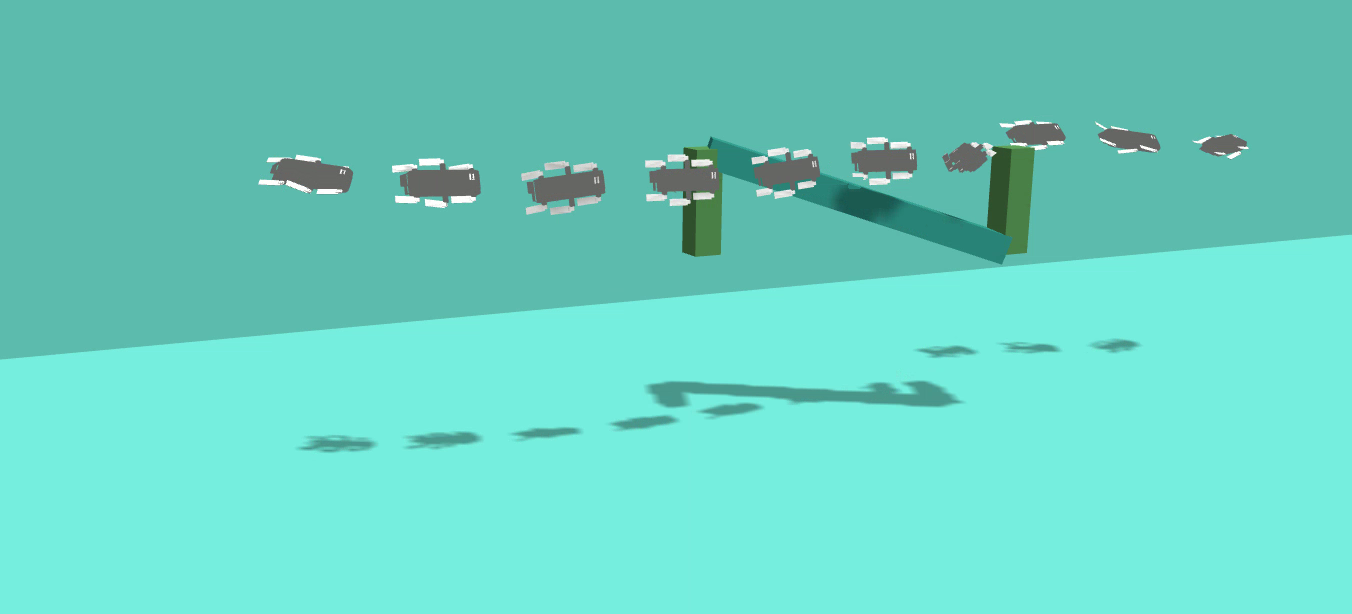
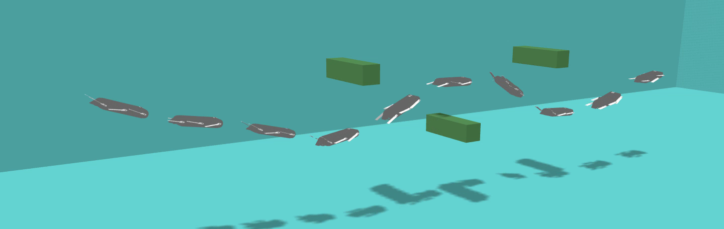
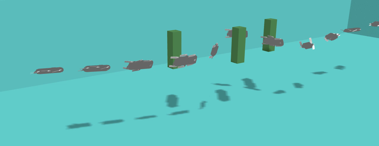
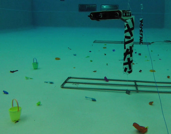
Four different environments were used at the two pools in our university, demonstrating operations with the Aqua2 AUV; see Figure 5. The placement of the obstacles followed the created map used as input to the augmented Trajopt planner. In the first environment, the Aqua2 was forced to maintain an attitude facing the floor, a situation that maximizes drift during yaw changes. The robot was able to successfully avoid all the obstacles and quickly self-correct its orientation; see Figure 5 for a image of the AUV during operations and Figure 5 for an overview of the trajectory. For the other three environments, the attitude of the AUV was optimized by the planner. In the second environment the robot avoided the two vertical pipes and passed over the diagonal one; see Figure 5(b),(f). Three horizontal pipes were used to force the AUV in continuous depth changes; see Figure 5(c),(g). Finally, three vertical pipes resulted again in obstacle avoidance with a roll at ; see Figure 5(d),(h).
IV-B Sensor based Planning — Online
The deployment of the proposed framework online highlighted some computational challenges. First, the state estimation consumes a large fraction of the computing resources. Second, the most computationally expensive component of the motion planning pipeline is the convex decomposition step, using approximately of the total planning time. For efficiency, the convex decomposition parameters were adjusted to produce many small convex polyhedra, instead of a few large ones. A history of the observations was kept to account for the limited field of view of the AUV. In all cases the replanning frequency was on average at 1Hz.
IV-B1 Simulated Environment
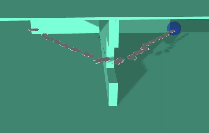
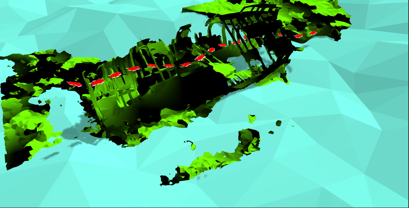
The model “Shipwreck, Hooe Lake, Plymouth” from Sketchfab111http://sketchfab.com/ was simplified and used in the Gazebo simulator. For computational efficiency, no texture was used in the simulator and the basic point-cloud was acquired from the model using a resolution of points. The AUV was guided through the inside of the shipwreck, while avoiding the observed obstacles; see Figure 7. The complex environment presented in Figure 4 was used for online navigation resulting in similar results.
IV-B2 Real
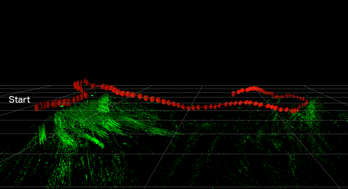
Additional real pool experiments were conducted using state estimation from the robust underwater SLAM package SVIN [60] with additional sand-toys weighted and placed on the floor to improve the odometry estimation together with obstacles to test obstacle avoidance; see Figure 8. The same configuration was used with the online simulation framework with the difference that the AUV was constrained at constant depth to maintain tracking using the features on the floor. The two environments, at the shallow and deep pool, used two vertical obstacles resulting in similar obstacle avoidance trajectories. Figure 8 presents the overall recorded trajectory and features detected from SVIn [60]. During one of the experiments the AUV’s motion brought it towards a diver recording the experiment, who, to the diver’s relief, was treated as another obstacle and was avoided.
V CONCLUSIONS
This paper demonstrated novel capabilities for underwater navigation through cluttered spaces. The proposed framework was able to plan and successfully execute efficient trajectories, while avoiding obstacles and taking into account the kinematic constraints of the vehicle, in both known and unknown environments. Numerous simulations highlighted the abilities of this agile platform to navigate in narrow spaces. Experiments at the pool demonstrated the feasibility of the proposed method and highlighted challenge.
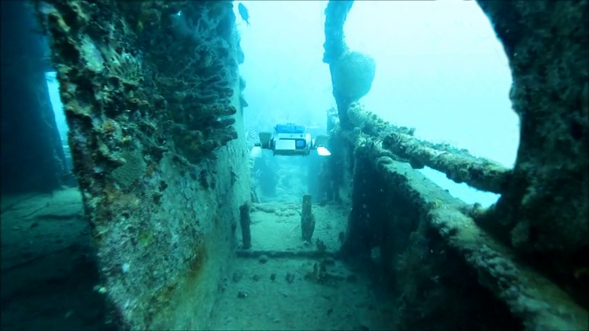
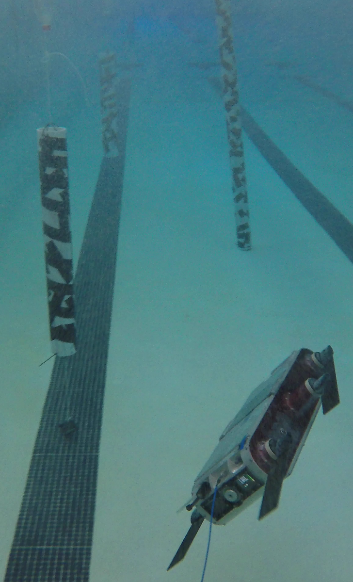
The presented results, combined with recent advancements in the robustness of underwater state estimation [61] and with new advanced gaits for the Aqua2 vehicles [43], will enable future autonomous exploration of environments not previously accessible to robots, such as shipwrecks and caves. For example, Figure 9 presents an enclosed environment at the Pamir shipwreck near Barbados, for which no prior map exists. In the past, an AUV was deployed there to perform a simple straight line transect. Future work will test the proposed approach in deployments to more fully explore such environments.
References
- [1] M. Gary, N. Fairfield, W. C. Stone, D. Wettergreen, G. Kantor, and J. M. Sharp, Jr, “3d mapping and characterization of sistema zacatón from depthx (de ep p hreatic th ermal e x plorer),” in Sinkholes and the Engineering and Environmental Impacts of Karst, 2008, pp. 202–212.
- [2] H. Johannsson, M. Kaess, B. Englot, F. Hover, and J. Leonard, “Imaging sonar-aided navigation for autonomous underwater harbor surveillance,” in 2010 IEEE/RSJ International Conference on Intelligent Robots and Systems. IEEE, 2010, pp. 4396–4403.
- [3] P. V. Teixeira, F. S. Hover, J. J. Leonard, and M. Kaess, “Multibeam data processing for underwater mapping,” in 2018 IEEE/RSJ International Conference on Intelligent Robots and Systems (IROS). IEEE, 2018, pp. 1877–1884.
- [4] R. Przeslawski, S. Foster, J. Monk, T. Langlois, V. Lucieer, and R. Stuart-Smith, “Comparative assessment of seafloor sampling platforms. report to the national environmental science programme,” 2018.
- [5] A. Abadie, P. Boissery, and C. Viala, “Georeferenced underwater photogrammetry to map marine habitats and submerged artificial structures,” The Photogrammetric Record, vol. 33, no. 164, pp. 448–469, 2018.
- [6] P. Drap, “Underwater photogrammetry for archaeology,” in Special Applications of Photogrammetry. IntechOpen, 2012.
- [7] W. Figueira, R. Ferrari, E. Weatherby, A. Porter, S. Hawes, and M. Byrne, “Accuracy and precision of habitat structural complexity metrics derived from underwater photogrammetry,” Remote Sensing, vol. 7, no. 12, pp. 16 883–16 900, 2015.
- [8] J. J. Leonard and H. F. Durrant-Whyte, Directed sonar sensing for mobile robot navigation. Springer Science & Business Media, 2012, vol. 175.
- [9] F. Menna, E. Nocerino, and F. Remondino, “Photogrammetric modelling of submerged structures: influence of underwater environment and lens ports on three-dimensional (3d) measurements,” In latest developments in reality-based 3D surveying and modelling, MDPI, Basel, Switzerland, pp. 279–303, 2018.
- [10] P. Agrafiotis, G. I. Drakonakis, D. Skarlatos, and A. Georgopoulos, “Underwater image enhancement before three-dimensional (3d) reconstruction and orthoimage production steps: Is it worth,” Latest Developments in Reality-Based 3D Surveying and Modelling; Remondino, F., Georgopoulos, A., González-Aguilera, D., Agrafiotis, P., Eds, 2018.
- [11] J. Schulman, J. Ho, A. X. Lee, I. Awwal, H. Bradlow, and P. Abbeel, “Finding locally optimal, collision-free trajectories with sequential convex optimization,” in Robotics: science and systems, vol. 9, no. 1. Citeseer, 2013, pp. 1–10.
- [12] G. Dudek, M. Jenkin, C. Prahacs, A. Hogue, J. Sattar, P. Giguere, A. German, H. Liu, S. Saunderson, A. Ripsman, S. Simhon, L. A. Torres-Mendez, E. Milios, P. Zhang, and I. Rekleitis, “A visually guided swimming robot,” in IEEE/RSJ International Conference on Intelligent Robots and Systems (IROS), Edmonton AB, Canada, Aug. 2005, pp. 1749–1754.
- [13] I. A. Şucan and L. E. Kavraki, “Kinodynamic motion planning by interior-exterior cell exploration,” in Algorithmic Foundation of Robotics VIII. Springer, 2009, pp. 449–464.
- [14] C. Georgiades, M. Nahon, and M. Buehler, “Simulation of an underwater hexapod robot,” Ocean Engineering, vol. 36, no. 1, pp. 39–47, 2009.
- [15] P. Giguere, C. Prahacs, and G. Dudek, “Characterization and modeling of rotational responses for an oscillating foil underwater robot,” in 2006 IEEE/RSJ International Conference on Intelligent Robots and Systems. IEEE, 2006, pp. 3000–3005.
- [16] N. Plamondon and M. Nahon, “Trajectory tracking controller for an underwater hexapod vehicle,” in OCEANS 2008. IEEE, 2008, pp. 1–8.
- [17] N. Koenig and A. Howard, “Design and use paradigms for gazebo, an open-source multi-robot simulator,” in 2004 IEEE/RSJ International Conference on Intelligent Robots and Systems (IROS)(IEEE Cat. No. 04CH37566), vol. 3. IEEE, 2004, pp. 2149–2154.
- [18] C. Petres, Y. Pailhas, P. Patron, Y. Petillot, J. Evans, and D. Lane, “Path planning for autonomous underwater vehicles,” IEEE Transactions on Robotics, vol. 23, no. 2, pp. 331–341, 2007.
- [19] S. Williams, G. Dissanayake, and H. Durrant-Whyte, “Towards terrain-aided navigation for underwater robotics,” Advanced Robotics, vol. 15, no. 5, pp. 533–549, 2001.
- [20] B. Garau, M. Bonet, A. Alvarez, S. Ruiz, and A. Pascual, “Path planning for autonomous underwater vehicles in realistic oceanic current fields: Application to gliders in the western mediterranean sea,” Journal of Maritime Research, vol. 6, no. 2, pp. 5–22, 2009.
- [21] A. Alvarez, A. Caiti, and R. Onken, “Evolutionary path planning for autonomous underwater vehicles in a variable ocean,” IEEE Journal of Oceanic Engineering, vol. 29, no. 2, pp. 418–429, 2004.
- [22] N. K. Yilmaz, C. Evangelinos, P. F. Lermusiaux, and N. M. Patrikalakis, “Path planning of autonomous underwater vehicles for adaptive sampling using mixed integer linear programming,” IEEE Journal of Oceanic Engineering, vol. 33, no. 4, pp. 522–537, 2008.
- [23] J. D. Hernández, E. Vidal, M. Moll, N. Palomeras, M. Carreras, and L. E. Kavraki, “Online motion planning for unexplored underwater environments using autonomous underwater vehicles,” Journal of Field Robotics, vol. 36, no. 2, pp. 370–396, 2019.
- [24] J. J. H. Lee, C. Yoo, R. Hall, S. Anstee, and R. Fitch, “Energy-optimal kinodynamic planning for underwater gliders in flow fields,” in Australasian Conference on Robotics and Automation, ACRA, 2017.
- [25] E. Vidal, M. Moll, N. Palomeras, J. D. Hernández, M. Carreras, and L. E. Kavraki, “Online multilayered motion planning with dynamic constraints for autonomous underwater vehicles,” in 2019 International Conference on Robotics and Automation (ICRA). IEEE, 2019, pp. 8936–8942.
- [26] C. J. Green and A. Kelly, “Toward optimal sampling in the space of paths.” in ISRR. Citeseer, 2007, pp. 281–292.
- [27] R. A. Knepper and M. T. Mason, “Empirical sampling of path sets for local area motion planning,” in Experimental Robotics. Springer, 2009, pp. 451–462.
- [28] ——, “Real-time informed path sampling for motion planning search,” The International Journal of Robotics Research, vol. 31, no. 11, pp. 1231–1250, 2012.
- [29] M. Pivtoraiko, R. A. Knepper, and A. Kelly, “Differentially constrained mobile robot motion planning in state lattices,” Journal of Field Robotics, vol. 26, no. 3, pp. 308–333, 2009.
- [30] M. S. Branicky, R. A. Knepper, and J. J. Kuffner, “Path and trajectory diversity: Theory and algorithms,” in Robotics and Automation, 2008. ICRA 2008. IEEE International Conference on. IEEE, 2008, pp. 1359–1364.
- [31] R. A. Knepper, S. S. Srinivasa, and M. T. Mason, “Toward a deeper understanding of motion alternatives via an equivalence relation on local paths,” The International Journal of Robotics Research, vol. 31, no. 2, pp. 167–186, 2012.
- [32] S. Karaman and E. Frazzoli, “Incremental sampling-based algorithms for optimal motion planning,” Robotics Science and Systems VI, vol. 104, no. 2, 2010.
- [33] J. D. Gammell, S. S. Srinivasa, and T. D. Barfoot, “Informed rrt*: Optimal sampling-based path planning focused via direct sampling of an admissible ellipsoidal heuristic,” in 2014 IEEE/RSJ International Conference on Intelligent Robots and Systems. IEEE, 2014, pp. 2997–3004.
- [34] L. Janson, E. Schmerling, A. Clark, and M. Pavone, “Fast marching tree: A fast marching sampling-based method for optimal motion planning in many dimensions,” The International journal of robotics research, vol. 34, no. 7, pp. 883–921, 2015.
- [35] J. D. Gammell, S. S. Srinivasa, and T. D. Barfoot, “Batch informed trees (bit*): Sampling-based optimal planning via the heuristically guided search of implicit random geometric graphs,” in 2015 IEEE International Conference on Robotics and Automation (ICRA). IEEE, 2015, pp. 3067–3074.
- [36] J. D. Hernández, M. Moll, E. Vidal, M. Carreras, and L. E. Kavraki, “Planning feasible and safe paths online for autonomous underwater vehicles in unknown environments,” in 2016 IEEE/RSJ International Conference on Intelligent Robots and Systems (IROS). IEEE, 2016, pp. 1313–1320.
- [37] E. Vidal, J. D. Hernández, N. Palomeras, and M. Carreras, “Online robotic exploration for autonomous underwater vehicles in unstructured environments,” in 2018 OCEANS-MTS/IEEE Kobe Techno-Oceans (OTO). IEEE, 2018, pp. 1–4.
- [38] L. Zhu, X. Cheng, and F.-G. Yuan, “A 3d collision avoidance strategy for uav with physical constraints,” Measurement, vol. 77, pp. 40–49, 2016.
- [39] S. Hrabar, “3d path planning and stereo-based obstacle avoidance for rotorcraft uavs,” in 2008 IEEE/RSJ International Conference on Intelligent Robots and Systems. IEEE, 2008, pp. 807–814.
- [40] G. Antonelli, S. Chiaverini, R. Finotello, and R. Schiavon, “Real-time path planning and obstacle avoidance for rais: an autonomous underwater vehicle,” IEEE Journal of Oceanic Engineering, vol. 26, no. 2, pp. 216–227, 2001.
- [41] M. Eichhorn, “A reactive obstacle avoidance system for an autonomous underwater vehicle,” in IFAC world congress, 2005, pp. 3–8.
- [42] L. R. Fodrea and A. J. Healey, “Obstacle avoidance control for the remus autonomous underwater vehicle,” IFAC Proceedings Volumes, vol. 36, no. 4, pp. 103–108, 2003.
- [43] D. Meger, J. C. G. Higuera, A. Xu, P. Giguere, and G. Dudek, “Learning legged swimming gaits from experience,” in IEEE International Conference on Robotics and Automation (ICRA). IEEE, 2015, pp. 2332–2338.
- [44] D. Meger, F. Shkurti, D. Cortés Poza, P. Giguère, and G. Dudek, “3d trajectory synthesis and control for a legged swimming robot,” in 2014 IEEE/RSJ International Conference on Intelligent Robots and Systems, Sep. 2014, pp. 2257–2264.
- [45] T. Manderson and G. Dudek, “Gpu-assisted learning on an autonomous marine robot for vision based navigation and image understanding,” in MTS/IEEE OCEANS, Charleston, SC, USA, Oct. 2018.
- [46] T. Manderson, J. Gamboa Higuera, R. Cheng, and G. Dudek, “Vision-based autonomous underwater swimming in dense coral for combined collision avoidance and target selection,” in Proceedings of IEEE/RSJ International Conference on Intelligent Robots and Systems (IROS), 2018.
- [47] G. Dudek, P. Giguere, C. Prahacs, S. Saunderson, J. Sattar, L.-A. Torres-Mendez, M. Jenkin, A. German, A. Hogue, A. Ripsman, et al., “Aqua: An amphibious autonomous robot,” Computer, vol. 40, no. 1, pp. 46–53, 2007.
- [48] G. Huang, “Visual-inertial navigation: A concise review,” in Proc. International Conference on Robotics and Automation, Montreal, Canada, May 2019.
- [49] F. Shkurti, I. Rekleitis, M. Scaccia, and G. Dudek, “State estimation of an underwater robot using visual and inertial information,” in Proc. IROS, 2011, pp. 5054–5060.
- [50] A. I. Mourikis and S. I. Roumeliotis, “A multi-state constraint Kalman filter for vision-aided inertial navigation,” in Proc. ICRA. IEEE, 2007, pp. 3565–3572.
- [51] S. Rahman, A. Quattrini Li, and I. Rekleitis, “Sonar Visual Inertial SLAM of Underwater Structures,” in IEEE International Conference on Robotics and Automation, Brisbane, Australia, May 2018, pp. 5190–5196.
- [52] N. Ratliff, M. Zucker, J. A. Bagnell, and S. Srinivasa, “Chomp: Gradient optimization techniques for efficient motion planning,” 2009.
- [53] M. Kalakrishnan, S. Chitta, E. Theodorou, P. Pastor, and S. Schaal, “Stomp: Stochastic trajectory optimization for motion planning,” in 2011 IEEE international conference on robotics and automation. IEEE, 2011, pp. 4569–4574.
- [54] Z. C. Marton, R. B. Rusu, and M. Beetz, “On Fast Surface Reconstruction Methods for Large and Noisy Datasets,” in Proceedings of the IEEE International Conference on Robotics and Automation (ICRA), Kobe, Japan, May 12-17 2009.
- [55] L. Li, “Birrtopt: A combined software framework for motion planning applied on atlas robot,” 2016.
- [56] L. Jaillet, J. Cortes, and T. Simeon, “Transition-based rrt for path planning in continuous cost spaces,” in 2008 IEEE/RSJ International Conference on Intelligent Robots and Systems, Sep. 2008, pp. 2145–2150.
- [57] B. Joshi, S. Rahman, M. Kalaitzakis, B. Cain, J. Johnson, M. Xanthidis, N. Karapetyan, A. Hernandez, A. Quattrini Li, N. Vitzilaios, and I. Rekleitis, “Experimental Comparison of Open Source Visual-Inertial-Based State Estimation Algorithms in the Underwater Domain,” in IEEE/RSJ International Conference on Intelligent Robots and Systems (IROS), Macau, Nov. 2019, pp. 7221–7227. [Online]. Available: https://arxiv.org/abs/1904.02215
- [58] A. Quattrini Li, A. Coskun, S. M. Doherty, S. Ghasemlou, A. S. Jagtap, M. Modasshir, S. Rahman, A. Singh, M. Xanthidis, J. M. O’Kane, and I. Rekleitis, “Experimental comparison of open source vision based state estimation algorithms,” in International Symposium of Experimental Robotics (ISER), Tokyo, Japan, Mar. 2016.
- [59] S. Skaff, J. Clark, and I. Rekleitis, “Estimating surface reflectance spectra for underwater color vision,” in British Machine Vision Conference (BMVC), Leeds, U.K., Sep. 2008, pp. 1015–1024.
- [60] S. Rahman, A. Quattrini Li, and I. Rekleitis, “An Underwater SLAM System using Sonar, Visual, Inertial, and Depth Sensor,” in IEEE/RSJ International Conference on Intelligent Robots and Systems (IROS), Macau, (IROS ICROS Best Application Paper Award Finalist), Nov. 2019, pp. 1861–1868.
- [61] ——, “Contour based reconstruction of underwater structures using sonar, visual, inertial, and depth sensor,” in IEEE/RSJ International Conference on Intelligent Robots and Systems (IROS), Macau, Nov. 2019, pp. 8048–8053.