Generation and symmetry control of high-dimensional quantum frequency states
Abstract
High-dimensional quantum states are promising resources for quantum communication and processing. In this context the frequency degree of freedom of light combines the advantages of robustness and easy handling with standard classical telecommunication components. In this work we propose a method to generate and control the symmetry of broadband biphoton frequency states, based on the interplay of cavity effects and relative temporal delay between the two photons of each pair. We demonstrate it using an integrated AlGaAs semiconductor platform producing quantum frequency combs, working at room temperature and compliant with electrical injection. These results open interesting perspectives for the development of massively parallel and reconfigurable systems for complex quantum operations.
pacs:
Since the emergence of the domain of quantum information, quantum optics plays an important role as an experimental test bench for a large variety of novel concepts; nowadays, in the framework of the development of quantum technologies, photonics represents a promising platform for several applications ranging from long distance quantum communications to the simulation of complex phenomena and metrology Flamini et al. (2018); Giovannetti et al. (2011). In these last years a growing attention has been devoted to large scale entangled quantum states of light as key elements to increase the data capacity and robustness in quantum information protocols. Such states can be realized through qubits encoded in many-particles, but this approach suffers from scalability problems; an alternative strategy is to work with a lesser number of particles and to encode information in high-dimensional states. This has been implemented using different degrees of freedom of light: spatial or path modes O’Sullivan-Hale et al. (2005); Krenn et al. (2013), orbital angular momentum McLaren et al. (2012); Zhang et al. (2016), time-energy Thew et al. (2004), frequency Kues et al. (2017); Imany et al. (2018). Among all these possibilities the frequency domain is particularly appealing thanks to its compatibility with the existing fibered telecom network Olislager et al. (2010); moreover, it enables the development of robust and scalable systems in a single spatial mode, without the requirement of complex beam shaping or stabilized interferometers.
The most straightforward physical process to generate quantum states in the frequency domain is nonlinear optical conversion, widely used to produce photon pairs for quantum information and communications protocols.
A convenient way to handle the frequency continuous degree of freedom is to discretize it and generate biphoton frequency combs Kues et al. (2019). Such states have first been investigated exploiting spontaneous parametric down-conversion (SPDC) in dielectric crystals Lu et al. (2003); Xie et al. (2015); Jin et al. (2016), by placing a resonant cavity either after or around the nonlinear material. In the latter case the state is shaped directly at the generation stage with the advantage of avoiding signal reduction Jeronimo-Moreno et al. (2010). More recently biphoton frequency combs have been generated in integrated optical micro-resonators via spontaneous four-wave mixing: this approach overcomes the drawbacks of low scalability and high cost of bulk systems. Interesting results on the generation and coherent manipulation of high-dimensional frequency states have been obtained in both Hydex Kues et al. (2017) and silicon nitride micro-rings Imany et al. (2018). For the development of accessible processing of quantum frequency combs a handy control over their symmetry is desirable. The ability to switch from symmetric to anti-symmetric high-dimensional states opens the way to the implementation of qudits teleportation, logic gates as well as dense coding and state discrimination Goyal et al. (2014); Jex et al. (2003); Zhang et al. (2016). These concepts have started to be explored in Sagioro et al. (2004); Olindo et al. (2006) making use of bulk Fabry-Perot cavities in Hong-Ou-Mandel (HOM) interferometry experiments.
In this work, we propose a method to generate and control the symmetry of biphoton frequency combs by combining the spectral filtering effect of a cavity with the control of the temporal delay between photons of a pair. We show that the simple tuning of the pump frequency allows to engineer the wavefunction symmetry. The advantage of our proposal is that it doesn’t rely on post-selection, as usual techniques based on coincidence measurements of photons emerging from a beam-splitter. We demonstrate our method on an integrated AlGaAs semiconductor device emitting broadband frequency quantum states in the telecom range, working at room temperature and compliant with electrical injection Boitier et al. (2014).
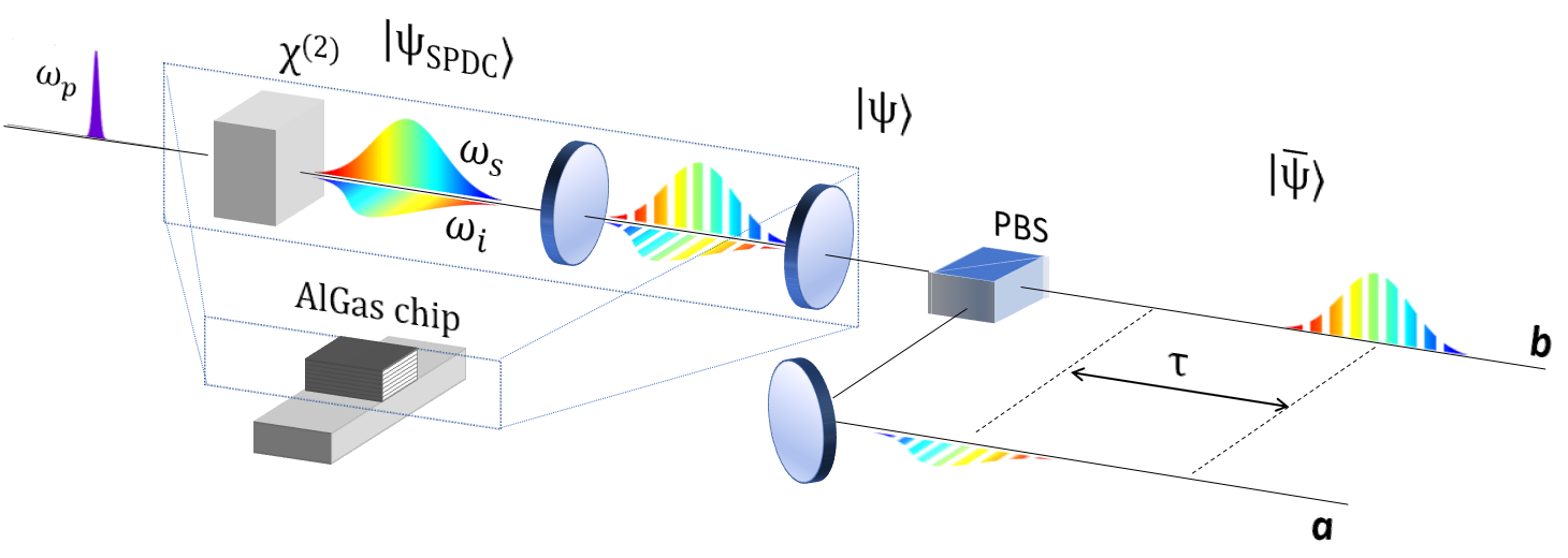
In Figure 1 we present the schematic of the experimental set up for the generation and symmetry manipulation of biphoton frequency combs. Photon pairs are generated by type II SPDC in a nonlinear medium: a pump photon at the frequency annihilates, generating two orthogonally polarized photons called signal (at frequency ) and idler (at frequency ). The resulting quantum state can be written as:
| (1) |
where is the joint spectral amplitude (JSA), i.e. the probability amplitude of having one of the photons at frequency with polarization and the other at frequency with polarization . For convenience we write the state using the basis and ; in this case, the JSA function takes the expression , where is the pump spectral profile and is the phase matching function depending on the material properties. For a pump frequency close to the degeneracy, is in good approximation a symmetric function in , centered in , whose bandwidth depends on the characteristics of the nonlinear medium Barbieri et al. (2017). An optical cavity discretizes the frequency space of the state (See Figure 1). At this stage the function associated to the cavity, which is the product of the signal and idler cavity transmission functions (), modulates the state JSA. The resulting state is a biphoton frequency comb, consisting in a sequence of phase-locked evenly-spaced peaks with a common phase originating from the pump Lu et al. (2003). Figure 2 (a) presents the numerical simulation of the corresponding joint spectral intensity (JSI=), which is the accessible function for experimental measurements. We show a zoom of the JSI around degeneracy, for a cavity consisting of a Fabry-Perot resonator of mirror reflectivity R=0.8, free spectral range and a pump laser of bandwidth . We observe that the JSI presents a periodic pattern with a fixed periodicity in both and directions. The number of peaks in the direction is determined by the width of the pump spectral profile, while the one in the direction is determined by the width of the function.
In the case of a monochromatic pump beam (linewidth ), the pump spectral profile can be approximated as = . The corresponding quantum state at the output of the cavity is:
| (2) |
By tuning of the pump frequency we have access to two classes of states, having different spectral pattern (See Figure 2(a)). For , with integer number, we generate resonant states, whose JSI maxima are disposed at even multiple of (See Figure 2(b)). In the approximation of a cavity with perfect reflectivity, the resonant state is:
| (3) |
For , we generate anti-resonant states, whose JSI maxima are disposed at odd multiples of (See Figure 2(c)). In the same approximation of a cavity with perfect reflectivity the anti-resonant state is:
| (4) |
(b-c) Corresponding simulation of the JSA (blue line: real part; red line: imaginary part), for (d, e) and (d, e).
The simulated JSA for intermediate values of the pump beam frequency is presented in the Supplementary Information (See Figure 1 Supplementary material).
In order to control the symmetry of the biphoton state, we introduce a third stage in the experimental setup, consisting of a polarizing beam splitter, separating deterministically the signal and idler photons into two different paths and , and a delay line on one of the two paths (see Figure 1). The introduced temporal delay modulates the JSA of the state with the periodic function , consisting of a symmetric real part and anti-symmetric imaginary part in the variable. For , corresponding to half of the cavity round trip time, the periodicity is the double of the one of state JSA. In this case, the JSA of the resonant state is in phase with the symmetric part of , resulting in the pattern of Figure 2(d). On the contrary the JSA of the anti-resonant state is in phase with the anti-symmetric part of resulting in the pattern of Figure 2(e). The resonant and anti-resonant states after the optical delay stage are:
| (5) | ||||
We note that the state is symmetric under particles exchange, while is anti-symmetric. Analog results occur for values that are odd multiples of the cavity half round-trip time (see Figure 2 in Supplementary Information).
We have thus demonstrated that the proposed experimental setup allows to generate biphoton frequency combs and to control their spectral symmetry by tuning the pump beam frequency.
In the following, we experimentally demonstrate this method using an AlGaAs chip. This platform combines a large second order optical susceptibility, a direct bandgap and a high electro-optic effect, making it attractive for the miniaturization and the integration of several quantum fonctionalities in a single chip Orieux et al. (2017); Günthner et al. (2015). The device consists of a Bragg reflection ridge waveguide optimized for efficient type II SPDC Yeh and Yariv (1976); Helmy (2006); Boitier et al. (2014) (See Supplementary Table 1 for details on the structure). The modes involved in the nonlinear process are a TE Bragg mode for the pump beam around 765 nm and TE00 and TM00 modes for the photon pairs in the C-telecom band. Note that, for this device, the group velocity mismatch between the two photons of each pair is so small that no off-chip compensation is required to preserve their indistinguishability Autebert et al. (2016); Günthner et al. (2015). The photon pairs are thus emitted in very good approximation with a joint spectral amplitude centered in and symmetric in the variable, enabling a direct implementation of our method. Moreover, the refractive index contrast between the semiconductor and the air, leads to a modal reflectivity at the waveguide facets of 0.27(0.24) for the TE(TM) polarized mode, creating a Fabry-Perot cavity surrounding the nonlinear medium. Our chip thus integrates the generation and the cavity stage of the experimental scheme represented in Figure 1, leading to an extremely simple and compact solution. Photon pairs are generated by pumping the device with a continuous wave laser having a linewidth of kHz, which is much smaller that the free spectral range of the cavity ( GHz).
Figure 3 reports the experimental measurement of the joint spectral intensity JSI= of the quantum state at the output of the AlGaAs chip, measured over a frequency range of 10 . The measurement is done by stimulated emission tomography Eckstein et al. (2014) for two values of the pump beam frequency separeted by . These results prove that the device emits a biphoton frequency comb and that the tuning of the pump frequency controls the transition from an resonant state to an anti-resonant one.
In order to quantify the level of mirror symmetry of the JSA function, we implement a HOM interferometer. Generated photons are separated with a fibered polarizing beam splitter, delayed by , their polarisation aligned with a half wave-plate, and they are recombined at a fibered 50/50 beam splitter. The two output ports are connected to single photon avalanche photodiodes having a detection efficiency of 25 and the coincidences counts are recorded with a time-to-digital converter. The obtained results for are reported in Figure 4: a dip having a width of 52 fs is observed. Similar results are obtained for . Its visibility defined as , where is the coincidences rate far from the interference region and the coincidence rate at the minimum of the dip, is 86. This value is limited by residual modal birefringence. The oscillating behavior observed around the dip is well-described by taking into account the chromatic dispersion of the sample, as shown by the result of the numerical simulation reported in Figure 4. From this simulation we can extract the emission bandwidth of the photon pairs, THz, corresponding to a signal and idler bandwidth of nm around 1530 nm (see details in Supplementary Information Figure 3-4). This result demonstrates that the device generates a broadband biphoton frequency comb, where the photons of each pair are in a coherent superposition of more than 500 peaks.
The control of the symmetry of the generated state is done by implementing the last stage of the experimental scheme presented in Figure 1, that is by adding a delay line on one of the output ports of the polarizing beam splitter and by choosing a temporal delay . This leads to the generation of the state for the resonant case and for the anti-resonant case.
In order to evaluate the symmetry of the JSA of these states, we rely on HOM interferometry: photon pairs described by a symmetric JSA are expected to bunch, whereas photon pairs described by an anti-symmetric wave function are expected to anti-bunch Fedrizzi et al. (2009). Figure 5 reports the experimental results of the HOM experiment: when we inject in the beam splitter the state a dip is observed, while when we inject in the beam splitter the state we obtain a peak. The observed visibility is , due to the combined effect of reflectivity Sagioro et al. (2004), birefringence and chromatic dispersion. Taking into account these effects, we predict that a spectral filter, centered at the frequency degeneracy and having a bandwidth of 25 nm, together with a reflection coating increasing the facets reflectivity to 0.5, would allow to reach a visibility of . We discuss the estimated visibility in the ideal case of zero birefringence (or compensated birefringence) and zero chromatic dispersion as a function of the reflectivity in the Supplementary material Figure 5.
We underline that the use of frequency anti-correlations and of a pump beam with a narrow spectral profile () are essential elements for the manipulation of the state symmetry; a broad pump would generate an uncorrelated state, consisting of a superposition of resonant and anti-resonant patterns, incompatible with this symmetry manipulation protocol.
In conclusion, we have proposed and demonstrated a method to generate and manipulate the symmetry of biphoton frequency combs based on the interplay between cavity effects and a delay line. The method can be adapted and applied to a large variety of systems, either bulk or integrated, thus increasing their flexibility and the richness of the generated states. In addition since it doesn’t rely on post selection, it can generate on demand anti-symmetric states. We have shown that AlGaAs Bragg reflector waveguides are a particularly convenient system to implement this method, thanks to the emission of photon pairs via type II SPDC (leading to a deterministic separation of the photon pairs), small birefringence of the generated modes (leading to a symmetric JSA with respect to frequency degeneracy and avoiding the requirement of off-chip compensation), and to the natural presence of a cavity (due to facets reflectivity). Further progress is possible in different ways: a full integration of the setup could be obtained by developing an on-chip polarizing beam splitter, as already demonstrated in Si-based devices Cai et al. (2017), and by controlling the relative delay between the orthogonally polarized photons through the electro-optic effect Wang et al. (2014). Moreover, the compliance AlGaAs chip with electrical injection at room temperature Boitier et al. (2014) paves the way towards the integration of the laser source within the chip, resulting in an extremely miniaturized and versatile system. These results open the way to new quantum protocols exploiting high-dimensional frequency states with controllable symmetry, such as the implementation of quantum logic gates through coherent manipulation of entangled frequency-bin qubits Jaramillo-Villegas et al. (2017), high-dimensional one-way quantum processing Reimer et al. (2018) or error correction in high-dimensional redundant states Fabre et al. (2019).
The authors gratefully acknowledge ANR (Agence Nationale de la Recherche) for the financial support of this work through Project SemiQuantRoom (Project No. ANR-14-CE26-0029) and through Labex SEAM (Science and Engineering for Advanced Materials and devices) project ANR 11 LABX 086, ANR 11 IDEX 05 02.The French RENATECH network and Université Sorbonne Paris Cité for PhD fellowship to G.M. are also warmly acknowledged.
References
- Flamini et al. (2018) F. Flamini, N. Spagnolo, and F. Sciarrino, Reports on Progress in Physics 82, 016001 (2018).
- Giovannetti et al. (2011) V. Giovannetti, S. Lloyd, and L. Maccone, Nature photonics 5, 222 (2011).
- O’Sullivan-Hale et al. (2005) M. N. O’Sullivan-Hale, I. Ali Khan, R. W. Boyd, and J. C. Howell, Phys. Rev. Lett. 94, 220501 (2005).
- Krenn et al. (2013) M. Krenn, R. Fickler, M. Huber, R. Lapkiewicz, W. Plick, S. Ramelow, and A. Zeilinger, Phys. Rev. A 87, 012326 (2013).
- McLaren et al. (2012) M. McLaren, M. Agnew, J. Leach, F. S. Roux, M. J. Padgett, R. W. Boyd, and A. Forbes, Opt. Express 20, 23589 (2012).
- Zhang et al. (2016) Y. Zhang, F. S. Roux, T. Konrad, M. Agnew, J. Leach, and A. Forbes, Science advances 2, e1501165 (2016).
- Thew et al. (2004) R. Thew, S. Tanzilli, A. Acin, H. Zbinden, and N. Gisin, (2004).
- Kues et al. (2017) M. Kues, C. Reimer, P. Roztocki, L. R. Cortés, S. Sciara, B. Wetzel, Y. Zhang, A. Cino, S. T. Chu, B. E. Little, D. J. Moss, L. Caspani, J. Azaña, and R. A. A. Morandotti, Nature 546, 622 (2017).
- Imany et al. (2018) P. Imany, J. A. Jaramillo-Villegas, O. D. Odele, K. Han, D. E. Leaird, J. M. Lukens, P. Lougovski, M. Qi, and A. M. Weiner, Opt. Express 26, 1825 (2018).
- Olislager et al. (2010) L. Olislager, J. Cussey, A. T. Nguyen, P. Emplit, S. Massar, J.-M. Merolla, and K. P. Huy, Phys. Rev. A 82, 013804 (2010).
- Kues et al. (2019) M. Kues, C. Reimer, J. M. Lukens, W. J. Munro, A. M. Weiner, D. J. Moss, and R. Morandotti, Nature Photonics 13, 170 (2019).
- Lu et al. (2003) Y. Lu, R. Campbell, and Z. Ou, Physical review letters 91, 163602 (2003).
- Xie et al. (2015) Z. Xie, T. Zhong, S. Shrestha, X. Xu, J. Liang, Y.-X. Gong, J. C. Bienfang, A. Restelli, J. H. Shapiro, F. N. C. Wong, and C. A. Wei Wong, Nature Photonics 9, 536 (2015).
- Jin et al. (2016) R.-B. Jin, R. Shimizu, M. Fujiwara, M. Takeoka, R. Wakabayashi, T. Yamashita, S. Miki, H. Terai, T. Gerrits, and M. Sasaki, Quantum Science and Technology 1, 015004 (2016).
- Jeronimo-Moreno et al. (2010) Y. Jeronimo-Moreno, S. Rodriguez-Benavides, and A. B. U’Ren, Laser Physics 20, 1221 (2010).
- Goyal et al. (2014) S. K. Goyal, P. E. Boukama-Dzoussi, S. Ghosh, F. S. Roux, and T. Konrad, Scientific Reports 4, 4543 EP (2014), article.
- Jex et al. (2003) I. Jex, G. Alber, S. Barnett, and A. Delgado, Fortschritte der Physik 51, 172 (2003).
- Sagioro et al. (2004) M. A. Sagioro, C. Olindo, C. H. Monken, and S. Pádua, Phys. Rev. A 69, 053817 (2004).
- Olindo et al. (2006) C. Olindo, M. Sagioro, C. Monken, S. Pádua, and A. Delgado, Physical Review A 73, 043806 (2006).
- Boitier et al. (2014) F. Boitier, A. Orieux, C. Autebert, A. Lemaître, E. Galopin, C. Manquest, C. Sirtori, I. Favero, G. Leo, and S. Ducci, Phys. Rev. Lett. 112, 183901 (2014).
- Barbieri et al. (2017) M. Barbieri, E. Roccia, L. Mancino, M. Sbroscia, I. Gianani, and F. Sciarrino, Scientific reports 7, 7247 (2017).
- Orieux et al. (2017) A. Orieux, M. A. M. Versteegh, K. D. Jöns, and S. Ducci, Reports on Progress in Physics 80, 076001 (2017).
- Günthner et al. (2015) T. Günthner, B. Pressl, K. Laiho, J. Geßler, S. Höfling, M. Kamp, C. Schneider, and G. Weihs, Journal of Optics 17, 125201 (2015).
- Yeh and Yariv (1976) P. Yeh and A. Yariv, Optics Communications 19, 427 (1976).
- Helmy (2006) A. Helmy, Optics express 14, 1243 (2006).
- Autebert et al. (2016) C. Autebert, N. Bruno, A. Martin, A. Lemaitre, C. G. Carbonell, I. Favero, G. Leo, H. Zbinden, and S. Ducci, Optica 3, 143 (2016).
- Eckstein et al. (2014) A. Eckstein, G. Boucher, A. Lemaître, P. Filloux, I. Favero, G. Leo, J. E. Sipe, M. Liscidini, and S. Ducci, Laser & Photonics Reviews 8, L76 (2014).
- Fedrizzi et al. (2009) A. Fedrizzi, T. Herbst, M. Aspelmeyer, M. Barbieri, T. Jennewein, and A. Zeilinger, New Journal of Physics 11, 103052 (2009).
- Cai et al. (2017) H. Cai, C. M. Long, C. T. DeRose, N. Boynton, J. Urayama, R. Camacho, A. Pomerene, A. L. Starbuck, D. C. Trotter, P. S. Davids, et al., Optics Express 25, 12282 (2017).
- Wang et al. (2014) J. Wang, A. Santamato, P. Jiang, D. Bonneau, E. Engin, J. W. Silverstone, M. Lermer, J. Beetz, M. Kamp, S. Höfling, et al., Optics Communications 327, 49 (2014).
- Jaramillo-Villegas et al. (2017) J. A. Jaramillo-Villegas, P. Imany, O. D. Odele, D. E. Leaird, Z.-Y. Ou, M. Qi, and A. M. Weiner, Optica 4, 655 (2017).
- Reimer et al. (2018) C. Reimer, S. Sciara, P. Roztocki, M. Islam, L. R. Cortés, Y. Zhang, B. Fischer, S. Loranger, R. Kashyap, A. Cino, et al., Nature Physics , 1 (2018).
- Fabre et al. (2019) N. Fabre, G. Maltese, F. Appas, S. Felicetti, A. Ketterer, A. Keller, T. Coudreau, F. Baboux, M. Amanti, S. Ducci, and P. Milman, In preparation (2019).