KEK Preprint 2019-1
March 2019
H
A 15-MW Proton Driver for
Neutrino Oscillation Experiments
R. Belusevic
IPNS, High Energy Accelerator Research Organization (KEK)
1-1 Oho, Tsukuba, Ibaraki 305-0801, Japan
r.belusevic@gmail.com
References
Abstract : To maximize the physics potential of future neutrino oscillation experiments, it is proposed to build a 15-MW ‘proton driver’ consisitng solely of a 3-GeV proton injector linac (PI) and a 17-GeV superconducting ILC-type linac (SCL). The proposed facility would provide proton beams with intensities more than an order of magnitude higher than those at the existing proton synchrotron complexes. Multi-MW proton beams could also be used to produce high-intensity antiproton, ‘cold’ neutron, kaon, pion and muon beams for a diverse program of experiments in particle and nuclear physics.
1 Introduction
Many important discoveries in particle physics (such as flavor mixing in quarks and in neutrinos) have been made using proton beams with relatively low energies but high intensities. With this in mind, at a number of laboratories worldwide interest has been expressed to build facilities that would provide high-intensity proton beams for various fixed-target experiments [1, 2].
Experiments with high-intensity neutrino beams, for instance, are designed primarily to explore the mass spectrum of the neutrinos and their properties under the CP symmetry. If there is experimental evidence for CP violation in neutrino oscillations, it could be used to explain the observed asymmetry between matter and antimatter in the universe — a basic precondition for our existence.
Studies of CP violation in the neutrino sector require multi-MW proton beams. Such beams cannot be provided by any facility that includes proton synchrotrons, because the beam power in a circular accelerator is limited by the space charge effects that produce beam instabilities. To increase maximally the beam power of a ‘proton driver’, it is proposed to build a 15-MW accelerator consisting solely of a 3-GeV injector linac (PI) and a 17-GeV superconducting ILC-type linac (SCL) A similar facility was originally proposed in [3].
At a pulsed linear accelerator, the beam power increases linearly with the beam energy:
| (1) |
is the beam energy, is the average current per pulse, is the beam pulse length, and is the pulse repetition rate. Assuming MV, mA, ms and , expression (1) yields MW. This is over an order of magnitude higher than the beam power at any existing proton synchrotron complex.
2 A Two-Linac Proton Driver
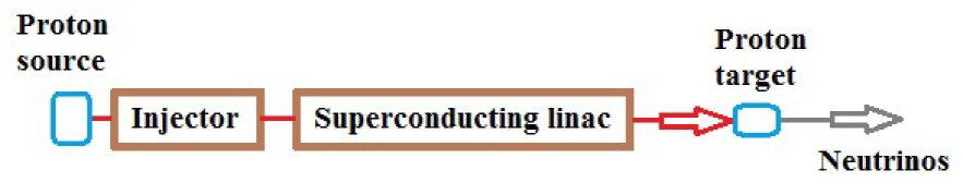
The layout of the proposed ‘proton driver’ is shown in Fig. 1. A 3-GeV proton linac (PI) serves as an injector to an ILC-type superconducting linac (SCL). The main SCL beam parameters are given in Table 1. Protons accelerated by the SCL to 20 GeV would be used primarily to create beams for neutrino oscillation experiments.
The typical properties of a 1.3-GHz superconducting ILC-type cavity are presented, e.g., in [4]. Each ILC-type cryomodule for the proposed SCL would contain eight niobium 9-cell cavities and a focusing quadrupole magnet at its centre. The inactive regions between cavities or cryomodules (the ‘packing fraction’) are responsible for a reduction in the average accelerating gradient of the linac.
The average usable accelerating gradient in ILC-type cavities is MV/m [5]. Taking into account an estimated linac ‘packing fraction’ of about 70%, the effective accelerating gradient of the SCL is E MV/m. Hence, the total length of a 17-GeV linac is 850 m.
| Beam energy | 17 GeV |
|---|---|
| Effective accelerating gradient | 20 MV/m |
| Repetition rate | 20 Hz |
| Protons per pulse | |
| Beam pulse length | 1.2 ms |
| Average current per pulse | 32 mA |
| Duty factor | 2.4 % |
| RF frequency | 1.3 GHz |
| Klystron average power | 150 KW |
| Klystron peak power | 5 MW |
| Klystron pulse length | 1.5 ms |
| Peak power per coupler | 312 kW |
Since the length of an ILC 9-cell cavity is 1m, a linac with energy GeV would require cavities. The average input rf power per cavity is therefore kW, and the corresponding peak power kW. If two rf couplers per cavity are used, the peak rf power per coupler is reduced to 312 kW. For E MV/m, ohmic losses in an ILC 9-cell cavity amount to W (plus static loss) in the pulsed mode with a duty factor .
For a pulsed ILC-type superconducting linac, one of the currently available rf sources is the Toshiba E3736 Multi-Beam Klystron [6]. This source has the following properties: rf frequency – 1.3 GHz; peak rf power – 10 MW; average power – 150 kW; efficiency – 65%; pulse length – 1.5 ms; repetition rate – 10 Hz.
To increase the beam power of the SCL, the pulse repetition rate could be increased to 20 Hz (see Eq. (1)). The peak power of each klystron would then have to be reduced to 5 MW in order to maintain its average power at 150 kW for the klystron pulse length ms (see Table 1). In this case a suitable 20 Hz pulse modulator would be required.
2.1 Proton Injector (PI)
A typical proton linear accelerator consists of three main sections: (1) Front end, which includes a proton source and a radiofrequency quadrupole accelerator; (2) Medium-velocity linac, where the proton beam energy is increased to a few hundred MeV; (3) High-velocity linac, which accelerates protons to energies above 1 GeV.
A detailed beam dynamics study of a high-power proton linac is needed in order to avoid halo formation, a major source of beam loss. Another crucial issue is the preservation of beam emittance. Either of the following two accelerator designs could serve as a prototype of the 3-GeV injector linac in Fig. 1:
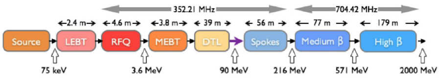
The European Spallation Source (ESS) linac, a 2-GeV proton linear accelerator currently under construction in Lund, Sweden (see Fig. 2). The transverse beam size along the linac varies between 1 mm and 4 mm, while the bunch length decreases from 1.2 cm to 3 mm towards the end of the linac. The total length of the accelerator is about 360 m.
| Beam kinetic energy | 8 GeV |
|---|---|
| Beam current averaged over the pulse | 25 mA |
| Pulse repetition rate | 10 Hz |
| Pulse length | 1 ms |
| Beam pulsed power | 200 MW |
| Beam average power | 2 MW |
| Wall-plug power (estimate) | 12.5 MW |
| Total length | 678 m |
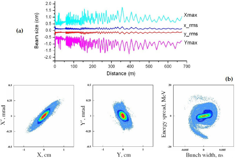
An 8-GeV linac for a ‘proton driver’ at Fermilab [8]. The linac consits of a front-end section that accelerates protons to energies of about 420 MeV, and a high-energy section operating at rf frequencies of 325 MHz and 1300 MHz respectively. A room temperature radio frequency quadrupole (RFQ) and short H-type resonators are proposed for the initial acceleration of proton beams to energies of MeV. In the energy range 10–420 MeV the acceleration is provided by superconducting spoke resonators, and in the high-energy section by ILC-type elliptical cell cavities.
The basic parameters of the proposed 8-GeV linac are listed in Table 2. The beam physics and the lattice design of the linac are described in [8]. Some of the results of end-to-end beam dynamics simulations are presented in Fig. 3 (Section 7 in [8]). The block diagram of the linac is shown in Subsection 3.3 of [8].
2.2 Proton Target and Magnetic Horn for Neutrino Beams
When designing a multi-MW neutrino beam facility, one of the main challenges is to build a proton target that could withstand the strong pressure waves created by short beam pulses, dissipate large amounts of deposited energy, and survive long-term effects of radiation damage. Computer simulations of the pion production and energy deposition in different targets (solid tungsten bars; jets of liquid mercury, liquid gallium and tungsten powder) are described in [9].
A 4 MW target station comprising a liquid mercury jet inside a 20 T solenoidal magnetic field was tested in 2007 at CERN [10]. An alternative design is a rotating, gas-cooled tungsten target that would require the least amount of development effort, and would have good thermal and mechanical properties [7]. To reduce the beam power delivered to a target, a 15-MW proton beam could be separated by a series of magnets into three beam lines. Each of the 5-MW beams would be guided to an assembly consisting of three targets and the same number of magnetic horns, devices that focus the charged particles produced in the proton target (see, e.g., [11]).
For proton beam pulses lasting 1 ms, a DC horn has been designed at KEK by Yukihide Kamiya [12]. The toroidal magnetic field of the horn, generated by hollow aluminium conductors that contain cooling water, has the same strength at all radii: B 0.2 T. The outer radius of the magnet, , is determined by
| (2) |
where is the initial angle of a charged pion with respect to the proton beam direction, is the distance from the target to the horn, m is the length of the magnet, and is the pion momentum. The total power generated in the conductors is about 10 MW.
3 Significance of Neutrino Oscillations
Observation of the quantum-mechanical phenomenon of neutrino oscillations implies that at least one kind of neutrino has non-zero mass. The actual mechanism of neutrino mass generation is still not known. In the Standard Model of particle physics, fermions acquire mass through interactions with the Higgs field, an entity that permeates the universe. These interactions involve both left- and right-handed versions of each fermion. However, only left-handed neutrinos (and righ-handed antineutrinos) have been observed so far. The discovery of neutrino oscillations in 1998 represents, therefore, compelling experimental evidence for the incompleteness of the Standard Model as a description of nature.
The universe contains about a billion neutrinos for every quark or electron. Relic neutrinos from the early universe are almost as abundant as cosmic microwave background photons (about 330 neutrinos and antineutrinos of all species per cm3, compared to about 410 photons per cm3). Cosmological data suggest that the combined mass of all three neutrino species (‘flavors’) is at least a million times smaller than that of the next-lightest particle, the electron.
The phenomenon of neutrino oscillations implies not only the existence of neutrino mass, but also of neutrino mixing: the neutrinos of definite flavor are not particles of definite mass (mass eigenstates), but coherent quantum-mechanical superpositions of such states. Converesely, each neutrino of definite mass is a superposition of neutrinos of definite flavor.
A neutrino state with a well-defined flavor, , can be expressed in terms of mass eigenstates as follows:
| (3) |
Here is a complex unitary matrix, called the mixing matrix. For neutrino oscillations in vacuo, one can use this expression to derive the probability that a different flavor eigenstate will be observed at time :
| (4) |
In Eq. (4),
| (5) |
where are the mass-squared differences, E is the common energy of all components, and is the distance travelled by a flavor eigenstate to the detector where is observed. Here it is assumed that , produced at a neutrino source, propagates as a superposition of mass eigenstates .
The neutrino oscillation rate depends, in part, on () the difference between neutrino masses and () the three parameters in the mixing matrix known as the mixing angles. As one can infer from Eq. (4), if all . Thus, observation of neutrino oscillations implies that at least one kind of neutrino has non-zero mass, as already stated.
The complex phase factors in the mixing matrix are associated with the violation of CP symmetry. In neutrino oscillations, CP violation is observed only if all the mixing angles and all the mass differences are nonvanishing [13]. If there is no CP violation, which means that , the last term in Eq. (4) vanishes.
As mentioned in the Introduction, experimental evidence for CP violation in neutrino oscillations could be used to explain the observed asymmetry between matter and antimatter in the universe. Since this asymmetry is a basic precondition for our existence, search for CP violation in the lepton sector is the holy grail of neutrino physics.
4 Acknowledgements
For valuable comments and suggestions concerning various aspects of this work I am grateful to Y. Kamiya and K. Oide. I wish to express my special gratitude to Kaoru Yokoya for his help and encouragement.
This paper is based on the idea originally presented in the KEK Preprint 2014-35 (2014), which was subsequently published as an arXiv e-print (arXiv:1411.4874) and [3].
References
- [1] R. Garoby et al., Proton drivers for neutrino beams and other high intensity applications, Journal Phys. Conf. Series 408, 012016 (2013).
- [2] E. Baussan et al., A very intense neutrino super beam experiment for leptonic CP violation discovery based on the European spallation source linac, Nucl. Phys. B 885, 127–149 (2014).
- [3] R. Belusevic, A multi-MW proton/electron facility at KEK, J. Appl. Math. Phys. 5, 1222–1242 (2017).
- [4] A. Yamamoto, Superconducting RF cavity development for the International Linear Collider, IEEE Trans. Appl. Supercond. Vol. 19, No. 3, pp 1387–1393 (2009); T. Saeki et al., Study on fabrication of superconducting RF 9-cell cavity for ILC at KEK, Proc. IPAC 2013, Shanghai, China, pp 3132–3134 (2013).
- [5] D. Reschke, Infrastructure, methods and test results for the testing of 800 series cavities for the European XFEL, Proc. SRF 2013, Paris, France, pp 812–815 (2013).
- [6] A. Yano et al., The Toshiba E3736 Multi-Beam Klystron, Proc. LINAC 2004, Lübeck, Germany, pp 706–708 (2004).
- [7] H. Danared, M. Lindroos and C. Theroine, ESS: neutron beams at the high-intensity frontier, CERN Courier, June 2014, pp 21–24.
- [8] P. N. Ostroumov, Physics design of the 8 GeV H-minus linac, New J. Phys. 8 (2006) 281.
- [9] J. Back et al., Particle production and energy deposition studies for the neutrino factory target station, Phys. Rev. Spec. Topics — Accelerators and Beams 16, 021001 (2013).
- [10] K. T. McDonald et al., The MERIT high-power target experiment at the CERN PS, in Proc. First International Particle Accelerator Conf., Kyoto, Japan, pp 3527–3529 (2010).
- [11] E. Baussan et al., Target, magnetic horn and safety studies for the CERN to Frejus Super Beam, Journal of Phys. Conf. Series 408, 012061 (2013).
- [12] Y. Kamiya, DC neutrino horn; the manuscript (in Japanese) has not been published.
- [13] G. Bellini et al., Neutrino Oscillations, Adv. High. En. Phys., Volume 2014, Article ID 191960 (2014).