High sensitivity VLBI with SKA
Abstract:
The Square Kilometre Array (SKA), with the aim of achieving a collecting area of one square kilometre, will be the world’s largest radio telescope. A scientific collaboration between 12 countries (with more to join), it will consist of one Observatory with 2 telescopes located in South Africa and Australia. The telescope deployment is planned in two phases, but even in its first stage (SKA1) it will already enable transformational science in a broad range of scientific objectives. The inclusion of SKA1 in the Global VLBI networks (SKA-VLBI) will provide access to very high angular resolution to SKA science programmes in anticipation of the science to be realized with the full telescope deployment (SKA2). This contribution provides an overview of the SKA Observatory VLBI capability, the key operational concepts and outlines the need to update the science use cases.
1 The Square Kilometre Array
The Square Kilometre Array (SKA) will be the world’s largest radio telescope ever constructed. It will be a multi-purpose radio observatory, designed to cover the frequency range from 50 MHz up to 20 GHz, that will play a major role in answering key questions in modern astrophysics and cosmology. The SKA Observatory will include two very different radio telescopes in terms of the receiving elements used. The LOW telescope will be located at the Murchison Radio Astronomy Observatory in Australia and the MID telescope in the Karoo region in South Africa. The headquarters will be located at the Jodrell Bank Observatory in the United Kingdom.
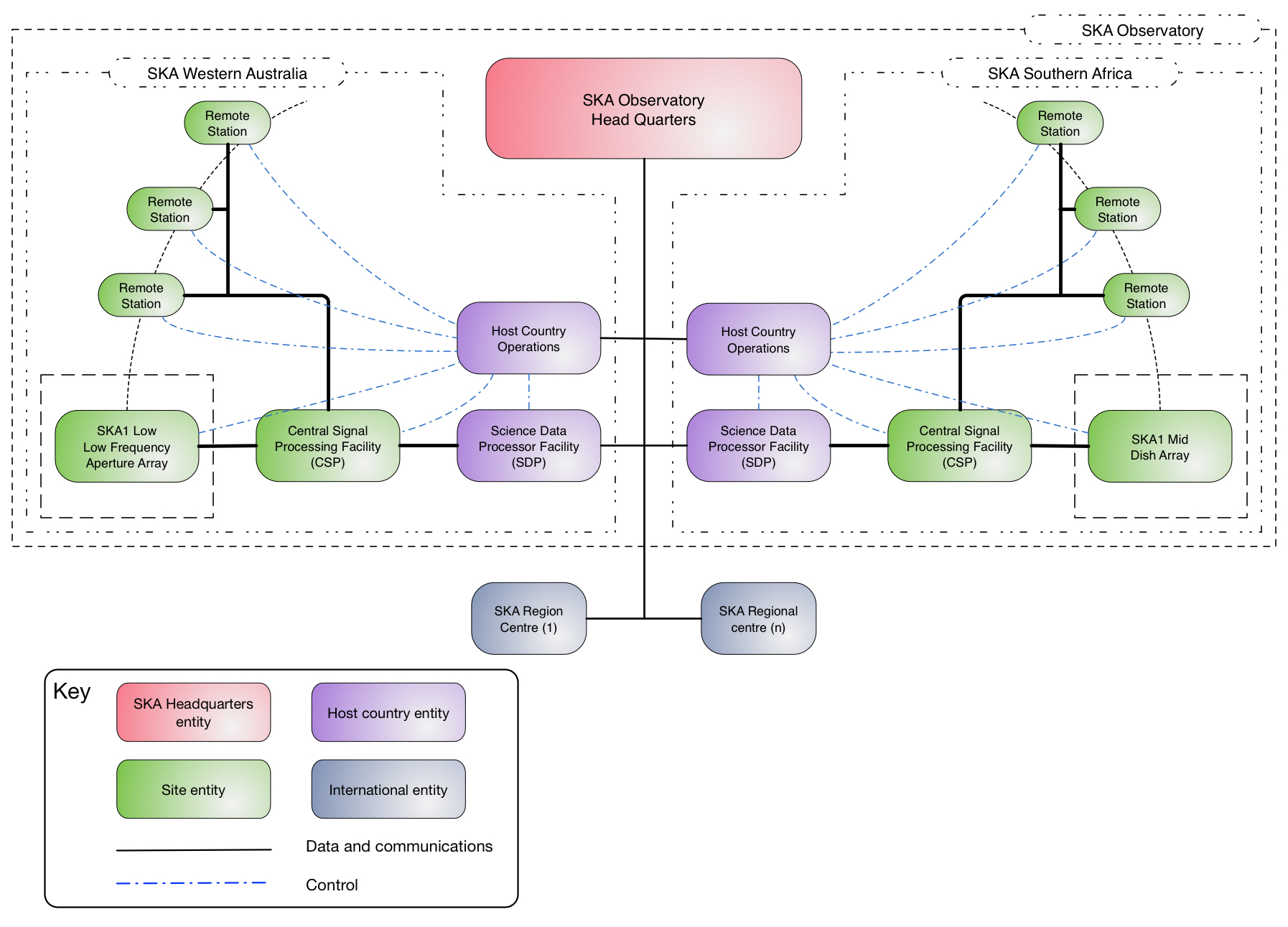
Due to the magnitude of the project it is planned to be deployed in two phases. The design of the first phase, SKA1, is supported by a broad international collaboration organised into different Consortia, each responsible for the design of a distinctive component or element of the telescopes, e.g. dishes, correlator, signal and data transport, etc. (see Fig. 1). At the time of writing, this design is being finalised with the Critical Design Reviews (CDRs) of the different elements, and nearing completion. Once the elements’ designs have been evaluated and closed-out, the Consortia dissolve and a Bridging Phase starts with support from the former participant institutions. The Bridging Phase prepares for a System Level Critical Design Review to assess the design of the full SKA1 Observatory, and leads towards construction.
2 Implementing VLBI at the SKA1
Comparing to existing radio interferometers, the SKA telescopes will access a wide range of angular resolutions. In its initial phase, SKA1 will greatly surpass the capability of currently operational, connected interferometers in terms of sensitivity, survey speed and sub-arcsecond angular resolution. But in terms of the latter, there are science cases that would benefit from resolutions that are not achievable with connected-element interferometers. Nowadays the highest angular resolutions are achieved by Global VLBI observations, which use coordinated networks of radio telescopes located around the globe and in space, to synthesise an equivalent Earth size instrument or even larger. Inclusion of SKA1 in the Global VLBI networks (SKA-VLBI) will provide multi-beam capability with Jy sensitivity in N-S baselines with access to the Southern Hemisphere and simultaneous images of the sky at a broad range of angular resolutions, down to sub-milliarcseconds for the higher observing frequencies of the SKA ([1], and references therein). The boost in sensitivity will allow efficient VLBI surveys of the sub-mJy source population and access to the Jy regime for individual sources, with improved fidelity due to the SKA superior amplitude and polarization calibration. The multi-beam capability will enable high precision astrometry and enhanced phase referencing techniques, transient localisation, etc.
The Horizon 2020 JUMPING JIVE project recognised the scientific relevance of the SKA-VLBI. It has a devoted work package, “VLBI with SKA”, to focus on the definition of a SKA-VLBI Operational Model, define VLBI interfaces and requirements for the SKA, and to help the community develop Science Use Cases for SKA-VLBI and strategies for possible future SKA-VLBI Key Science Projects (KSPs) [2]. It will provide four main deliverables, scheduled in a period of 42 months. This contribution summarises the outcomes of the first deliverable “Details on VLBI Interfaces to SKA Consortia”. This consists of a description of the VLBI element that will provide the buffering and streaming capability to send SKA VLBI data to an external VLBI correlator, as well as all necessary interfaces for scheduling and conducting VLBI observations with the SKA.
3 SKA-VLBI Capability
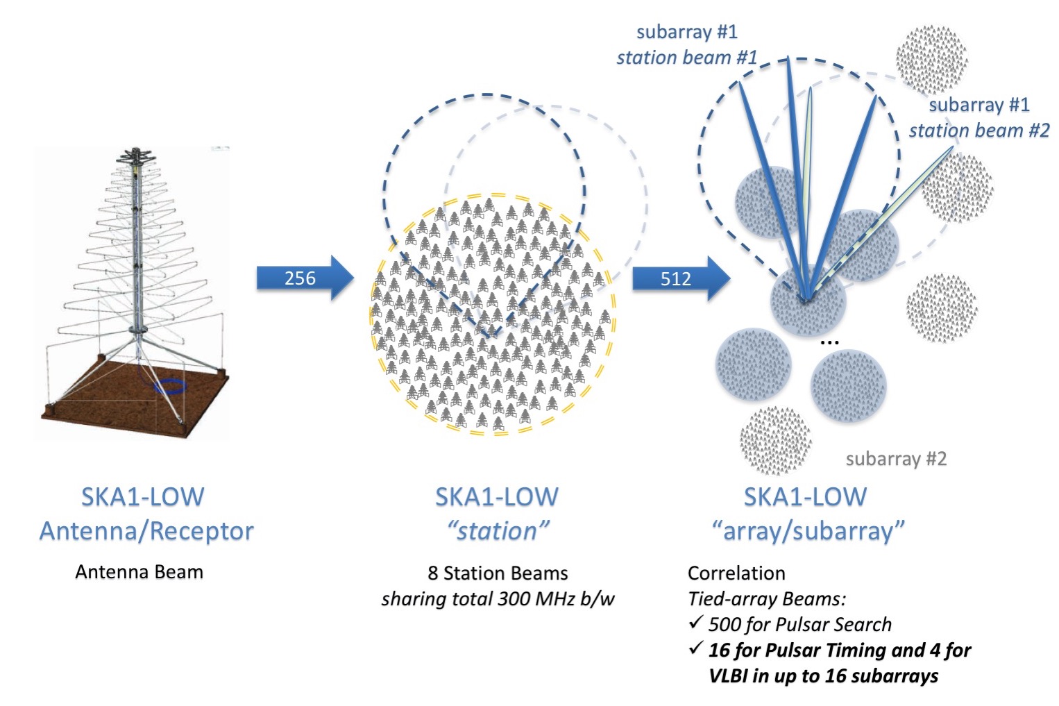
VLBI will be an observing mode of the SKA Observatory with the aim of including the participation of the SKA1 LOW and MID telescopes in Global VLBI observations. In this mode, SKA1 provides multiple sensitive VLBI tied-array beams for inclusion in VLBI observations. Each SKA1 VLBI beam acts as an individual element in the VLBI network, equivalent to an individual single beam radio telescope participating in the observation. Tied-array beams are produced by a beamformer in the SKA correlator. Each tied-array beam is formed within a subset (or subarray) of LOW stations or MID dishes by coherently combining the signals from the receptors, such that the combined gain is directed at a specified point on the sky. At least 4 dual-polarisation VLBI beams are formed from one or more subarrays, compatible with the standard VLBI observing mode. The SKA Observatory Data Products for this mode are: VLBI voltage beams formatted into VDIF (VLBI standard for data interchange format) packets to be correlated at an External Correlator, associated metadata, and image cubes produced by the Science Data Processor (SDP) from the same subarray from which the VLBI beams were formed. These simultaneous images will be used to calibrate the VLBI data, as well as to complement the science data return by providing images of the sky with different bandwidths and angular and spectral resolutions.
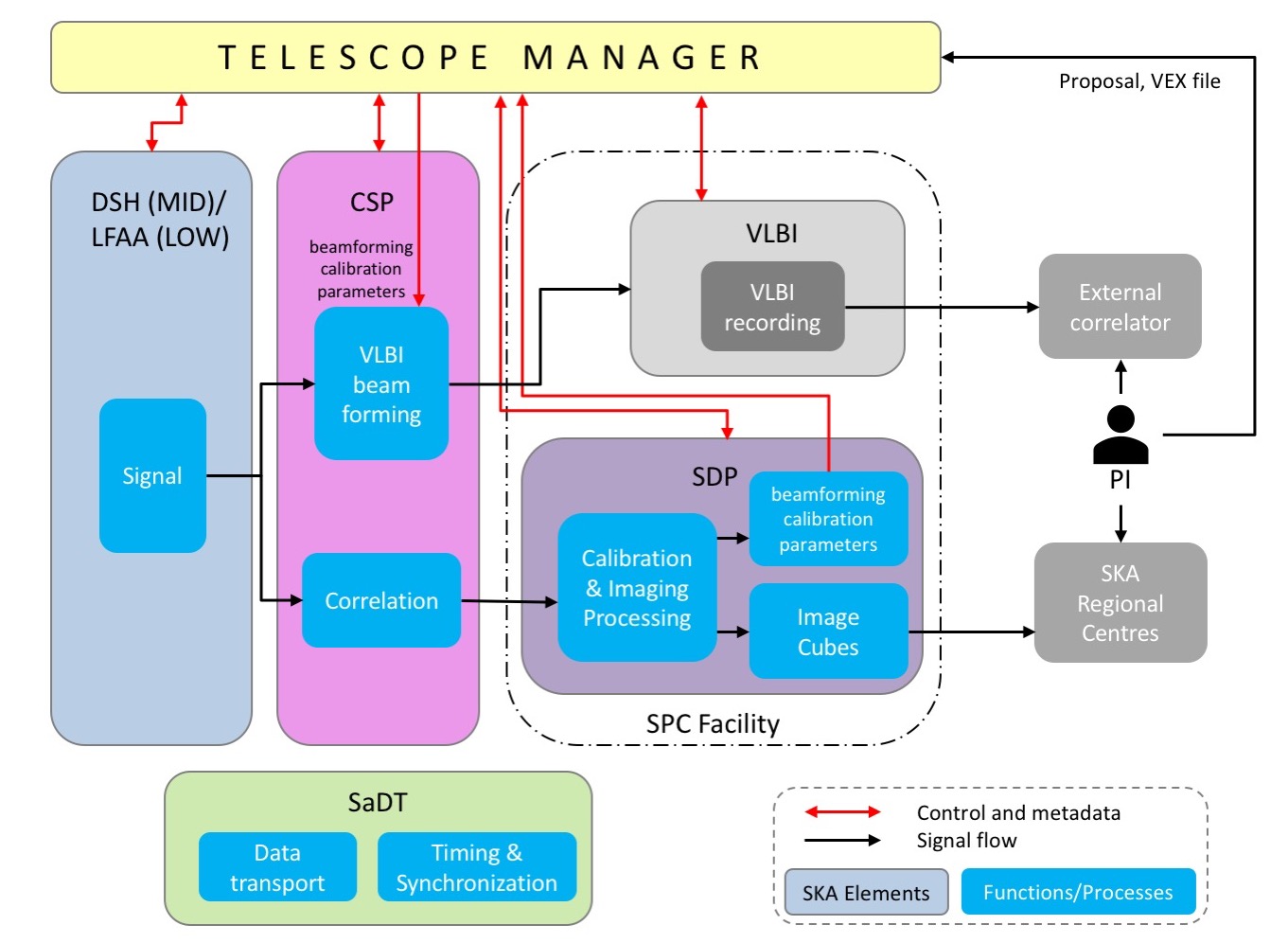
The key operational concepts of the SKA Observatory [3] that define how the VLBI operations will be performed are (i) the ability to configure and simultaneously operate independent subarrays, (ii) the simultaneity of Imaging and VLBI observing modes in the same subarray for calibration and commensal science and (iii) the independent multi-beam capability for each subarray. The VLBI Operational workflow will be as follows (Fig. 2):
-
•
Approved observing proposals become Observatory Projects. The PI will provide all necessary information for the observation design, in particular the VEX file (version 2.0) that describes all the details needed to perform the VLBI observation and to correlate it. With this information the observation is planned and scheduled, and a Scheduling Block (SB) is generated for observation execution. These functions are performed by the Telescope Manager (TM) element.
-
•
Digitised signals from the receivers (LOW log-periodic antennas, or MID dishes) are fed into the Correlator BeamFormers (CBF) of the Central Signal Processor (CSP), located at each SKA1 telescope site. Apart from complex correlation, the correlators form tied-array beams for VLBI, Pulsar Timing and Pulsar Search. The VLBI beams are corrected for polarization impurity, channelized in real representation, and formatted into VDIF packets. Channels that are adversely affected by RFI are either excised or flagged accordingly.
-
•
VLBI VDIF packets are sent to the VLBI Terminal located at the Science Processing Centre (SPC) for either real-time streaming to the External correlator (e-VLBI mode) or for recording (buffering) and streaming after the observation has completed. The e-VLBI mode has several advantages over the recorded mode, such as real-time fringe verification and troubleshooting, fast scientific turnaround, observing configuration adaptability, etc. The VLBI Terminal has access to the Observatory metadata via subscription to the TM element to generate an observing log in support for the external correlation and imaging post-processing calibration.
-
•
Simultaneously, the correlator visibilities are received by the Science Data Processor (SDP) and processed by the real-time calibration pipeline. This pipeline calculates the beamforming calibration parameters (delay models, complex gains, polarisation corrections, etc.) that are then sent to the CBF via the metadata flow managed by TM. The real-time calibration must be determined and applied to maximise the coherent tied-array beam gain as well as its polarisation purity while counteracting possible ionospheric position jitter. Correlator visibilities are also processed by SDP to produce image cubes that are sent to the SKA Regional Centres (SRCs) for further processing and analysis.
-
•
In parallel, the Signal and Data Transport (SaDT) element is responsible for the science data and non-science data communications links, that route VLBI data to the VLBI Terminal from the correlators and connect with TM for monitor and control tasks. The SaDT element is also responsible for the realisation of the SKA timescale based on the use of hydrogen masers which provide a phase-coherent reference signal with the stability required by VLBI.
-
•
The PI accesses the data products from the external correlator (VLBI visibilities, pipeline products including VLBI images and metadata, etc.) and from the SRCs (images in support of VLBI calibration and, if justified in the VLBI proposal, full resolution imaging data products from the same subarray and/or the whole array).
3.1 VLBI with the SKA1-MID
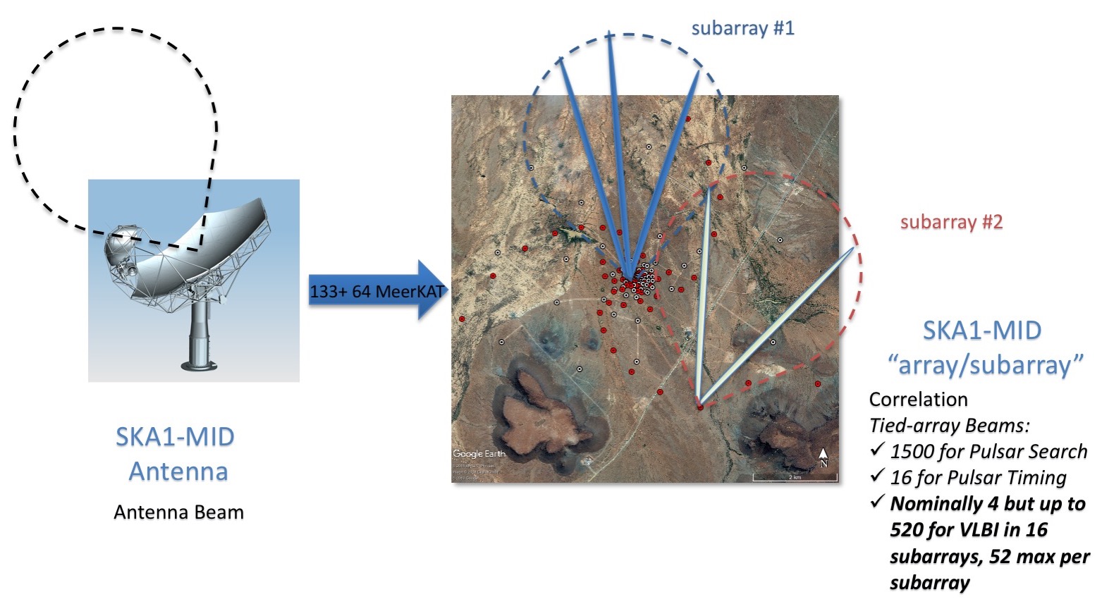
The SKA1-MID correlator and beamformer design presents a FX-type FPGA based correlator with a very flexible architecture that efficiently manages its processing resources [4]. It is able to simultaneously process up to 16 independent subarrays, as well as all observing modes simultaneously within each subarray. To do so requires a bandwidth sacrifice, especially for Band 5 (4.6-15.3 GHz). The architecture allows input from 200 antennas separated by several 1000s km and can be easily upgraded to support 20% more antennas. The input signal from the different observing bands is divided into 200 MHz frequency chunks, called Frequency Slices, with each slice processed by a Frequency Slice Processor (FSP) - a set of FPGAs configured to perform correlation or the different types of tied-array beamforming. The MID correlator is required to form, in different directions on the sky, 1500 beams for Pulsar Search (PSS), 16 beams for Pulsar Timing (PST) and 4 beams for VLBI. The beams can be produced from the same subarray or distributed amongst different subarrays.
The VLBI beams can be formed using different subarray sizes, up to the full telescope array, with the caveat that longer baselines will suffer from coherence losses and the beams will provide limited FoV. The VLBI capability of MID surpasses that in the System Level 1 requirements [5], by providing a total of 520 VLBI beams of 200 MHz effective bandwidth in dual polarisation from a total of 16 subarrays. Each subarray can produce a maximum of 52 beams of 200 MHz effective bandwidth, or a lesser number of beams but with larger bandwidths, e.g. 4 beams of 2.5 GHz bandwidth in dual polarisation (Fig. 3).
At the 200 MHz level the RFI contamination is flagged or excised if present and polarisation leakage is corrected. Each 200 MHz frequency slice is channelised in up to 4 dual polarisation beam channels (i.e. subbands in VLBI jargon), with a tunable centre frequency, and bandwidths ranging from 1 to 128 MHz and up to the full 200 MHz bandwidth. Digitisation uses 2 to 16 bits per sample with Nyquist sampling. Beam channels are formatted in VDIF packets using real representation, that are streamed to the VLBI terminal. Power levels in the beam channels and beamforming weights are provided as part of the metadata. Together with VLBI beams, the MID correlator provides visibility data at reduced spectral resolution compared to normal imaging visibilities, to provide calibration solutions to establish beam coherence and for imaging products in support of VLBI calibration.
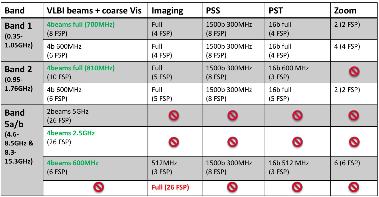
The MID correlator initial deployment will provide enough processing resources to be able to process the full 5 GHz instantaneous Band 5 bandwidth for just one processing mode at a time. For example for full bandwidth imaging in Band 5, all 26 available FSPs are required. Full simultaneity (commensality) of the different observing modes is achieved in all bands for each subarray for moderate observing bandwidths (Fig. 4).
3.2 VLBI with the SKA1-LOW
The SKA1-LOW correlator and beamformer design also presents an FX-type FPGA based correlator. The correlator is not limited by processing resources as the bandwidth to be processed is much narrower (300 MHz bandwidth between 50-350 MHz) [4]. The resources required are available to provide all different processing modes, Imaging and tied-array beamforming, for each subarray simultaneously, for up to 16 independent subarrays.
The LOW correlator is required to form, in independent directions, 500 beams for the Pulsar Search (PSS), 16 beams for Pulsar Timing (PST) and 4 beams for VLBI. The beams can be produced from the same subarray or distributed amongst different subarrays (Fig. 5). The maximum subarray size for tied-array beamforming is up to 20 km in diameter. The beamforming process for PST and VLBI beams is exactly the same, sharing the resources for up to 16 beams. In principle VLBI requires the use of 4 PST beams but it could process more if they are not used by PST.
The VLBI beams have a maximum bandwidth of 256 MHz per polarisation. Before beamforming, at the LFAA fine channel level, RFI contamination is flagged or excised and the polarisation leakage is corrected. Each VLBI beam is channelised in up to 4 dual polarisation beam channels contiguous in frequency, with a tunable centre frequency and bandwidths ranging from 1 to 64 MHz. Digitisation uses 2 to 8 bits per sample and up to 2x Nyquist oversampling. Beam channels are formatted in VDIF packets using real representation, that are streamed to the VLBI terminal. Power levels in the beam channels and beamforming weights are provided as part of the metadata.
3.3 VLBI element of the SKA1
The VLBI element falls under the responsibility of an international VLBI Consortium. It will be composed of a VLBI terminal with VDIF recorders, monitor and control software, and the necessary scripts to carry out the observations. To allow easy access for the VLBI Consortium to the VLBI terminal, and to not impose additional burden to the very restricted RFI control at the telescopes sites, the VLBI terminal will be installed at the Science Processing Centres (SPC), located in Perth and Cape Town for SKA1-LOW and SKA1-MID, respectively.
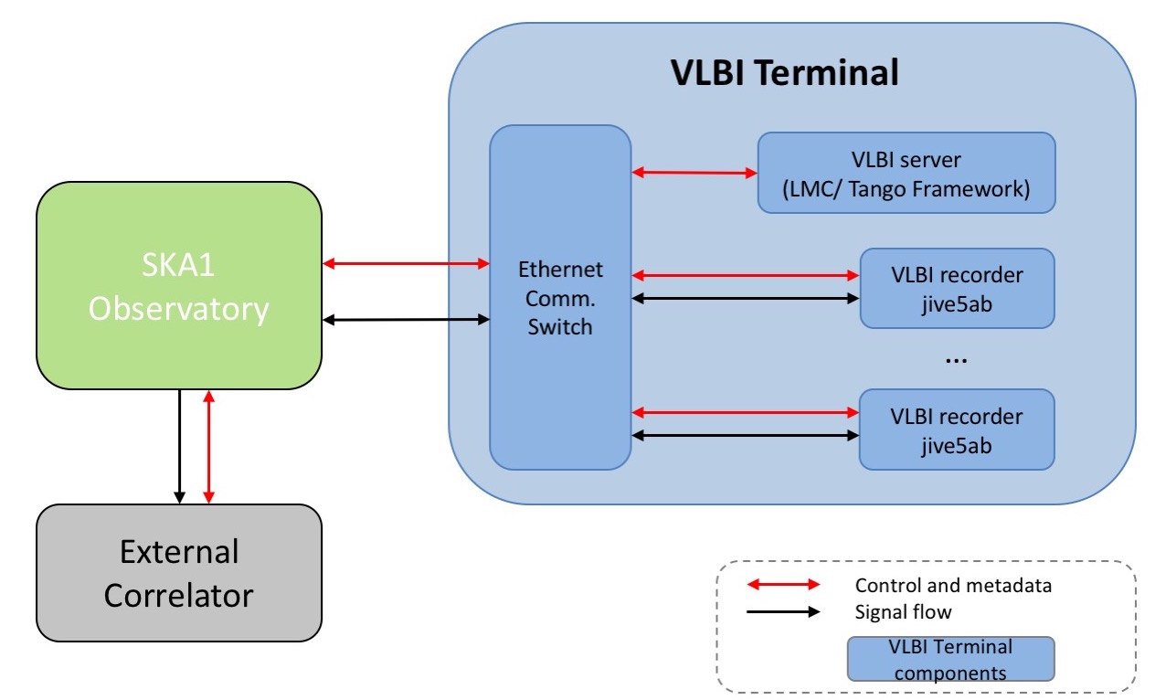
The VLBI terminal will be comprised of a Commercial Off-The-Shelf (COTS) VLBI server, a COTS 100GE Ethernet Switch and one or several COTS VLBI recorders (Fig. 6). The exact number of recorders depends on the recorder performance and on the required recording data rate, with the aim of supporting 400 Gbps (MID) and 100 Gbps (LOW) maximum data rates from the SKA1 telescopes with the agreed interfaces. The data rate could easily surpass this planned capability, mainly for MID Band 5, therefore the VLBI equipment and interfaces will be upgraded during the lifetime of the SKA Observatory.
The Ethernet switch will provide bi-directional communication with the SKA1 Observatory and from there, with the outside world. The ethernet switch will receive the VLBI VDIF packets from the SKA correlators, and either send them to the External correlator in real-time for e-VLBI observing or stream them to the VLBI recorders for subsequent playback at a convenient time. It will also communicate with the Telescope Manager for monitor and control tasks and subscription to metadata. The communication with the outside world also provides access for developers for maintenance tasks and upgrades.
The VLBI VDIF recorders selected for this design are FlexBuff type recorders but other types of compatible VDIF recorders may be used in conjunction, or as an alternative (e.g. Mark 6 Haystack recorders or NAOJ OCTAVE-families). FlexBuff recorders provide a flexible and standard COTS solution for simultaneous receive, buffer (record) and transmission of VLBI data streams. Requirements for a FlexBuff vary depending on the buffer capacity and the sustained data rate that needs to be achieved [6]. The VLBI recorders will be controlled using the jive5ab open source control software [7].
The VLBI server will implement SKA1 Local Monitoring and Control (LMC) within the Tango open source framework adopted by the SKA1 Observatory. The LMC will be responsible for Monitor and Control of the VLBI terminal and for subscription to the appropriate metadata, as well as logging events and sending alarms to the Telescope Manager. The VLBI server will implement an additional bespoke application to extract the metadata and generate the observing experiment log required by the External correlator that will be recorded in the FlexBuff recorders along with the data. The LMC will also implement a translator for jive5ab commands to control the recorders and use standard Tango translators for the Linux server and the Ethernet switch.
4 SKA-VLBI Science Use Cases
The SKA1 Scientific Use Cases document [8] contains six science use cases that request the SKA-VLBI capability (out of a total of 58 cases). These were formulated before the detailed VLBI implementation was known. It is time to reconsider and update some of these use cases, as well as other, new use cases that could exploit the unique SKA-VLBI capabilities. Notably, there are no use cases for the SKA1-LOW telescope, because VLBI was not considered for this telescope in the early days of the project. This is because of the limited number of other telescopes available in the 50-350 MHz frequency range. JUMPING JIVE is engaging with the SKA Science Working Groups, Focus groups, and members of the VLBI community for the preparation of additional VLBI science cases that properly reflect the recent evolution of high-profile VLBI science with a view to exploit the full capability of the SKA1 telescopes.
The “SKA General Science meeting and Key Science Workshop” (April 8-12, 2019) and the “SKA-VLBI Key Science Projects and Operations Workshop” (October 14-17, 2019) will be ideal forums for discussions towards the inclusion of VLBI science in the future SKA Key Science Projects [2].
Acknowledgments.
The “VLBI with the SKA” work package is part of the JUMPING JIVE project, that has received funding from the European Union’s Horizon 2020 research and innovation programme under grant agreement No 730884.References
- [1] Z. Paragi, L. Godfrey, C. Reynolds et al., Very Long Baseline Interferometry with the SKA, Proceedings of Science, PoS[AASKA14]143, 2015
- [2] Z. Paragi, A. Chrysostomou, C. García-Miró, SKA-VLBI Key Science Programmes, these proceedings
- [3] R.C. Bolton, A. Chrysostomou, G.R. Davis et al., SKA1 Operational Concept Document, SKA-TEL-SKO-0000307, Rev 3, 2018
- [4] P. Dewdney, W. Turner, R. Braun et al., SKA1 System Baseline Design, SKA-TEL-SKO-0000002, Rev 3, 2016
- [5] M. Caiazzo, SKA Phase 1 System Requirements Specification, SKA-TEL-SKO-0000008, Rev 11, 2017
- [6] E.Turtiainen, M. Uunila, A. Mujunen, J. Ritakari, Hardware design document for simultaneous I/O storage elements, NEXPReS Deliverable D8.2, http://www.jive.nl/nexpres/lib/exe/fetch.php?media=nexpres:2011-02-28_wp8-d8.2.pdf, 2011
- [7] H. Verkouter, Jive5ab command set 1.10, http://www.jive.nl/ verkout/evlbi/jive5ab-documentation-1.10.pdf, 2018
- [8] J. Wagg, SKA1 Scientific Use Cases, SKA-TEL-SKO-0000015, Rev 3, 2016