Visual Cue Integration for Small Target Motion Detection in Natural Cluttered Backgrounds ††thanks: This work was supported in part by EU FP7 Project HAZCEPT under Grant 318907, in part by HORIZON 2020 project STEP2DYNA under Grant 691154, in part by HORIZON 2020 project ULTRACEPT under Grant 778062, and in part by the National Natural Science Foundation of China under Grant 11771347.
Abstract
The robust detection of small targets against cluttered background is important for future artificial visual systems in searching and tracking applications. The insects’ visual systems have demonstrated excellent ability to avoid predators, find prey or identify conspecifics – which always appear as small dim speckles in the visual field. Build a computational model of the insects’ visual pathways could provide effective solutions to detect small moving targets. Although a few visual system models have been proposed, they only make use of small-field visual features for motion detection and their detection results often contain a number of false positives. To address this issue, we develop a new visual system model for small target motion detection against cluttered moving backgrounds. Compared to the existing models, the small-field and wide-field visual features are separately extracted by two motion-sensitive neurons to detect small target motion and background motion. These two types of motion information are further integrated to filter out false positives. Extensive experiments showed that the proposed model can outperform the existing models in terms of detection rates.
Index Terms:
Small target motion detection, neural modelling, visual cue integration, cluttered background.I Introduction
As processing power increases exponentially, and as sensors becomes less costly and more reliable, robots have shown great potential in reshaping human life in the future [1, 2, 3, 4, 5]. Intelligent robots embedded with artificial visual systems will be able to cope with dynamic visual worlds in real-time and perform required tasks without human intervention [6, 7, 8, 9, 10]. Among a number of visual functionalities, detecting objects of interest in the distance and early could help a robot achieve dominant position in competition, defence, and survive. However, artificial visual systems are still far from acceptable to robustly and cheaply detect moving objects in the distance against cluttered natural backgrounds.
In the visual world, detecting object motion which is far away from the observer, often means dealing with small dim speckles in the field of view. The difficulty of small target motion detection is reflected in: first, the sizes of small targets may vary from one pixel to a few pixels, whereas other physical characteristics, such as color, shape and texture, are difficult to recognize and cannot be used for motion detection. Second, the natural background is extremely cluttered and contains a number of small-target-like features. In addition, free motion of camera would bring further difficulties to small target motion detection.
For animals, such as insects, the ability to detect small targets against cluttered backgrounds is important, serving to search for mates and track prey. Evolved over millions of years, the small target detection visual systems in insects are both efficient and reliable. As an example, dragonflies can pursue small flying insects with successful capture rates as high as relying on their well evolved visual systems [11]. The exquisite sensitivity of insects for small moving targets is coming from a class of specific neurons, called small target motion detectors (STMDs) [12]. The STMD neurons give peak responses to small targets subtending of the visual field, with no response to large bars (typically ) or to background movements represented by wide-field grating stimuli [13]. This makes the STMD an ideal template to develop specialized artificial visual systems for small target motion detection.
The electrophysiological knowledge about the STMD neuron revealed in the past few decades, makes it possible to propose quantitative models. Wiederman et al. [14] presented an elementary STMD (ESTMD) to account for size selectivity of the STMD neurons. However, the ESTMD did not consider direction selectivity and is unable to estimate motion direction of small targets. To address this issue, some directionally selective STMD models have been developed, including two hybrid models [15, 16], and directionally selective STMD (DSTMD) [17]. These STMD-based models take advantage of small-field visual features for small target motion detection, while ignore other visual cues, such as wide-field features. Due to this, the models cannot discriminate small target motion from false positive background motion, and their detection results often contain a large number of noises. In order to eliminate the background false positives, the wide-field features should not be disregarded, which can be combined with the small-field cues in small target motion discrimination.
In the insects’ visual systems, the motion of wide-field features can elicit strong responses of an identified interneuron called lobula plate tangential cell (LPTC) [18]. In the further research [19], Nicholas et al. assert that the wide-field motion and small target motion which are separately detected by the LPTCs and STMDs, are integrated in target-selective descending neurons (TSDNs). More precisely, the responses of the STMDs are largely suppressed by the LPTCs when the small object and background move at the similar velocities. These biological findings provide a solution for designing artificial visual systems to filter out false positives in small target motion detection.
Inspired by the above biological findings, this paper proposes a visual system model (TSDN) for small target motion detection in cluttered moving backgrounds. The visual system is composed of an STMD subsystem for small target motion detection and an LPTC subsystem for wide-field motion perception. The outputs of the STMD and LPTC are integrated to discriminate small targets from background false positives. The rest of this paper is organized as follows. In Section II, we introduce our proposed visual system model. Section III provides extensive performance evaluation as well as comparisons against the existing models. Finally, we conclude this paper in Section IV.
II Methods
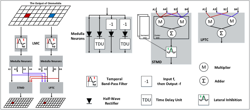
As illustrated in Fig. 1, our developed visual system is composed of ommatidia, large monopolar cells (LMCs) [20], medulla neurons (including Tm1, Tm2, Tm3, and Mi1) [21], STMDs, LPTCs and TSNDs. Luminance signals are received and smoothed by the ommatidia, then applied to the LMCs where lumninace changes of each pixel over time are extracted. These luminance change signals are further separated into luminance increase and decrease components by the medulla neurons, which are fed into the STMDs and LPTCs for detecting small target motion and wide-field motion, respectively. The TSDNs integrate the extracted motion information to filter out the background false positives. The schematic illustration of the proposed visual system model is presented in Fig. 2 which will be elaborated in the following.
II-A Ommatidia
The first layer of the developed visual system is the ommatidia arranged in a matrix; the luminance of each pixel in the input image is captured and smoothed by each ommatidium which is modelled as a spatial Gaussian filter. Let denote the input image sequence, where and are spatial and temporal field positions. The output of an ommatidium is given by,
| (1) |
where is a Gaussian function, defined as
| (2) |
II-B Large Monopolar Cells

As shown in Fig. 2, the output of the ommatidia forms the input to LMCs in the next layer. Each LMC is modelled as a temporal band-pass filter to extract luminance changes over time caused by motion. The impulse response of the band-pass filter is defined as the difference of two Gamma kernels, then the output of each LMC can be given by,
| (3) | ||||
| (4) |
where stands for the Gamma kernel [22], defined as
| (5) |
where and represents the order and time constant of Gamma kernel.
II-C Medulla Neurons
As can be seen from Fig. 2, the output of LMCs is applied to the medulla neurons including Tm1, Tm2, Tm3, and Mi1, which constitute four parallel signal-processing channels. The Tm3 and Tm2 are modelled as half-wave rectifiers to separate into luminance increase and decrease components. Let and denote the output of the Tm3 and Tm2, respectively, then they are given by
| (6) | ||||
| (7) |
where denotes . The Mi1 and Tm1 further temporally delay and by convolving them with a Gamma kernel. That is,
| (8) | ||||
| (9) |
where and represent the outputs of the Mi1 and Tm1, respectively; and are the order and time constant of the Gamma kernel, which separately determine the time-delay order and length.
II-D Small Target Motion Detectors
As illustrated in Fig. 2, the outputs of the medulla neurons are collected by the STMDs for small target motion detection against cluttered moving backgrounds. The existing DSTMD model [17] is adopted to describe the STMDs, where the output of each STMD is defined by the multiplication of medulla neural outputs from two different pixels to produce strong responses to moving objects. That is,
| (10) |
where denotes the preferred direction of the STMD neuron; is defined as
| (11) |
where is a constant.
In order to suppress the responses to the large moving objects, the is laterally inhibited by convolving with an inhibition kernel . That is,
| (12) |
where represents the inhibited signal; the inhibition kernel is defined as
| (13) | ||||
| (14) |
where and respectively denote and ; , , and are constant.
The output of STMDs can be used to determine the positions of small moving targets by comparing it with a threshold . Specifically, if is higher than , then we believe that a small object moving along direction is located at pixel and time .
II-E Lobula Plate Tangential Cells
Although the LPTC also gather the outputs of medulla neurons, it serves to detect wide-field motion rather than small target motion. The LPTC is modelled by the existing two-quadrant-detector (TQD) [23, 24], and its output is defined as
| (15) |
where stands for the preferred direction of the LPTC neuron.
The output of LPTCs reveals the motion of normal-size objects embedded in the cluttered background such as trees, rocks and bushes. More precisely, for a threshold , if , then we believe that a background object moving along direction is detected at pixel and time .
II-F Target-Selective Descending Neurons
The TSDN receives two types of neural outputs, including the output of STMDs and the output of LPTCs . These neural outputs are integrated to filter out background false positives via the following two steps.
1) Background Motion Direction Estimation: The output of LPTCs is used to estimate the motion direction of the background. The basic idea is using the motion direction of most background objects to represent that of the background. That is,
| (16) |
where denotes the motion direction of the background at time .
2) False Positive Elimination: As revealed in the biological research [19], the output of STMDs is largely inhibited by the output of LPTCs when the target and background move in the same direction. That is, the excitatory flow from the STMDs and inhibition from the LPTCs are summed by the TSDNs using the following:
| (17) |
where refers to the output of TSDNs and , if ; otherwise, .
It is worthy to note that the false positives are often caused by the motion of objects embedded in the background, which means their motion directions are consistent with that of the background. In the (17), the responses of STMDs will deduct the outputs of LPTCs, if the motion direction of the detected object equals to that of the background . That is, the responses to the false positives will decrease, resulting in the improvement of detection performances.
II-G Parameter Setting
Parameters of the proposed visual system model are listed in Table I. Based on the previous parameter analysis and test [17, 24, 5, 25], the parameters are tuned manually to make the developed model satisfy the basic neural properties, which are mainly determined by target velocity and size. They will not be changed in the following experiments unless stated.
The proposed visual system model is written in Matlab (The MathWorks, Inc., Natick, MA). The computer used in the experiments is a standard laptop with a GHz Intel Core i7 CPU and GB DDR3 memory.
III Results
The developed visual system model is evaluated on a dataset which is produced by Vision Egg [26]. The image sequences in the dataset are all synthesized by using real natural background images and a computer-generated small target with different sizes, velocities and luminance. The video images are (in horizontal) by (in vertical) pixels and temporal sampling frequency is set as Hz.
In order to quantitatively evaluate the detection performance, two metrics are defined as following [27],
| (18) | ||||
| (19) |
where and denote detection rate and false alarm rate, respectively. The detected result is considered correct if the pixel distance between the ground truth and the result is within a threshold ( pixels).
III-A Differences of the STMD and LPTC
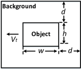
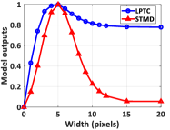
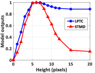
In the proposed visual system model, the STMD and LPTC are applied to detect small target motion and background motion, respectively. To further demonstrate the differences between the STMD and LPTC, we compare their outputs to objects with different velocities, widths, heights and Weber contrast. As shown in Fig. 3, width (or height) represents object length extended parallel (or orthogonal) to the motion direction. Weber contrast is defined by the following equation,
| (20) |
where is the average pixel value of the object, while is the average pixel value in neighboring area around the object. If the size of a object is , the size of its background rectangle is , where is a constant which equals to pixels. The initial Weber contrast, velocity, width and height of the object are set as , pixel/second, pixels and pixels, respectively.
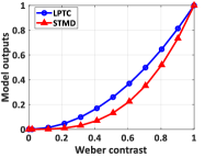
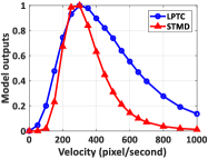
Fig. 4(a) shows the STMD and LPTC outputs with respect to the Weber contrast. As can be seen, both the STMD and LPTC outputs increase as the increase of Weber contrast, until reach maximum at Weber contrast . This indicates that the higher Weber contrast of an object is, the easier it can be detected. Fig. 4(b) presents the two neural outputs with regard to the velocity of the moving object. Obviously, the STMD and LPTC outputs peak at an optimal velocity ( pixel/s). These two neurons also exhibit high responses to the objects whose velocities range from to pixel/s. Fig. 4(c) and (d) display the outputs of the STMD and LPTC when changing the width and height of the object. As it is shown, both the STMD and LPTC outputs have a local maximum at width (or height ). After reaching the local maximum, the STMD output decreases significantly as the increase of target width (or height), and tends to be stable around (or for height). In contrast, the LPTC output has a slight drop and stabilizes at (or for height). The above results indicate that the STMD prefers small moving objects whose widths and heights are smaller than pixels, while the LPTC shows little preference for the target’s width and height and can detect moving objects with normal sizes in the backgrounds.
III-B Effectiveness of the TSDN
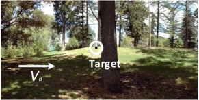
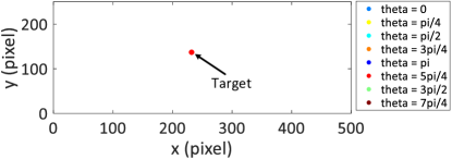
In the proposed visual system model, the TSDNs integrate small target motion from STMDs with background motion from LPTCs to filter out background false positives. To validate its effectiveness, we compare the performances of the TSDNs and STMDs. The testing setups are detailed as follows: the input image sequence is presented in Fig. 5(a), which displays a small target moving against the cluttered background; the background is moving from left to right and its velocity is pixel/s; the luminance, size and velocity of small target are equal to , pixels and pixel/s, respectively; the position and motion direction of the small target at time ms is illustrated in Fig. 5(b)
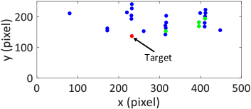
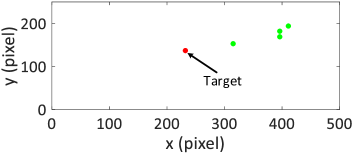
Fig. 6(a)-(b) displays the positions and motion directions of the small objects detected by the STMDs and TSDNs where the detection threshold is set as . As shown in Fig. 6(a), the detection result of the STMDs contains a number of false positives whose motion directions are consistent with that of the background, i.e., the blue points. After being suppressed by the output of the LPTCs, these false positives moving with the background are all filtered out [see Fig. 6(b)].
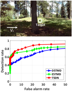
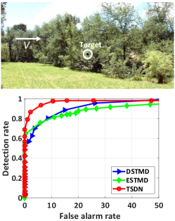
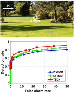
We further conduct a performance comparison between the developed TSDN and two existing models including ESTMD [14] and DSTMD [17]. Three image sequences with different backgrounds are used for experiments, as displayed in Fig. 7(a)-(c). In these videos, the backgrounds are all moving from left to right and its velocity is pixel/s. A small target whose luminance, size are set as and pixels, is moving against cluttered backgrounds. The coordinate of the small target at time is ms.
Fig. 7(a)-(c) show the receiver operating characteristics (ROC) curves of the three models for the three image sequences. It can be seen that the TSDN has better performance than the DSTMD and ESTMD. More precisely, the TSDN has higher detection rates () compared to the DSTMD and ESTMD while the false alarm rates are low.
IV Conclusion
In this paper, we have proposed a visual system model (TSDN) for small target motion detection in cluttered backgrounds. The visual system contains two motion-sensitive neurons and is capable of filtering out the background false positives. The first neuron callled the STMD, is intended to detect small moving targets and their motion directions. The second neuron called the LPTC, is designed to perceive background motion and estimate background motion direction. The TSDN is introduced to integrate the small target motion and background motion to suppress false positives. Comprehensive evaluation on the dataset, and comparisons with the existing STMD models demonstrate the effectiveness of the proposed visual system with lower false positives.
References
- [1] S. Yue and F. C. Rind, “Collision detection in complex dynamic scenes using an lgmd-based visual neural network with feature enhancement,” IEEE Trans. Neural Netw., vol. 17, no. 3, pp. 705–716, May 2006.
- [2] Q. Fu, C. Hu, J. Peng, and S. Yue, “Shaping the collision selectivity in a looming sensitive neuron model with parallel on and off pathways and spike frequency adaptation,” Neural Netw., Apr. 2018.
- [3] C. Hu, F. Arvin, C. Xiong, and S. Yue, “A bio-inspired embedded vision system for autonomous micro-robots: the lgmd case,” IEEE Trans. Cogn. Develop. Syst., vol. 9, no. 3, pp. 241–254, Sep. 2016.
- [4] H. Wang, J. Peng, P. Baxter, C. Zhang, Z. Wang, and S. Yue, “A model for detection of angular velocity of image motion based on the temporal tuning of the drosophila,” in Proc. Int. Conf. Artif. Neural Netw., Rhodes, Greece, 2018, pp. 37–46.
- [5] H. Wang, J. Peng, and S. Yue, “A feedback neural network for small target motion detection in cluttered backgrounds,” in Proc. Int. Conf. Artif. Neural Netw., Rhodes, Greece, 2018, pp. 728–737.
- [6] S. Yue, F. C. Rind, M. S. Keil, J. Cuadri, and R. Stafford, “A bio-inspired visual collision detection mechanism for cars: Optimisation of a model of a locust neuron to a novel environment,” Neurocomputing, vol. 69, no. 13, pp. 1591–1598, Feb. 2006.
- [7] B. Hu, S. Yue, and Z. Zhang, “A rotational motion perception neural network based on asymmetric spatiotemporal visual information processing,” IEEE Trans. Neural Netw. Learn. Syst., vol. 28, no. 11, pp. 2803–2821, Nov 2016.
- [8] S. Yue and F. C. Rind, “Redundant neural vision systems-competing for collision recognition roles,” IEEE Trans. Auton. Mental Develop., vol. 5, no. 2, pp. 173–186, Apr. 2013.
- [9] Q. Fu and S. Yue, “Modeling direction selective visual neural network with on and off pathways for extracting motion cues from cluttered background,” in Proc. IEEE Int. Joint Conf. Neural Netw., Anchorage, AK, USA, 2017, pp. 831–838.
- [10] Z. Song, J. Zhang, G. Shi, and J. Liu, “Fast inference predictive coding: A novel model for constructing deep neural networks,” IEEE Trans. Neural Netw. Learn. Syst., to be published, doi: 10.1109/TNNLS.2018.2862866.
- [11] R. Olberg, A. Worthington, and K. Venator, “Prey pursuit and interception in dragonflies,” J. Comp. Physiol. A, vol. 186, no. 2, pp. 155–162, Feb. 2000.
- [12] D. O’Carroll, “Feature-detecting neurons in dragonflies,” Nature, vol. 362, no. 6420, pp. 541–543, Apr. 1993.
- [13] K. Nordström, “Neural specializations for small target detection in insects,” Curr. Opin. Neurobiol., vol. 22, no. 2, pp. 272–278, Apr. 2012.
- [14] S. D. Wiederman, P. A. Shoemaker, and D. C. O’Carroll, “A model for the detection of moving targets in visual clutter inspired by insect physiology,” PLoS One, vol. 3, no. 7, p. e2784, Jul. 2008.
- [15] S. D. Wiederman and D. C. O’Carroll, “Biologically inspired feature detection using cascaded correlations of off and on channels,” J. Artif. Intell. Soft Comput. Res., vol. 3, no. 1, pp. 5–14, Dec. 2013.
- [16] Z. M. Bagheri, S. D. Wiederman, B. S. Cazzolato, S. Grainger, and D. C. O’Carroll, “Performance of an insect-inspired target tracker in natural conditions,” Bioinspir. & Biomim., vol. 12, no. 2, p. 025006, Feb. 2017.
- [17] H. Wang, J. Peng, and S. Yue, “A directionally selective small target motion detecting visual neural network in cluttered backgrounds,” IEEE Trans. Cybern., to be published, doi: 10.1109/TCYB.2018.2869384.
- [18] A. Borst, M. Egelhaaf, and J. Haag, “Mechanisms of dendritic integration underlying gain control in fly motion-sensitive interneurons,” J. Comput. Neurosci., vol. 2, no. 1, pp. 5–18, Mar. 1995.
- [19] S. Nicholas, J. Supple, R. Leibbrandt, P. T. Gonzalez-Bellido, and K. Nordström, “Integration of small-and wide-field visual features in target-selective descending neurons of both predatory and non-predatory dipterans,” Journal of Neuroscience, pp. 1695–18, 2018.
- [20] R. R. Harrison, “A low-power analog vlsi visual collision detector.” in Proc. NIPS, Vancouver, BC, Canada, 2003, pp. 987–994.
- [21] R. Behnia and C. Desplan, “Visual circuits in flies: beginning to see the whole picture,” Curr. Opin. Neurobiol., vol. 34, pp. 125–132, Oct. 2015.
- [22] B. De Vries and J. C. Príncipe, “A theory for neural networks with time delays,” in Proc. NIPS, 1990, pp. 162–168.
- [23] H. Eichner, M. Joesch, B. Schnell, D. F. Reiff, and A. Borst, “Internal structure of the fly elementary motion detector,” Neuron, vol. 70, no. 6, pp. 1155–1164, Jun. 2011.
- [24] H. Wang, J. Peng, and S. Yue, “An improved lptc neural model for background motion direction estimation,” in Proc. IEEE Conf. ICDL-EpiRob, Lisbon, Portugal, 2017, pp. 47–52.
- [25] ——, “Bio-inspired small target motion detector with a new lateral inhibition mechanism,” in Proc. Int. Joint Conf. Neural Netw. (IJCNN), Vancouver, BC, Canada, 2016, pp. 4751–4758.
- [26] A. D. Straw, “Vision egg: an open-source library for realtime visual stimulus generation.” Front. Neuroinf., vol. 2, no. 4, Nov. 2008.
- [27] C. Gao, D. Meng, Y. Yang, Y. Wang, X. Zhou, and A. G. Hauptmann, “Infrared patch-image model for small target detection in a single image,” IEEE Trans. Image Process., vol. 22, no. 12, pp. 4996–5009, Sep. 2013.