Extreme high field plasmonics: electron acceleration and XUV harmonic generation from ultrashort surface plasmons
Abstract
Experiments on the excitation of propagating surface plasmons (SPs) by ultrashort, high intensity laser interaction with grating targets are reviewed. At intensities exceeding on target, i.e. in the strongly relativistic regime of electron dynamics, multi-MeV electrons are accelerated by the SP field as dense bunches collimated in a near-tangent direction. By the use of a suitable blazed grating, the bunch charge can be increased up to 660 picoCoulomb. Intense XUV high harmonics (HHs) diffracted by the grating are observed when a plasma with sub-micrometer scale is produced at the target surface by a controlled prepulse. When the SP is excited, the HHs are strongly enhanced in a direction quasi-parallel to the electrons. Simulations suggest that the HHs are boosted by nanobunching in the SP field of the electrons which scatter the laser field. Besides the static and dynamic tailoring of the target density profile, further control of electron and HH emission might be achieved by changing the SP duration using a laser pulse with rotating wavefront. This latter technique may allow to produce nearly single-cycle SPs.
I Introduction
Plasmonics is the study and exploitation of collective electron excitations, commonly referred to as plasmons, in solid density materials. Most plasmonics is actually based on surface modes, which exist at the boundary between two different media (including the case in which one medium is the vacuum), and can be both localized and propagating, the latter being known as surface plasmon polaritons (SPPs). Central to plasmonics is the coupling between surface plasmons and electromagnetic (EM) waves in vacuum, i.e. laser light irradiating the material.
Despite the apparent common ground between plasmonics and plasma physics, the interaction between the two research communities has been limited, as wisely recognized by G. Manfredi in his EditorialManfredi (2018) opening the Special Topic issue on “Plasmonics and solid state plasmas” in this journal. When considering plasmonics as part of solid state physics one argues that it has to deal with the quantum theory of condensed matter, while for most of “traditional” plasma physics a classical approach is adequate because of the high energy density. So viewing plasmonics and plasma physics as well separated areas might be considered as natural. However, the key concepts of surface and bulk plasmons and of their coupling with light can be described and modeled within classical electrodynamics. Hence, there is a potential overlap between plasmonics and laser-plasma interactions – to be more specific, the research area of the interaction of high-intensity, femtosecond laser pulses with solid targets. In fact, while the short duration of the pulse preserves the high density and the sharp target-vacuum interface (both necessary to the surface plasmon excitation), the laser field strength allows to create free electrons by instantaneous field ionization, so that any material behaves similarly to a simple metal, i.e. a collisionless plasma, and can sustain surface plasmons over a broad range of frequencies.
One may also argue that plasmonics is oriented towards the development of advanced applications, such as sensors and optical devices, which require a level of control and reliability on the system that is far from the typical conditions of laser-plasma interaction experiments. It is true that a classical high-temperature plasma is somewhat a “wild” enviroment which is affected by various instabilities and nonlinear effects making its dynamics difficult to control, but this very general issue did not prevent the development of many successful plasma-based technologies. Moreover, the control and reproducibility of intense laser-plasma interaction phenomena has often been limited to imperfections of high power laser systems, most of which have become less severe thanks to recent developments. A good example, of direct relevance for the contents of the present paper, is provided by early attempts of exciting surface plasma waves (i.e. SPPs in a simple metal, from now on referred to simply as surface plasmons or SPs) by irradiating solid targets with intense femtosecond pulsesGauthier et al. (1995). In this regime, the linear coupling of SPs with laser light requires a target with a periodical surface modulation, i.e. a grating. High power femtosecond pulses, amplified via the Nobel prize–awarded Chirped Pulse Amplification techniqueStrickland and Mourou (1985), are typically accompanied by both short prepulses and long pedestals preceding the main short pulse: these spurious emissions may be intense enough to damage and pre-ionize the target, causing early plasma formation and pre-expansion able to destroy a shallow modulation at the surface. This issue has limited experiments on high-intensity interaction with structured targets, and thus on high field SP excitationKahaly et al. (2008); Hu et al. (2010); Bagchi et al. (2012) to moderate intensities for a long time. Recently, the development of “pulse cleaning” techniques such as the ionization shutter or plasma mirrorKapteyn et al. (1991); Dromey et al. (2004); Lévy et al. (2007); Thaury et al. (2007) delivered pulses with extremely high values of pulse-to-prepulse intensity ratio, briefly named as contrast. This achievement makes now possible to investigate the interaction of the most intense pulses available today with targets having sub-micrometer thickness and structuring.
In a series of experiments performed with the UHI100 laser at the SLIC facility of CEA Saclay in France, our group has investigated the interaction of high intensity (), short duration ( fs), ultrahigh contrast pulses with grating targets. Noticeably, the laser frequency and intensity are such that the electron dynamics is strongly relativistic. In these conditions, the properties of SPs are not well known. As a matter of fact, all the assumptions underlying the simple linear theory of SPs break downMacchi (2018). However, these experiments provided strong evidence of SP-enhanced emission of energetic particles such as protonsCeccotti et al. (2013), electronsFedeli et al. (2016) and photons as extreme ultraviolet (XUV) harmonics of the incident laserCantono et al. (2018a). Hence, these observations may stimulate theoretical advances in nonlinear plasmonics as well.
In the most recent experiments, we showed that features of electron and XUV harmonic emissions can be enhanced by, respectively, shaping the grating profileCantono et al. (2018b) and smoothing the density gradient using a femtosecond prepulseCantono et al. (2018a). Both cases confirm that the high-contrast interaction is sensitive to the target density profile at a sub-micrometer scale and show the possibility of improved control of the latter.
The results on XUV emission, supported by detailed simulationsCantono et al. (2018a), enlighted a new mechanism of harmonic generation which is strongly correlated with electron acceleration by the SP. The harmonic emission is enhanced by nanobunching of electrons trapped in the SP field, which is somewhat reminiscent of the collective beam instability in a free electron laserPellegrini, Marinelli, and Reiche (2016). The mechanism thus represents a novel example of exploiting self-organization and nonlinear dynamics to develop a plasma-based device or technology.
Secondary emissions from femtosecond laser-irradiated solid targets are characterized by the ultrashort duration, which is of the order of the laser pulse duration at the source. For specific applications it is desirable to push the source duration down to the attosecond regime, a goal partly reached in the case of XUV harmonics which constitute a train of sub-femtosecond spikes. Inspired by a scheme for the spatial separation of the spikesWheeler et al. (2012); Vincenti and Quéré (2012), we proposed a scheme for the excitation of extremely short SPs with duration approaching the single-cycle limitPisani, Fedeli, and Macchi (2018). The concept exploits the wavefront rotation (WFR) of a short laser pulseQuéré et al. (2014), which is another possible control parameter of the interaction. Near-single-cycle SPs might be of interest for applications in both ordinary and high-field plasmonicsMacDonald et al. (2009); Dombi et al. (2010); Krüger, Schenk, and Hommelhoff (2011); Rácz et al. (2011); Li et al. (2013); Polyakov et al. (2013).
In the remainder of the paper, after briefly recalling the basics of SP excitation by laser coupling with a grating we review the above mentioned results on electron acceleration and XUV harmonic generation. We also include a discussion of the simple modeling of electron acceleration in the SP field and of SP generation using a pulse with WFR. Other SP-driven effects such as enhanced heating and proton acceleration or the analysis of SP excitation in a grating target are discussed in detail in previous papersCeccotti et al. (2013); Sgattoni et al. (2016); Macchi (2018) and references therein.
II Surface plasmon excitation in gratings
In this section we summarize the basics of SP excitation by a laser pulse impinging on a grating, commenting on specific issues of the high field regime. We consider the interface between vacuum and a cold plasma or simple metal with dielectric function , where is the plasma frequency and the electron density. The dispersion relation of SPs is
| (1) |
provided that . Eq.(1) prevents phase matching of the SP with an obliquely incident EM plane wave because the latter has a wavevector component parallel the surface equal to , with the angle of incidence, thus . However, if the surface is modulated with period , the SP dispersion relation is replicated long the -axis with period or, equivalently, folded into the Brillouin zone (Floquet–Bloch theorem), so that intersections with the EM dispersion relation are now possible. This grating coupling scheme is not the only one used in ordinary plasmonics Maier (2007) but it is the one that appears most suitable when exciting SPs with intense laser pulses. In fact, when using prism-based schemes (e.g. Kretschmann or Otto configurations) the intense laser pulse would propagate through layers of dielectric material, thus undergoing distortions by nonlinear effects and ionization. Given the grating period , the resonant excitation of SPs occurs at incidence angles such that
| (2) |
where is the wavelength in vacuum and is an integer. Notice that the SP may also propagate in the direction opposite to the impinging pulse.
Eq.(2) assumes that the dispersion relation (1) is not strongly modified by the surface modulation, which is a good approximation for shallow gratings since deviations are of the order with the grating depth. In the case of our experiments the gratings are not extremely shallow, since and , a choice made to preserve the grating against hydrodynamical expansion. At this stage, however, it is not important to take such corrections into account since Eq.(1) may be already considered as an approximation in the high field regime, because nonlinear and kinetic effects have also been neglected.
In a solid density material and for optical frequencies , so that Eq.(2) may be simplified as , which is equivalent to the condition that the -th diffraction order from the grating is along the surface. This observation can be useful when one considers that in experiments with superintense, tightly focused laser pulses, only a few periods of the grating are illuminated, and the assumption of an infinite periodic medium becomes questionable. However, one may also think to the SPs as excited by the laser light scattered by the grating in conditions of constructive interference, and argue that the finite spot size may affect the resonance width.
III Electron acceleration by surface plasmons
In the low field regime, plasmonic-enhanced emission of photoelectrons has been widely studied with regard to the development of ultrafast photocathodesTsang, Srinivasan-Rao, and Fischer (1991); Dombi and Rácz (2008); Hwang, Vorobyev, and Guo (2009); Rácz et al. (2011); Watanabe, Inami, and Kawata (2011); Li et al. (2013); Gong et al. (2014); Ono et al. (2015). In the case of laser-grating interactions, some experiments found photoelectrons of anomalously high energy, attributed to ponderomotive acceleration in the evanescent SP fieldZawadzka et al. (2001); Kupersztych, Monchicourt, and Raynaud (2001); Kupersztych, Raynaud, and Riconda (2004); Irvine, Dechant, and Elezzabi (2004); Irvine and Elezzabi (2006). The features of electron acceleration emerging in the case of high field, relativistically strong interactions are qualitatively different from such previous observations.
III.1 Experimental observation
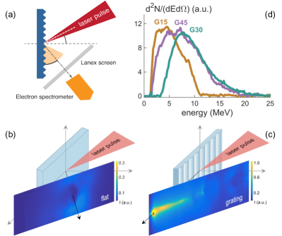
The most striking effect observed in the experiments is the acceleration of collimated bunches of multi-MeV electrons on the vacuum side in a near tangent direction when the gratings are irradiated at the angle of incidence for which excitation of a SP is expectedFedeli et al. (2016). Fig.1 summarizes the basic set-up and the main results of devoted experiments at SLIC (details can be found in Refs.Fedeli et al., 2016; Cantono et al., 2018b). The 25 fs duration, 0.8 m wavelength laser pulse of the UHI-100 laser was focused by a parabola on gratings of different spatial period . The pulse-to-prepulse contrast was and at, respectively, 20 and 5 ps before the main pulse.
For all the gratings, the electron spectra near the resonant angle are broad but strongly non-thermal, peaking at energies of MeV and extending up to the highest detectable value of MeV for laser intensities in the range of . This corresponds to a dimensionless intensity parameter
| (3) |
which indicates that the interaction is in the relativistic regime (). The electrons are emitted at grazing incidence, typically within an angle of from the target tangent. Detailed measurements show that the electrons are collimated in a cone of aperture for all gratings, and that the charge flux exceeds nC/sr values. By varying the incidence angle of around the resonant value, the peak energy, charge and collimation of the electrons decrease by at least a factor of .
The above findings are in sharp contrast with the electron emission from flat targets, which is spatially diffuse and limited to sub-MeV energies, below the detection threshold of the spectrometer. Such low energies are consistent with the estimate based on the so-called ponderomotive energy in the investigated energy range,
| (4) |
III.2 Simple model
A simple model highlights the mechanism of electron acceleration by SP and provides an estimate for the attainable energy and the angle of emission. The model is similar to that used in the famous paper by Tajima and DawsonTajima and Dawson (1979) on electron acceleration in wake plasma waves, the main difference being the essential two-dimensional (2D) nature of the SP.
We consider a SP propagating in the laboratory frame along the surface of a step-boundary plasma with the density profile (i.e. the vacuum region is ). Assuming the SP to propagate along with phase velocity as given by the dispersion relation (1) (in this section we write for since no confusion is possible), the SP fields have the form with
| (5) | |||||
| (6) | |||||
| (7) |
where and , and is the amplitude of the longitudinal electric field() component at . Notice that and are continuous at while is discontinuous, which implies a surface charge density .
We now perform a Lorentz transformation to the frame moving with along (so that ). In this frame, the phase with and , and the fields do not depend on time. The field amplitudes transform according to , , , and thus we obtain
| (8) | |||||
| (9) | |||||
| (10) | |||||
Notice that and that the magnetic field in vanishes for and is discontinuous at the surface. This is consistent with the transformation of the surface charge density in , which yields a surface current in .
The electric field components can be derived from the electrostatic potential where
| (11) |
Since in the vacuum region () we have in , the electron motion in this region can be simply described as the downhill motion in the 2D potential energy hill . The energy gain of a test electron moving in the such potential depends on the initial conditions, i.e. on the injection mechanism in the SP field. The most favorable case is that of an electron with initial velocity equal to the phase velocity (i.e. at rest in the moving frame ) and initially placed at and (modulus ). When such electron receives an infinitesimal kick in the direction and fully descends the potential hill along the plane, its energy gain is which corresponds to the energy-momentum four-vector
| (12) |
with . Now, assuming and since , we can write where . For a high amplitude SP with , we obtain and thus . Transforming back to the laboratory frame we obtain for the electron energy
| (13) |
where is the cut-off density for EM waves. (As a function of the wavelength , .) It is curious to notice that expression (13) corresponds to the maximum energy gain in a 1D sinusoidal wakefieldTajima and Dawson (1979) but for replaced by its inverse. However, in the SP field any small kick in the direction will make the electron descend the potential hill on the vacuum side. Moreover, the steady magnetic field for also bends the trajectory of an electron with towards the vacuum region. Hence, most electrons acquire a finite and a final energy in . As a representative case we consider an electron with same initial conditions as before, but with an initial infinitesimal kick in the direction. When such electron eventually leaves the SP field region, it has acquired an energy and its energy-momentum is
| (14) |
with . Proceeding as above we obtain in
| (15) |
so that the electron emerges with an energy and at an angle (with respect to the normal) given by
| (16) |
The picture emerging from the simple model is in qualitative agreement with the experimental observations. For instance, the values of and observed for the peak and the highest energies at a resonant angle of corresponds to and yielding and , respectively, which is quite close to the value obtained from the electron beam imaging. A quantitative comparison with the formula (16) for the energy requires to estimate the amplitude of the SP and the exact electron density, which is possible only in simulations. The three-dimensional particle-in-cell (PIC) simulations reported in Ref.Fedeli et al., 2016 with and other parameters matching the experimental ones show that and the electron energy extends up to MeV, which is fairly consistent with the model prediction of MeV; the shape of the energy spectrum was also reproduced.
It may be argued that the simple model predicts much higher energies than those currently observed, if considering the possibilities of strongly relativistic SPs (), density values corresponding to full ionization of a solid target () and “luckiest” injection phases (see the discussion below) so that the limit (13) is approached. While all these possibilities deserve further theoretical and experimental investigation, it is worth noticing that the acceleration length required to achieve the final energy in Eq.(16) is
| (17) |
and four times larger when taking (13) for : the resulting values may exceed the typical diameter of the laser spot. This may be a limiting factor for the energy gain if the SP needs to be sustained by the laser field against strong damping or, simply, if the SP cannot propagate outside of the laser spot where the target material is ionized. Focusing the laser energy in an elongated spot (line focus) could overcome such limitation.
It has also to be stressed that the injection of electrons in the SP field with an optimal phase is a critical factor to reach the maximum energy gain. The experimental results, with large amounts of electrons being accelerated to energies of the order of , suggest that self-injection is quite efficient (although it delivers a broad spectrum). This is also supported by the study of Riconda et al.Riconda et al. (2015) based on the numerical solution of test particle motion in the fields of a high-amplitude SP. In particular, injection is provided to a large extent (in the laboratory frame) by the nonlinear magnetic force along the SP propagation direction. An advanced study of injection should take into account the nonlinear modification of the SP field for high amplitudes, in the relativistic regime and close to the wavebreaking limit which should characterize any longitudinal wave: these are also issues for future theoretical modeling.
III.3 Source optimization with blazed gratings
Blazed gratings (BGs), having an asymmetrical triangular profile, are typically used to maximize the intensity of a particular order of diffraction in the reflection from a grating. To this aim, the blaze angle is chosen in order that the incident light is locally reflected in the same direction as the diffraction angle. In the high intensity regime, blazed gratings have been used to optimize high harmonic generationYeung et al. (2013); Zhang et al. (2017) (section IV).
Following this principle, BGs may be used for more efficient excitation of a SP choosing the blaze angle so that the maximum efficiency is achieved for the order diffracted along the surface. Actually, the efficient coupling of incident light with a BG depends on several factors including the incidence angle and the BG parameters (such as blaze angle and grating depth) and a theoretical assessment typically requires a numerical approach. Commercially available BGs are optimized for a specific wavelength by maximizing the reflection coefficient in the Littrow configuration, for which directions of the incident light and the order of diffraction overlap.
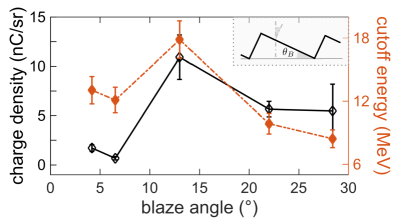
By studying a set of BGs as targets, a very strong enhancement of the bunch charge, up to pC per bunch, was found for a BG having a blaze angle of (Fig.2), optimized for m wavelength according to the above mentioned criterion. The same grating also yielded the highest cut-off energy of electrons amongst the tested BGs, although the enhancement was less dramatic with respect to that of the bunch charge.
It should be stressed that the investigation of BGs was limited to commercially available types and that so far no further optimization study or design of a specific BG has been completed. In addition, the available BGs had a metallic coatings which could favor the formation of a preplasma at the surface, affecting the interaction in an uncontrolled way. Nevertheless, the preliminary study of BGs reveal their potential for optimization of the SP coupling and secondary source performance, and is a further demonstration of the sensitivity of high-contrast femtosecond interaction to details of the surface structuring on a sub-micrometer scale.
IV High harmonic generation
IV.1 Experimental observation
In the interaction of short intense laser pulse with solid targets, high harmonics (HHs) of the laser frequency are emitted (see reviewsTeubner and Gibbon (2009); Thaury and Quéré (2010) and references therein). For the typical laser wavelength of m, the highest harmonic order may be high enough that the frequency reaches the extreme ultraviolet (XUV) range, and the coherence of the HHs results in a temporal structure of a train of attosecond pulses.
Whatever the details of the generation mechanism, from a flat surface the HHs are emitted in the specular direction, collinear to the reflected light at the first fundamental harmonic. Foreseen applications of the HHs may require their angular separation, which has been achieved using grating targetsYeung et al. (2011, 2013); Cerchez et al. (2013); Zhang et al. (2017) so that each HH is emitted at angles determined by the grating equation:
| (18) |
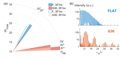
where is the diffraction order and is the angle of incidence. In our work we aimed to combine such angular separation with possible enhancement produced by SP excitation, when irradiating the grating at a resonant angle. PIC simulationsFedeli et al. (2017) performed to design the experiment showed that at the SP resonance both the highest value observed for and the associated intensity increased for HHs within angles compatible with those predicted by Eq.(18)), the enhancement being particularly strong for HHs emitted close to the tangent at the target surface.
While the preliminary PIC simulations were performed for a target with a step boundary profile, in the experiment a density profile with finite, sub-micron scalelength was produced by a controlled prepulseKahaly et al. (2013). As previously demonstrated in flat targets, such tailoring of the density profile leads to order-of-magnitude increase in the HH efficiency, and in the conditions of the experiment performed at SLIC this was essential for the detection of the signal. It is remarkable that the scalelength of the prepulse-produced density profile was of the same order of the grating depth, but the periodic structure was not destroyed since the effects of HH diffraction and enhancement at the SP resonance were evident and in line with the theoretical expectations.
The experimental observations are summarized in Fig.3. The HH spectrum emitted at an angle is compared with the spectrum of the HHs emitted from flat targets in the specular direction. The comparison shows an increase of the highest detectable order from in the flat case to in the grating case. At lower values of , the intensities of selected HHs are similar in the two cases, the spectrum from the grating being modulated as the result of the HH selection due to diffraction. Notice that the grating effects are stronger at an incidence angle of , slightly larger than the expected resonant value of . This is qualitatively consistent with the average density near the surface being lower than the solid value because of the preplasma production, so that the value of increases in accordance with Eqs.(1–2).
Electron emission near the tangent direction was simultaneously measured with the HH signal. The optimal conditions for HH enhancement did not correspond to the highest energy and strongest collimation for electronsCantono et al. (2018a), which was qualitatively in agreement with the dependence on the target density predicted by the simple model. However, the correlation between HH and electron emissions seems to play an important part in the HH generation mechanism supported by the SP, as indicated by the simulations discussed in the next section.
IV.2 Numerical simulation and generation mechanism
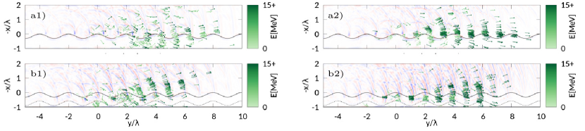
PIC simulations in 2D reproduced the experimental observations and gave an insight of the particular HH generation mechanism in the presence of a SP. In the simulations, the electron density was , the target thickness was , the laser pulse had a envelope and other target and laser parameters were the same as in the experiment (see Ref.Cantono et al., 2018a for details). Fig.4 shows snapshots from the simulations where some high energy electrons have been indicated by arrows parallel to their velocity. In order to evidentiate HH radiation on the same plot, the magnetic field (perpendicular to the plane of the simulations) is shown after filtering out its low harmonics components. The simulations are performed both without and with the preformed density gradient, the HH intensity being stronger in the latter case, in agreement with the experimental observations.
The HH pulses appear to be spatially correlated to the bunching of the high energy electrons in sub-wavelength structures, regularly spaced with a period close to the laser and SP wavelengths. More precisely, the HH pulses appear to propagate immediately ahead of the electron bunches. The scenario emerging from the simulations, in our current interpretation, is that electrons are accelerated by trapping in the SP potential wells, which also leads to bunching. The bunched electrons, being strongly relativistic, scatter the laser radiation preferentially along their velocity, resulting in collimated emission in a near-tangent direction.
In principle, XUV radiation in a direction close to that of the accelerated electrons could also be produced via the Smith-Purcell effectSmith and Purcell (1953). The wavelength observed at an angle from the target normal would be given by
| (19) |
where is the component of the electron velocity (normalized to parallel to the grating plane; we assume the diffraction order in the following estimates. By taking MeV electrons moving parallel to the grating and as in our set-up, Eq.(19) gives which falls outside both the range of our XUV spectrometer and the spatial resolution of our simulations. However, for strongly relativistic electrons and near-tangent radiation emission the result is strongly dependent upon the actual angle at which the electrons move with respect to the grating normal. In addition, both the energy and the angular spread of electrons would make the radiation broadband. Thus, while in principle Smith-Purcell radiation could contribute to the XUV emission, it cannot account for the harmonic structure observed in our experiments and simulations.111In Ref.Cantono et al., 2018b the inverse Smith-Purcell effectMizuno, Ono, and Shimoe (1975) was discussed and ruled out as a possible mechanism leading to electron acceleration along the grating.
V Concept for quasi-single-cycle plasmons
The most peculiar characteristic of the secondary sources of energetic radiation (including ions, electrons and photons) driven by short pulse lasers is their duration, which may open new possibilities in ultrafast science. For example, if the electron bunch duration can be shortened down to the few fs, or even sub-fs range (which obviously needs a monoenergetic spectrum to avoid velocity dispersion), electron diffraction becomes able to resolve atomic and molecular motionsZewail (2006); Sciaini and Miller (2011); Miller (2014). HH generation from solids can provide a source for applications in attosecond scienceHentschel et al. (2001); Baltuška et al. (2003); Agostini and DiMauro (2004); Cavalieri et al. (2007); Corkum and Krausz (2007); Krausz and Ivanov (2009) if a single as pulse can be isolated from other pulses in the train. A strategy for such aim is the use of a laser pulse with wavefront rotationQuéré et al. (2014) (WFR), which was shown to separate attosecond pulses in different directions (“lighthouse effect”).
We are currently investigating the effects of WFR in the context of SP excitation on gratings, in order to generate shorter SP-enhanced HH and electron emissions. The basic idea is that when a pulse with induced WFR is incident on a surface, the rotation of the phase front is equivalent to a continous rotation in time of the angle of incidence. Hence, when such pulse impinges on a grating near the resonant angle for SP excitation, the resonant condition is satisfied for a time shorter than the laser pulse duration and determined by the angular velocity of WFR. In other words, WFR may provide temporal gating of the SP resonance.
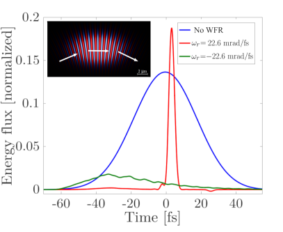
So far we have tested the concept in the linear regime, simulating the interaction of a WFR pulse with a metallic gratingPisani, Fedeli, and Macchi (2018) using the Meep FDTD codeOskooi et al. (2010). Fig.5 shows results obtained for a laser pulse of fs duration and m wavelength impinging on a grating at the resonant angle of . For a WFR angular velocity , i.e. 0.06 rad/cycle, the SP has a duration of 3.8 fs, which corresponds to 1.4 laser cycles. For such extreme durations, carrier-envelope or absolute phase effects become relevant in characterizing the temporal profile of the SP field.
As also apparent in Fig.5, the sign of is crucial to achieve the shortening effect. Based on our observations in the Meep simulations, we define the positive rotation as follows. Because of the WFR, each phase front impinges at a different angle on the target surface, which implies that the midpoint of each front (where the field amplitude has a maximum) slides along the surface. Thus, the centroid of the intensity distribution moves along the waist plane with a velocity that may be estimated as , the sign being dependent on that of . The value of increases when displacing the waist from the target plane, which can be used as an additional parameter to optimize the coupling. We found that must be in the same direction as the SP propagation velocity in order to achieve the shortening effect, which also comes with the peak amplitude of the few-cycle SP being higher than that of the “ordinary” SP excited without WFR. In the case of negative rotation, the excited SP is much weaker and not significantly shorter than the ordinary SP.
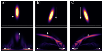
The effect of the sign of may be evidenced by comparing simulations in which the laser pulse impinges at normal incidence () on a grating with period . In this particular case, two oppositely propagating SPs are excited. Fig.6 shows that without WFR the two SPs are symmetrical. For positive (corresponding to the intensity contours of the laser pulse being inclined towards the right direction in Fig.6), the SP propagating from left to right is much shorter and stronger than the SP in the opposite direction. The situation is reversed for negative . The different amplitude of the plasmons can be also noticed in the different intensity of the field scattered by the plasmon (the parabolic tail structure in the bottom images of Fig.6) while propagates along the grating. Such scattering can be considered as the inverse effect of plasmon excitation by an EM wave impinging on a grating.
VI Conclusions and outlook
The experiments reviewed in this paper demonstrated that using high contrast femtosecond pulses it is possible to excite propagating surface plasmons on grating targets at relativistically strong intensities. These findings open up new possibilities for applications inspired by either “ordinary” (low field) plasmonics or high intensity laser-plasma physics. For example, the acceleration of electrons by surface plasmons can provide, with further optimization and characterization, a useful source of multi-MeV electrons for applications requiring high charge fluxes. The generation of high harmonic XUV pulses with sub-femtosecond duration and quasi collinear with the electron beam may also be of interest for pump-probe applications.
On this route to surface plasmon-based sources development and optimization, our most recent experiments have shown that it is possible to exploit the tailoring of the density profile on a sub-micrometer scale, either as pre-imposed (blazed gratings) or dynamically generated, i.e. optically induced “preplasmas”. The latter finding suggests that it may be even possible to exploit optical generation of the grating structuresMonchocé et al. (2014); Leblanc et al. (2017). Moreover, our proposed concept for the temporal gating of the surface plasmon resonance in order to generate single-cycle plasmons may find application in ultrafast plasmonics, also at low fields. On the high field side, developing the potential of relativistic surface plasmons will also benefit from a deeper theoretical understanding of their nonlinear behavior.
In conclusion, our investigations are a piece of work characterized by two words, femtosecond and nanometer, amongst the four words that “capture the essence of solid state plasmas and plasmonics” according to ManfrediManfredi (2018). As a general perspective, the control and exploitation of SPs on the nanoscale in space and femtoscale in time are at the frontier of plasmonics and strongly related to nonlinear effectsStockman (2011); Kauranen and Zayats (2012). While our results are just a very first step towards pushing the frontier towards the regime of superintense fields and sub-femtosecond duration, we expect that this extreme nanoplasmonics may further emerge as an active and promising research area across the traditional borders of plasmonics, attophysics, and relativistic plasma physics.
Acknowledgements.
We are grateful to C. Riconda and A. Sgattoni for their longstanding collaboration on the topic of high field plasmonics, and to F. Amiranoff for enlightening discussions. We also acknowledge the contributions of L. Chopineau, A. Denoeud, D. Garzella, F. Reau, I. Prencipe, M. Passoni, M. Raynaud, M. Květoň, and J. Proska to the research reviewed in this paper, the help by J.-P. Larbre (ELYSE, Université Paris Sud, Orsay, France) in the calibration of the Lanex screen, and the overall support of the Saclay Laser Interaction Center team. Simulations were performed using the PICcante code at the HPC Cluster CNAF (Bologna, Italy), with the precious help of S. Sinigardi. This research received financial support from LASERLAB-EUROPE (Grant agreement No. 284464, EU FP7), Investissement d’Avenir LabEx PALM (Grant ANR-10-LABX-0039), Triangle de la physique (Contract No. 2014-0601T), and Agence Nationale pour la Recherche (Grant No.ANR-14-CE32-0011). G. C. acknowledges partial support by the Université Franco-Italienne (Vinci program 2015, Grant No. C2-92). L. F. acknowledges partial support by the European Research Council Consolidator Grant ENSURE (ERC-2014-CoG No. 647554).References
- Manfredi (2018) G. Manfredi, Phys. Plasmas 25, 031701 (2018).
- Gauthier et al. (1995) J.-C. Gauthier, S. Bastiani, P. Audebert, J.-P. Geindre, K. Neuman, T. D. Donnelly, M. Hoffer, R. W. Falcone, R. L. Shepherd, D. F. Price, and W. E. White, Proc. SPIE 2523, 242 (1995).
- Strickland and Mourou (1985) D. Strickland and G. Mourou, Optics Comm. 55, 447 (1985).
- Kahaly et al. (2008) S. Kahaly, S. K. Yadav, W. M. Wang, S. Sengupta, Z. M. Sheng, A. Das, P. K. Kaw, and G. R. Kumar, Phys. Rev. Lett. 101, 145001 (2008).
- Hu et al. (2010) G. Hu, A. Lei, W. Wang, X. Wang, L. Huang, J. Wang, Y. Xu, J. Liu, W. Yu, B. Shen, R. Li, and Z. Xu, Phys. Plasmas 17, 033109 (2010).
- Bagchi et al. (2012) S. Bagchi, P. P. Kiran, W.-M. Wang, Z. M. Sheng, M. K. Bhuyan, M. Krishnamurthy, and G. R. Kumar, Phys. Plasmas 19, 030703 (2012).
- Kapteyn et al. (1991) H. C. Kapteyn, M. M. Murnane, A. Szoke, and R. W. Falcone, Opt. Lett. 16, 490 (1991).
- Dromey et al. (2004) B. Dromey, S. Kar, M. Zepf, and P. Foster, Rev. Sci. Instrum. 75, 645 (2004).
- Lévy et al. (2007) A. Lévy, T. Ceccotti, P. D’Oliveira, F. Réau, M. Perdrix, F. Quéré, P. Monot, M. Bougeard, H. Lagadec, P. Martin, J.-P. Geindre, and P. Audebert, Opt. Lett. 32, 310 (2007).
- Thaury et al. (2007) C. Thaury, F. Quere, J.-P. Geindre, A. Levy, T. Ceccotti, P. Monot, M. Bougeard, F. Reau, P. d’Oliveira, P. Audebert, R. Marjoribanks, and P. Martin, Nature Phys. 3, 424 (2007).
- Macchi (2018) A. Macchi, Phys. Plasmas 25, 031906 (2018).
- Ceccotti et al. (2013) T. Ceccotti, V. Floquet, A. Sgattoni, A. Bigongiari, O. Klimo, M. Raynaud, C. Riconda, A. Heron, F. Baffigi, L. Labate, L. A. Gizzi, L. Vassura, J. Fuchs, M. Passoni, M. Květon, F. Novotny, M. Possolt, J. Prokůpek, J. Proška, J. Pšikal, L. Štolcová, A. Velyhan, M. Bougeard, P. D’Oliveira, O. Tcherbakoff, F. Réau, P. Martin, and A. Macchi, Phys. Rev. Lett. 111, 185001 (2013).
- Fedeli et al. (2016) L. Fedeli, A. Sgattoni, G. Cantono, D. Garzella, F. Réau, I. Prencipe, M. Passoni, M. Raynaud, M. Květoň, J. Proska, A. Macchi, and T. Ceccotti, Phys. Rev. Lett. 116, 015001 (2016).
- Cantono et al. (2018a) G. Cantono, L. Fedeli, A. Sgattoni, A. Denoeud, L. Chopineau, F. Réau, T. Ceccotti, and A. Macchi, Phys. Rev. Lett. 120, 264803 (2018a).
- Cantono et al. (2018b) G. Cantono, A. Sgattoni, L. Fedeli, D. Garzella, F. Réau, C. Riconda, A. Macchi, and T. Ceccotti, Phys. Plasmas 25, 031907 (2018b).
- Pellegrini, Marinelli, and Reiche (2016) C. Pellegrini, A. Marinelli, and S. Reiche, Rev. Mod. Phys. 88, 015006 (2016).
- Wheeler et al. (2012) J. A. Wheeler, A. Borot, S. Monchocé, H. Vincenti, A. Ricci, A. Malvache, R. Lopez-Martens, and F. Quéré, Nature Photonics 6, 829 (2012).
- Vincenti and Quéré (2012) H. Vincenti and F. Quéré, Phys. Rev. Lett. 108, 113904 (2012).
- Pisani, Fedeli, and Macchi (2018) F. Pisani, L. Fedeli, and A. Macchi, ACS Photonics 5, 1068 (2018).
- Quéré et al. (2014) F. Quéré, H. Vincenti, A. Borot, S. Monchocé, T. J. Hammond, K. T. Kim, J. A. Wheeler, C. Zhang, T. Ruchon, T. Auguste, J. F. Hergott, D. M. Villeneuve, P. B. Corkum, and R. Lopez-Martens, J. Phys. B: At. Mol. Opt. Phys. 47, 124004 (2014).
- MacDonald et al. (2009) K. F. MacDonald, Z. L. Sámson, M. I. Stockman, and N. I. Zheludev, Nature Photonics 3, 55 (2009).
- Dombi et al. (2010) P. Dombi, S. E. Irvine, P. Rácz, M. Lenner, N. Kroó, G. Farkas, A. Mitrofanov, A. Baltuška, T. Fuji, F. Krausz, and A. Y. Elezzabi, Opt. Express 18, 24206 (2010).
- Krüger, Schenk, and Hommelhoff (2011) M. Krüger, M. Schenk, and P. Hommelhoff, Nature 475, 78 (2011).
- Rácz et al. (2011) P. Rácz, S. Irvine, M. Lenner, A. Mitrofanov, A. Baltuška, A. Elezzabi, and P. Dombi, Appl. Phys. Lett. 98, 111116 (2011).
- Li et al. (2013) R. Li, H. To, G. Andonian, J. Feng, A. Polyakov, C. Scoby, K. Thompson, W. Wan, H. Padmore, and P. Musumeci, Phys. Rev. Lett. 110, 074801 (2013).
- Polyakov et al. (2013) A. Polyakov, C. Senft, K. Thompson, J. Feng, S. Cabrini, P. Schuck, H. Padmore, S. J. Peppernick, and W. P. Hess, Phys. Rev. Lett. 110, 076802 (2013).
- Sgattoni et al. (2016) A. Sgattoni, L. Fedeli, G. Cantono, T. Ceccotti, and A. Macchi, Plasma Phys. Contr. Fusion 58, 014004 (2016).
- Maier (2007) S. A. Maier, Plasmonics: fundamentals and applications (Springer Science & Business Media, 2007).
- Tsang, Srinivasan-Rao, and Fischer (1991) T. Tsang, T. Srinivasan-Rao, and J. Fischer, Phys. Rev. B 43, 8870 (1991).
- Dombi and Rácz (2008) P. Dombi and P. Rácz, Opt. Express 16, 2887 (2008).
- Hwang, Vorobyev, and Guo (2009) T. Y. Hwang, A. Y. Vorobyev, and C. Guo, Phys. Rev. B 79, 085425 (2009).
- Watanabe, Inami, and Kawata (2011) Y. Watanabe, W. Inami, and Y. Kawata, Journal of Applied Physics 109, 023112 (2011).
- Gong et al. (2014) Y. Gong, A. G. Joly, L. M. Kong, P. Z. El-Khoury, and W. P. Hess, Phys. Rev. Applied 2, 064012 (2014).
- Ono et al. (2015) A. Ono, N. Shiroshita, M. Kikawada, W. Inami, and Y. Kawata, Journal of Physics D: Applied Physics 48, 184005 (2015).
- Zawadzka et al. (2001) J. Zawadzka, D. A. Jaroszynski, J. J. Carey, and K. Wynne, Applied Physics Letters 79, 2130 (2001).
- Kupersztych, Monchicourt, and Raynaud (2001) J. Kupersztych, P. Monchicourt, and M. Raynaud, Phys. Rev. Lett. 86, 5180 (2001).
- Kupersztych, Raynaud, and Riconda (2004) J. Kupersztych, M. Raynaud, and C. Riconda, Phys. Plasmas 11, 1669 (2004).
- Irvine, Dechant, and Elezzabi (2004) S. E. Irvine, A. Dechant, and A. Y. Elezzabi, Phys. Rev. Lett. 93, 184801 (2004).
- Irvine and Elezzabi (2006) S. E. Irvine and A. Y. Elezzabi, Phys. Rev. A 73, 013815 (2006).
- Tajima and Dawson (1979) T. Tajima and J. M. Dawson, Phys. Rev. Lett. 43, 267 (1979).
- Riconda et al. (2015) C. Riconda, M. Raynaud, T. Vialis, and M. Grech, Phys. Plasmas 22, 073103 (2015).
- Yeung et al. (2013) M. Yeung, B. Dromey, C. Rödel, J. Bierbach, M. Wünsche, G. Paulus, T. Hahn, D. Hemmers, C. Stelzmann, G. Pretzler, and M. Zepf, New J. Phys. 15, 025042 (2013).
- Zhang et al. (2017) G. Zhang, M. Chen, F. Liu, X. Yuan, S. Weng, J. Zheng, Y. Ma, F. Shao, Z. Sheng, and J. Zhang, Opt. Express 25, 23567 (2017).
- Teubner and Gibbon (2009) U. Teubner and P. Gibbon, Rev. Mod. Phys. 81, 445 (2009).
- Thaury and Quéré (2010) C. Thaury and F. Quéré, J. Phys. B: At. Mol. Opt. Phys. 43, 213001 (2010).
- Yeung et al. (2011) M. Yeung, M. Zepf, M. Geissler, and B. Dromey, Opt. Lett. 36, 2333 (2011).
- Cerchez et al. (2013) M. Cerchez, A. L. Giesecke, C. Peth, M. Toncian, B. Albertazzi, J. Fuchs, O. Willi, and T. Toncian, Phys. Rev. Lett. 110, 065003 (2013).
- Fedeli et al. (2017) L. Fedeli, A. Sgattoni, G. Cantono, and A. Macchi, Appl. Phys. Lett. 110, 051103 (2017).
- Kahaly et al. (2013) S. Kahaly, S. Monchocé, H. Vincenti, T. Dzelzainis, B. Dromey, M. Zepf, P. Martin, and F. Quéré, Phys. Rev. Lett. 110, 175001 (2013).
- Smith and Purcell (1953) S. J. Smith and E. M. Purcell, Phys. Rev. 92, 1069 (1953).
- Note (1) In Ref.\rev@citealpnumcantonoPoP18 the inverse Smith-Purcell effectMizuno, Ono, and Shimoe (1975) was discussed and ruled out as a possible mechanism leading to electron acceleration along the grating.
- Zewail (2006) A. H. Zewail, Annual Review of Physical Chemistry 57, 65 (2006).
- Sciaini and Miller (2011) G. Sciaini and R. J. D. Miller, Rep. Prog. Phys. 74, 096101 (2011).
- Miller (2014) R. J. D. Miller, Science 343, 1108 (2014).
- Hentschel et al. (2001) M. Hentschel, R. Kienberger, C. Spielmann, G. A. Reider, N. Milosevic, T. Brabec, P. Corkum, U. Heinzmann, M. Drescher, and F. Krausz, Nature 414, 509 (2001).
- Baltuška et al. (2003) A. Baltuška, T. Udem, M. Uiberacker, M. Hentschel, E. Goulielmakis, C. Gohle, R. Holzwarth, V. S. Yakovlev, A. Scrinzi, T. W. Hänsch, and F. Krausz, Nature 421, 611 (2003).
- Agostini and DiMauro (2004) P. Agostini and L. F. DiMauro, Rep. Prog. Phys. 67, 813 (2004).
- Cavalieri et al. (2007) A. L. Cavalieri, N. Müller, T. Uphues, V. S. Yakovlev, A. Baltuška, B. Horvath, B. Schmidt, L. Blümel, R. Holzwarth, S. Hendel, M. Drescher, U. Kleineberg, P. M. Echenique, R. Kienberger, F. Krausz, and U. Heinzmann, Nature 449, 1029 (2007).
- Corkum and Krausz (2007) P. B. Corkum and F. Krausz, Nature Physics 3, 381 (2007).
- Krausz and Ivanov (2009) F. Krausz and M. Ivanov, Rev. Mod. Phys. 81, 163 (2009).
- Oskooi et al. (2010) A. F. Oskooi, D. Roundy, M. Ibanescu, P. Bermel, J. Joannopoulos, and S. G. Johnson, Comp. Phys. Comm. 181, 687 (2010).
- Monchocé et al. (2014) S. Monchocé, S. Kahaly, A. Leblanc, L. Videau, P. Combis, F. Réau, D. Garzella, P. D’Oliveira, P. Martin, and F. Quéré, Phys. Rev. Lett. 112, 145008 (2014).
- Leblanc et al. (2017) A. Leblanc, A. Denoeud, L. Chopineau, G. Mennerat, P. Martin, and F. Quéré, Nature Physics 13, 440 (2017).
- Stockman (2011) M. I. Stockman, Opt. Express 19, 22029 (2011).
- Kauranen and Zayats (2012) M. Kauranen and A. V. Zayats, Nature Photonics 6, 737 (2012).
- Mizuno, Ono, and Shimoe (1975) K. Mizuno, S. Ono, and O. Shimoe, Nature 253, 184 (1975).