iint \restoresymbolTXFiint
A Formal Verification Technique for Architecture-based Embedded Systems in EAST-ADL
Abstract
Development of quality assured software-intensive systems, such as automotive embedded systems, is an increasing challenge as the complexity of these systems significantly increases. EAST-ADL is an architecture description language developed to specify automotive embedded system architectures at multiple abstraction levels in the development of safety-critical automotive products. In this paper, we propose an architecture-based verification technique which enhances the model-based development process supported by EAST-ADL by adapting model-checking to EAST-ADL specifications. We employ UPPAAL as a verification tool to ensure that predicted function behaviors of the models in EAST-ADL satisfy functional and real-time requirements. The criteria for this architecture-based verification is presented and the transformation rules which comply with this criteria are derived. This enables us to extract the relevant information from EAST-ADL specifications and to generate analyzable UPPAAL models. The formal semantics of EAST-ADL is defined which is essential to automate the verification of EAST-ADL specifications. Our approach is demonstrated by verifying the safety of the steering truck system units.
1 Introduction
EAST-ADL is an architecture description language for the development of automotive embedded systems [1]. Advanced automotive functions [2, 3] are increasingly dependent on software and electronics. These automotive embedded systems are becoming progressively complex and critical for the entire vehicle. Among such factors which effect the complexity are an increasing number of components and interactions between them as well as inter-disciplinary communication. Model-based development (MBD) – i.e., the use of computerized models [4] supports activities or tools performing activities such as architecture specification, analysis, V&V, testing and synthesis – is a means to manage this complexity and develop embedded systems in a way that increases safety and quality.
The EAST-ADL modeling approach addresses this issue and provides the means to integrate engineering information from documents, spreadsheets and legacy tools into one systematic structure, an EAST-ADL system model. Its methodology [5] is an emerging MBD solution for automotive embedded systems development, providing support for architecture specification and constraints at multiple abstraction levels. EAST-ADL expresses the structure and interconnection of the system. System behavior is defined based on the definition of a set of elementary functional entities and their triggers and interfaces. However, the behavioral semantics inside each elementary functional entity is not specified, which limits the automatic translation from EAST-ADL models to other formal models for efficient verification. Instead, the execution of each function is described with external informal notations [6] and a legacy tool such as Simulink [7], which is deficient in the analysis of timing requirements with high-level assurance.
In order to alleviate the aforementioned restriction, we aim to bring in modeling formalisms to the behavioral definitions of EAST-ADL that enhances the specification and analysis support for system models in EAST-ADL, especially early V&V of behavioral specifications, taking into account time- and behavioral constraints. We propose an architecture-based verification technique, which is based on formal constructs enabling automation of the verification activities by adopting model checking to an architectural perspective: We first introduce an EAST-ADL based verification criteria which describes – 1. the objects of verification, i.e., constructs of EAST-ADL selected for evaluation, and – 2. the conditions these objects have to meet. Furthermore, the formal semantics of EAST-ADL is defined and it is critical to automate verification of EAST-ADL specifications. Secondly, we present semantics mapping rules which comply with this criteria in order to transform the selected constructs of EAST-ADL into UPPAAL Timed Automata (TA) models [8, 9]. Finally, we demonstrate the applicability of model checking in automotive applications.
This work is organized as follows. Section 2 introduces technology and background, EAST-ADL and UPPAAL toolkit as used in our approach. Section 3 presents our approach and methodology to improve formal analysis and verification capability of EAST-ADL. In section 4, our method is demonstrated in verifying the safety of the steering system units design. In section 5, related work is discussed. Section 6 concludes the paper and plans future work.
2 Preliminaries
2.1 EAST-ADL
EAST-ADL (Electronics, Architecture and Software Technology – Architecture Description Language) is an ADL dedicated to automotive electronic systems resulting from several European projects [10, 1]. The language provides support for architectural specifications at different abstraction levels.
The highest abstraction level, Vehicle(Feature) level, characterizes a vehicle by means of its features and requirements. At Analysis level, functionality is realized based on the features and requirements. These features and requirements are refined by the decision of logical design with the definition of logical abstract functions of features and their interactions, and requirements. The model at this level is used for the analysis of control requirements, timing constraints, data consistency between interfaces, hazard identification, etc. Design level contains concrete functional definitions according to the realized logical design. In particular, functional definitions of application software, functional abstraction of hardware and middleware are presented, as well as hardware architecture being captured and function-to-hardware allocation being defined. At Implementation level, the component architecture is represented using the AUTOSAR standard [11] or similar specifications.
EAST-ADL has extensions for environment modeling, requirements specification, timing, dependability and V V at every abstraction level. This modular approach separates the definition of functional and non-functional aspects such as behavior and related constraints for such behaviors as timing, and safety. The behavior annex [6] contains extensions to EAST-ADL for a more fine-grained specification of key behavior attributes and is aligned with the language but not yet validated, nor included in the base specification.
In this paper we refer to this behavioral annex (BA) to construct an analyzable UPPAAL TA model. The contents of BA such as timing- and behavior constraints, are utilized to constrain behavioral definitions in the UPPAAL TA model. Moreover, those constraints as well as textual requirements are formalized in linear time logics and are used as UPPAAL queries, which can be verified over the generated TA model by UPPAAL model checker. Details will be explained in Section 3.
2.2 UPPAAL
UPPAAL [8] is a model checking tool for modeling, validation and verification of real-time systems. UPPAAL is used to model a system as a network of Timed Automata (TA)[9] – this tool allows construction of large models by composing TA in parallel and permits communications between TAs using share discrete and clock variables and synchronize (rendezvous-style) on complementary input and output actions, as well as broadcast actions – and to verify requirements of the model by the UPPAAL query language expressed in a subset of Computational Tree Logic (CTL) [12]. The property specification language supports safety, liveness, deadlock, and response properties that can be solved by reachability analysis.
UPPAAL is comprised of three main parts: an editor, a simulator, and a verifier for modeling, early fault detection (by examination without exhaustive checking) and verification (covering exhaustive dynamic behavior) respectively in a graphical environment. UPPAAL uses the concept of templates for reusability and prototyping of system components. Each template can be instantiated multiple times to represent similar TA with varying parameters.
Additional features offered by UPPAAL in comparison to other model-checking tools are bounded integer variables, committed and urgent conditions. Committed locations must be left immediately by the next transition taken in the system. Urgent locations must be left without letting time pass, but allows interleaving by other automata. For details of UPPAAL TA, we refer the reader to [8].
Another feature of UPPAAL is the use of a subset of C-code for its declarations. This is beneficial in the sense that C is one of the most commonly used languages for real-time systems. Furthermore, it is possible to use C syntax for EAST-ADL expressions. L.Feng et al. [13] transformed C syntax in EAST-ADL to PROMELA to enable model checking in SPIN. This is not required in the case of UPPAAL if the same subset of C is used for both EAST-ADL and UPPAAL.
3 Approach and Methodology
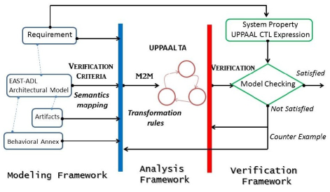
To achieve our aforementioned goal in section 1, we propose a formal approach which facilitates the verification of system behaviors in EAST-ADL by using UPPAAL model-checker independently of any hardware constraints and topology mapping. It focuses mainly on the higher level of functional behavior of applications at Analysis level in terms of its Feature level with three distinct phases – verification criteria, M2M transformation, and verification (model checking). We will discuss those phases in more detail in following sections.
3.1 Verification Criteria
An EAST-ADL-based verification criteria is introduced and applied to the step from Modeling Framework to Analysis Framework in our methodology roadmap Fig.1. Indeed, the formal semantics of EAST-ADL is defined and it is essential to facilitate the automation of V&V technique.
The verification criteria describes the objects of verification, i.e., constructs of EAST-ADL specifications selected for evaluation, and the conditions these objects have to meet. The possible objects are restricted to four different types of constructs: Functions, Ports and Connectors, Artifacts, and Behavioral Annex.
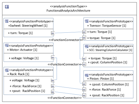
Functions: EAST-ADL refers to components as features, functions or components, depending on which conceptual abstraction level is considered. As we focus on Analysis level, AnalysisFunctions (AF) are selected as abstraction of computational units, i.e. SteeringColumnCalculator, TorqueSensor, etc. They are illustrated as function entities in Fig.2. Each AF has its own logical execution, which is specified in UPPAAL TA and used for verification in this paper.
Ports and connectors: There are two types of function interaction either a FunctionFlowPort interaction whereby a function performs a computation on provided data, or a ClientServerPort interaction whereby the execution of a service is called upon by another function. The FunctionFlowPort are directional interaction points for exchange of data between AFs and specified by associated data-types, and they are connected to other ports via connectors. Both interactions are validated by checking if the execution of TA and its synchronization with other TAs are not blocked. Since EAST-ADL connectors are dependent on the ports of AFs they connect, the modeling and verifying connectors should describe which AF ports are connected together, and ensure that data- and control flows interactions between AFs through the ports are correct respectively.
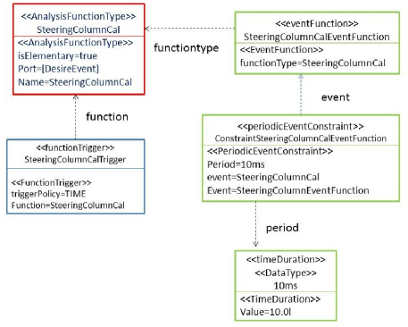
Artifacts: Each AF consists of three different kinds of artifacts: structure, behavior and timing packages. They are shown as red, blue, and green respectively in Fig.3 where the FunctionTrigger defines TriggerPolicy as either time or event-behavior to specify timing constraints. According to the TriggerPolicy, the AF is invoked either by time-triggered in which time alone causes execution to start, or event-triggered, which is caused by data arrival or calls on the input ports. For each AF, its artifacts are used to construct corresponding TA and declare how the execution of TA is dispatched.
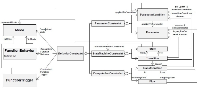
Behavioral Annex (BA): BA contains behavioral constraints which are given in three categories: Parameter Constraints, State Machine Constraints, and Computation Constraints (See Fig.4 with dependencies). Based on aforementioned artifacts, we further detail each computation and execution behavior of TA by capturing related Parameter-, State Machine-, and Computation Constraints from BA.
In reference to Parameter Constraints, we specify – 1. quantities of constraints to be processed by the computation and execution behavior of TA model, and – 2. conditions under which each of these quantities is used. The conditions of Parameter Constraints such as pre-, post, and invariant conditions in the computational modes in EAST-ADL as well as the relations of parameters (e.g., input and output mapping, event to output mapping) are used as (i.e. translated into) the corresponding conditions in TA model. The locations and transitions of TA model are constructed taking into account State Machine Constraints. The logical transformation of data in a FunctionalBehavior is represented in TA by referring to Computation Constraints or the conditions of Parameter Constraints
According to the objects of verification above, the execution of FunctionalBehavior within an EAST-ADL system can be considered a combination of multiple end-to-end computation and execution chains across its AFs under the triggering definitions, and the behavioral- and timing constraints given in artifacts and BA respectively. Thus, evaluating the FunctionalBehavior in EAST-ADL is to ensure the two following conditions:
-
1.
For each AF, its corresponding TA execution such as flow- or data interaction via synchronization with its environments (other TAs) is not blocked, i.e., Deadlock-free condition.
-
2.
When the interaction or synchronization is carried out, data transformation is performed as an expected computation activity on two sets of parameters. The conditions of those parameters such as pre-, post-, and invariant conditions must hold before the transformation starts its execution, after the execution of the transformation, and must remain unchanged by the execution of the transformation respectively.
To perform a behavioral semantics mapping from the informal semantics of EAST-ADL architectural model to the formal semantics of UPPAAL TA model, we formally define behavioral semantics of EAST-ADL below. This step is critical to automate the verification technique using UPPAAL model checker. UPPAAL tool composes each local TA of AF in parallel to a composed TA (network TA).
Essentially, EAST-ADL model is a tuple , where is a set of ADLFunctionalPrototypes AFs, and is the set of connectors between AFs. Output variables of one AF may be connected to input variables of another AF. The behavior inside an AF, noted , is modeled as an UPPAAL TA , where is a set of locations, is the initial location, and is a set of clock and data variables respectively. assigns an invariant to each of the locations. is a set of edges, represented as , where is a source location, is a destination location, is a guard, is an action, is an update.
The execution of each AF behavior is determined in terms of triggering values (conditions) given in BA or artifacts. When the triggering condition is active, the AF is triggered via its input trigger port, and its input data ports are mapped to data variables. in TA are updated with those variables by read-input-from-ports action, noted READ(), (respectively write-output-to-ports, noted WRITE()), which are atomic and urgent (in the sense that time is not allowed to pass when AF reads or writes). AF is initially idle after the read action it switches to its executing locations until its internal computation is done. After the write action, which forwards data in variables via connections from the output ports, the AF becomes idle again and the trigger condition is updated to inactive. The behavior of AF is formally defined as follows:
-
Definition 1
The behavior of AnalysisFunction AF is a tuple where
-
–
is the initial location (also considered the idle location).
-
–
is the final executable location such that the edges in leading out from lead to the .
-
–
is the set of ports of the component described as , where is a set of input ports, is a set of output ports, is the set of trigger input ports.
-
–
, if is triggered, is the ”read-input-from-ports” action, READ(), and updates with input values .
-
–
, if is true, is the ”write-outputs-on-ports” action, WRITE(), and resets to ”inactive”.
-
–
The TA of a composition , TA(), is defined as a network of local TA. For and its corresponding component , the write action in TA() is extended to update the input ports (noted ) of a target component according to interconnections from the out ports of (noted ). An interconnection connects a source port to a target port whenever variables in of are enabled in a way that if is a trigger port then is activated, otherwise . The edges of TA() are explained with extended write actions as follows.
-
Definition 2
The behavior inside , , is TA() , , , , such that
-
–
() ( ; ()), if and is triggered (holds).
Note that ; is defined as sequential execution -
–
() , for
The automata TA(C) is then the network of each TA() for .
-
–
An environment is modeled as in a similar way. The resulting composition is thus defined as the network , where any edge in updating ports of , is extended with an update . This is similar to the adaption of the action that is used to build in Definition 2.
3.2 M2M Transformation
This model-to-model transformation step, called M2M, is to transform EAST-ADL specifications to UPPAAL models under the verification criteria. This step is illustrated as a M2M direction in Analysis Framework in Fig.1. Automated formal verification is not feasible directly on EAST-ADL specification since EAST-ADL lacks formal and implemented semantics. In order to perform automated formal verification, we first formally mapped the execution semantics of EAST-ADL to UPPAAL TAs (Ref. Def 1 and 2 in Section 3.1).
In this section, we present transformation rules which helps to extract executable UPPAAL TAs from EAST-ADL specifications. The derived UPPAAL models comply with artifact packages, BA and functional requirements of EAST-ADL model under the verification criteria. A few assumptions are made in order to simplify the transformation procedure:
-
•
We focus on FunctionalAnalysisArchitecture (FAA) at the analysis level of EAST-ADL where each AF is associated with AnalysisPorts. Except for FAA, no function type is allowed to have instances for other function types.
-
•
Unlike the original EAST-ADL specification, ports’ events are related not only to triggering but also to synchronization. This implies that sending and receiving data from a port is also considered an event although it is not used to trigger a particular function. This assumption is required for the verification of end-to-end timing property using reaction time constraints.
-
•
The communication channels between different processes in UPPAAL is of broadcast type. This complies with EAST-ADL specifications where each elementary AF follows run-to-completion execution with non-blocking semantics and ports are over-writable buffers.
In terms of these assumptions, we first present a general transformation scheme which can be described as follows.
M2M General Transformation Scheme: For each EAST-ADL system (FAA), an UPPAAL system consisting of a set of processes is created. For each elementary AF, an UPPAAL process is defined whereby a local clock is declared. This local clock is used to specify the execution time of AF.
Each connector between AF ports is transformed to an UPPAAL broadcast channel. Global and local variables of processes are defined regarding Parameter Constraints in BA. The value-passing action between two AFs is performed using global variables via broadcasting channels between the corresponding UPPAAL processes. Control- or data flow behaviors of AFs follow the computation activities on two sets of quantities in terms of the Computation- and StateMachine constraint, i.e., pre-, port-, and invariant parameter conditions in BA.
Secondly, and more importantly, we present three transformation rules, Time-Triggering rule, Event-Triggering rule, and End-to-End reaction time rule. Each proposed transformation rule is specified in UPPAAL TA and a schematic graphical-structure view of the corresponding EAST-ADL is illustrated below.
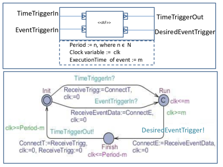
Time-Triggering rule: This rule transforms the periodic behaviors of AF. From the given artifacts and BA of EAST-ADL model, if related FunctionTriggerPolicy is TIME and its TriggerPeriod defines the periodic triggering time , i.e., this AF is invoked every time, then the EAST-ADL model which is illustrated as the upper view in Fig.5 is transformed to the corresponding TA which is depicted as the lower view in Fig.6.
An event-triggered function may be invoked during the time-triggering period due to data arrival or call from or to other AFs. If this happens, then an invariant ( is of the event) is added to location. An invariant in Finish location specifies the expiry of the fixed-periodic triggering time after the of event-triggered functions. For each transition, the local clock is reset. For each port associated with its connector, a related broadcast channel is defined as the port name and representing time-triggering input- and output ports or and representing event-triggering input- and output ports respectively.
A global integer variable and a local integer variable are declared. is assigned the value of 1 initially. When a time-triggering signal is received through , the local variable is assigned the value of . When the signal is sent out through , the global variable is assigned the value of , and then the local variable is reset to 0.
Similarly, the value of is passed from the current TA in Fig.5 to the variable of TA in Fig.6 using the global variable through the broadcast channel . Location in Fig.5 is committed to ensure that no other TAs can assign their local variables with the value of before the TA in Fig.6 sets . Once the periodic triggering time is expired, i.e., , then is broadcast. Therefore, this rule can facilitate the synchronization of various clocks in a design and avoid unpredictable delays.
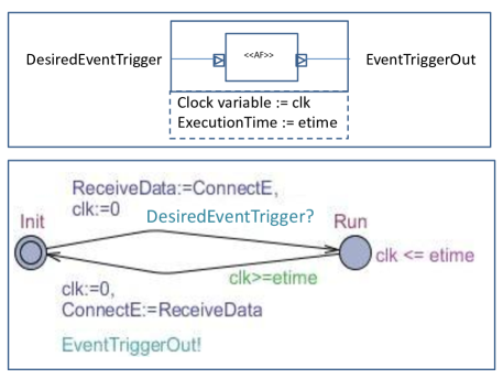
Event-Triggering rule: From the given artifacts and BA of EAST-ADL model, for any AF if related FunctionTriggerPolicy is EVENT and its TriggerPeriod defines the execution time of the invoked event , then the EAST-ADL model which is illustrated as the upper view in Fig.6 is transformed to the corresponding TA, which is depicted as the lower view. The defined execution time () is added as an invariant to location to specify the expiry of the of event-triggering function. For each transition, the local clock is reset. For each port, a relevant broadcast channel is defined as the port name and representing event-triggering input- and output ports respectively. Value passing from current TA to the others is represented similar to the aforementioned one in the Time-triggering rule above.
The executable event flows from location to location can be refined into corresponding behavioral automaton where and locations being the initial location and the final location respectively. The refinement is made straightforward by adding more locations, transitions, and associated variables as well as broadcasting channels between and locations. They represent more interactions between the current AF and other AFs. The timing properties of the basic and refined model should be identical, because the newly introduced locations represent the former original location, and the union of the new locations clock invariants (union of individual execution time) should fulfill the former invariant execution time ().
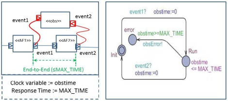
End-To-End reaction time rule: This rule transforms the End-To-End reaction time behavior between two AFs into TAs. The reaction time constraint which is given in BA is first represented as the bounded response time property formula of the form , meaning that if a request (f1) becomes true at a certain time point, a response (f2) must be guaranteed to be true within a time bound (T).
In order to verify this time constraint property, we take a similar approach from our early experiment in [14], which shows how to check bounded liveness properties with a certain syntactical manipulation on the system model. An observer TA (see righthand view in Fig.7), which restricts the bounded response time () is constructed. This observer TA contains a clock constraint () and an error location, which violates the bounded response time condition.
One synchronization channel is added to the transition from to in order to deal with a request event of AF1. Another synchronization channel is added to the transition from to in order to handle a response event of AF2. Afterwards, the observer is syntactically composed with the actual AFs (TAs), say AF1 (TA1) and AF2 (TA2), then we checked if its error location can never be reached from any location of AF1 (TA1) and AF2 (TA2).
3.3 Verification: Model Checking
The execution of each FunctionBehavior in EAST-ADL is transformed to UPPAAL TA which holds the verification criteria and its composition is considered as the network TA. The formal semantics of EAST-ADL has been investigated, where UPPAAL TA is used. The entire system (network TA) is considered in terms of a timed transition system, then this entire system is verified by UPPAAL model-checker. Quality requirements (e.g, timing, safety, deadlock freedom) in terms of functional requirements (e.g, behavioral constraints, timing constraints), see Fig.1-Requirement aspect, are formalized in linear time logics based on the UPPAAL logic, which can be verified over the transformed TA model by UPPAAL model checker. This step is shown as Verification Framework in Fig.1.
In particular, the quality requirements are derived from a given system’s textual descriptions. One may verify certain delay, reaction and synchronization constraints (i.e, overall behavioral constraints of a system) according to the quality requirements. For example, a plausible reaction constraint is 250 ms. In contrast, functional requirements describe particular constraints of a function such as timing constraints and trigger elements linked to an AF entity, i.e., triggering policy and parameter constraints in artifacts and BA.
UPPAAL model checker verifies those two types of requirements as safety properties in a way that (1). if a property is satisfied by the target model, then a functional requirement linked to an AF is updated to a satisfy relation and generic constraints of the AF are stored as valid invariants in the VV structure (VVOutcome linked to the explained requirement, VVCase, etc) of the EAST-ADL model. (2). If a property is violated (depicted as Not Satisfied arrows in Fig.1) then UPPAAL model checker returns some counterexamples that can help analysts to refine the behavioral constraints of the system model or modify generic constraints in BA, and identify correct constraints for the AF that it concerns. Thus, the models in EAST-ADL are updated with the timing assumptions analysts make as well as the analysis results.
4 Experiment
Our approach applied and demonstrated on a case study, the Steering System Units (SSU), from our industrial partner VOLVO. It is first modeled using Papyrus UML [15] for EAST-ADL in the ATESST2 project [1]. The SSU Papyrus UML model consists of six AFs and the interfaces of the AFs are expressed in terms of ports and connections as depicted in Fig.2. Each of these AFs can be further decomposed into smaller or more detail DesignFunctions or Components depending on the level of abstraction in EAST-ADL. The functionalities (AFs) of SSU used within the current work are as follows:
-
•
Steering Wheel is manipulated by the driver and reads such driver input;
-
•
Torque Sensor senses the steering wheel position and sends a desired torque to the steering column calculator;
-
•
Steering Column Calculator calculates the torque and positions required for the pinion and sends the calculated values to the pinion;
-
•
Pinion senses a rotational motion in terms of the calculated values from the steering column calculator and sends a desired torque force as well as a desired rack command to the rack;
-
•
Rack converts a rotational motion into a linear motion based on the received values and commands from the pinion;
-
•
Actuator performs the actual steering of each wheel.
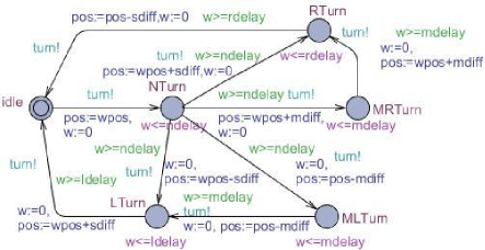
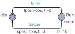
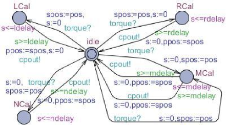
The SSU Papyrus UML model at Analysis level in EAST-ADL is transformed to an UPPAAL model under the verification criteria: For AFs, FunctionBehaviors are semantically translated into a network of TAs in terms of their corresponding artifacts and BA. The functional and quality requirements of the system were given as either informal description in ATESST2 project case study reports or as timing- or behavioral constraints requirement entities linked to AFs from BA. Due to space limitation, here we present only the UPPAAL TAs of Steering Wheel, Torque Sensor and Steering Column Calculator shown in Fig.8, Fig.9 and Fig.10 respectively.
The requirements formalized in UPPAAL logics over the network of TAs are verified by model-checking with some assumptions regarding timing: there is a data flow from a steering wheel to a motor actuator. The functions are periodic and mutually unsynchronized. A perfect clock is assumed in the sense that it generates periodic triggering in order to activate (run) the AFs with a periodicity of one time unit. Each function has its execution time which is modeled with an execution delay location in its TA. Based on those assumptions, properties of safety, deadlock freedom and liveness are verified successfully.
We verified 25 properties of the system. The evaluation conditions mentioned in Section 3 is referenced to formalize the properties. A list of selected properties is given below and their verification results are established as valid:
-
•
Deadlock freedom: 111A[ ] : ” holds for any reachable configuration” is written in UPPAAL format not deadlock
-
•
Leads-to property based on the internal variables of AFs: Every time Steering Column Calculator (SCC) is invoked by Steering Wheel or Torque Sensor, it will eventually calculate column positions for Pinion according to the steering position and torque force.
-
-
•
Leads-to property based on the interactive values via ports: If Steering Wheel sends out its position value then the value should be received by SCC.
-
-
•
State correspondence check: One internal location of an AF corresponds to what is happening in the locations of other environment AFs. While Steering Wheel is turning right, neither the left-column-calculating mode of SCC nor the left-rotation mode of Pinion is executing.
-
-
•
Execution time property: Each AF should execute within its given local execution time, .
-
-
•
Bounded liveness property: When Steering Wheel is activated, Actuator reacts timely under its given time bound (MAXTIME) as a failsafe against serious accident.
-
(
In other words, if Steering Wheel is invoked, it should not reach the error location of the observer TA, which violates the MAXTIME bounded condition, while Actuator is executing.
-
Search order is breadth first and uses conservative space optimization. The state space representation uses difference bound matrices (DBM). Verifying properties takes an average of around 2 seconds per verified property on an Intel T9600 2.80 GHz processor. The UPPAAL model checker needs to explore a maximum of 38166 states. The maximum is reached when verifying properties where the model checker needs to explore the whole sate space (such as the non-existence of a deadlock situation).
5 Related Work
For safety-driven system development in the automotive domain, feature- and architecture based analysis is prescribed by ISO standard as the state-of-the-art approach to functional safety. However, at an early stage it is difficult to see function dependencies that would result in updated function requirements. Therefore, A. Sandberg et al. [16] provide one approach that performs iterative analysis to manage changes in the safety architecture at analysis level and still meet function specific safety goals derived at vehicle level. In comparison to our work, their main concern is to define the semantics for requirement selection in order to ensure correct inclusion of requirements for a function definition. There is no formal modeling and verification approach to the behavioral definition of EAST-ADL.
L. Feng et al. [13] propose a reference behavior modeling approach which employs UML activity diagram, C code and SPIN to study the execution logic of the components and their communication protocol in EAST-ADL. Thus the requirements on the system design can be verified by model checking. In contrast to our work, there is no notion for the timing constraints in the behavior model. Indeed, formal analysis on the real-time properties of the behavior model is not considered at all.
The TIMMO project [10] introduces TADL (Timing Augmented Description Language). The language and its methodology [17] is aligned with EAST-ADL and AUTOSAR [11] for timing analysis aspects. In contrast to the TIMMO effort focused on its timing extension, our work focuses on the behavioral aspects complying with the timing extension. Therefore, our work contributes towards the development of the EAST-ADL behavioral extension.
Our earlier work [14] verifies EAST-ADL models using UPPAAL-PORT111http://www.uppaal.org/port. The work uses mainly structural information of EAST-ADL and its requirement, where models are manually translated into SAVE-CCM [18], which is the required input format for UPPAAL-PORT. In contrast to that work [14], we consider recent additions to EAST-ADL, including both the timing and behavior extensions by analyzing application internal behaviors specified in behavioral annex as well as using artifact packages. Furthermore, we eliminate the need for intermediate formalisms like SAVE-CCM and target direct transformation of EAST-ADL specifications to UPPAAL TAs.
Another widely used ADL within both industry and the research community for architectural modeling and analysis of time-critical software intensive embedded systems is Architecture Analysis and Design Language (AADL) [19]. S. Björnander et al. [20] propose an approach to formal and implemented semantics of AADL, where the Timed Abstract State Machine (TASM) [21] language is used as the formal underpinning. We take a similar approach by transforming EAST-ADL constructs to Timed Automata, especially UPPAAL TA, in order to allow tool-supported automated simulation and verification of EAST-ADL specification by using UPPAAL model checker. The result of our work contribute towards the development of EAST-ADL behavior extension [6] and further refinement of the existing behavior extension.
6 Conclusion and Future Work
In this paper, we have studied the use of formal modeling and verification techniques at an early stage in the development of safety-critical automotive products which are originally described in the EAST-ADL architectural language. We have proposed an architecture-based verification technique which brings formal modeling formalisms to the behavioral definitions of EAST-ADL to capture the execution flows inside each functional entity and their complex interactions and verify them by using the UPPAAL model checker.
This architecture-based modeling, analysis and verification methodology is suitable for a higher abstraction level, the current work focuses on the EAST-ADL analysis level, but can be extended to the design level. This will require only a change the type of functions and prototypes in the modeling process.
This paper has furthermore presented the criteria of EAST-ADL based verification technique. This criteria describes – 1. the selected constructs of EAST-ADL such as artifacts, structural Papyrus models, and BA as well as requirements which are utilized for the purpose of generating UPPAAL TA models or UPPAAL queries, and – 2. the conditions these objects have to meet.
Moreover, the formal syntax and semantics of EAST-ADL are defined, and this is essential for automated verification of EAST-ADL specifications, i.e., the formal definition enables the EAST-ADL model to be automatically transformed to models of other established tools for V&V support. Indeed semantics mapping rules are presented between EAST-ADL specifications and UPPAAL TAs under the verification criteria. These rules enable us to generate analyzable UPPAAL models from the EAST-ADL specifications.
These contributions improve behavior modeling, verification and analysis capability of EAST-ADL. To demonstrate the applicability of our approach, the steering system units case study has been translated from the EAST-ADL Papyrus model into the UPPAAL model. By employing the UPPAAL model checker, the verification of expected safety and liveness properties for this system are fully automated.
In future works, we plan to – 1. include more elaborate verification of non-functional properties, and more refined configurations of the generated model. For example, minimizing the use of certain resources, such as CPU, energy, memory, etc, while preserving functional correctness, timing requirements and other resource constraints. The results presented here are promising steps towards these goals, – 2. investigate schedulability analysis of timed-component models (source models from EAST-ADL) using UPPAAL in order to guarantee that the applied scheduling principle ensures that the timing deadlines are met. The planned enhancement includes consideration of functional design prototypes of EAST-ADL models in Papyrus UML at the design level as the source instead of using functional analysis prototypes at the analysis level as presented in this paper, and – 3. extend this work to verify the refinement process over different abstraction levels, i.e., to check if the basic features captured at the vehicle level are correctly refined (realized) in related functions at the analysis level as well as at the design level where the functionalities depicted at the analysis level are further decomposed or restructured.
References
- [1] “Advancing Traffic Efficiency and Safety through Software Technology Phase 2 (European project),” 2010. http://www.atesst.org.
- [2] A. Sangiovanni-Vincentelli and M. Di Natale, “Embedded system design for automotive applications,” Computer, vol. 40, no. 10, pp. 42–51, 2007.
- [3] K. Grimm, “Software technology in an automotive company - major challenges,” Software Engineering, International Conference on, vol. 0, p. 498, 2003.
- [4] M. Törngren, D. Chen, D. Malvius, and J. Axelsson., Automotive Embedded Systems Handbook: Model based development of automotive embedded systems. Taylor and Francis CRC Press, 2009.
- [5] “The ATTEST2 consortium, Methodology guidelines when using EAST-ADL Project Deliverable 5.1.1,” 2010.
- [6] “The ATTEST2 consortium, Update suggestions for behavior support, Project Deliverable 3.1, Appendix 3.4,” 2010.
- [7] “Simulation and Model-Based Design.” http://www.mathworks.nl/products/simulink/index.html.
- [8] G. Berhmann, A. David, K. G. Larsen, P. Pettersson, and W. Yi, “Developing uppaal over 15 years,” Software - Practice and Experience, December 2010.
- [9] R. Alur and D. L. Dill, “A theory of timed automata,” Theoretical Computer Science, vol. 126, no. 2, pp. 183–235, 1994.
- [10] “TIMing MOdel,” 2010. http://www.timmo-2-use.org/timmo/index.htm.
- [11] “AUTomotive Open System Architecture,” 2010. http://www.autosar.org.
- [12] J.-P. Katoen, Principles of Model Checking. MIT Press, 2008.
- [13] L. Feng, D. Chen, H. Lönn, and M. Törngren, “Verifying system behaviors in EAST-ADL2 with the SPIN model checker,” in IEEE International Conference on Mechatronics and Automation, (Xi’an China), August 2011.
- [14] E.-Y. Kang, P.-Y. Schobbens, and P. Pettersson, “Verifying functional behaviors of automotive products in EAST-ADL2 using UPPAAL-PORT,” in 30th International Conference on Computer Safety, Reliability and Security, pp. 243–256, Springer LNCS, vol 6894, September 2011.
- [15] “Open Source Tool for Graphical UML2 Modeling,” 2010. http://www.papyrusuml.org.
- [16] A. Sandberg, D. Chen, H. Lönn, R. Johansson, L. Feng, M. Törngren, S. Torchiaro, R. Tavakoli-Kolagari, and A. Abele, “Model-based safety engineering of interdependent functions in automotive vehicles using EAST-ADL2,” in Proceedings of the 29th international conference on Computer safety, reliability, and security, (Berlin, Heidelberg), pp. 332–346, Springer-Verlag, 2010.
- [17] “Tmmo open workshop, methodology version 2, project deliverable d5,” 2009.
- [18] J. Carlson, J. Håkansson, and P. Pettersson, “SaveCCM: An analysable component model for real-time systems,” in Proceedings of the 2nd Workshop on Formal Aspects of Components Software (FACS 2005) (Z. Liu and L. Barbosa, eds.), vol. 160 of Electronic Notes in Theoretical Computer Science, pp. 127–140, Elsevier, 2006.
- [19] P. Feiler, D. Gluch, and J. Hudak, “The Architecture Analysis and Design Language (AADL): An Introduction,” Tech. Rep. SEI-2006-TN-011, Society of Automotive Engineers, CMU, 2006.
- [20] S. Björnander, L. Grunske, and K. Lundqvist, “Timed simulation of extended AADL-based architecture specifications with timed abstract state machines,” in Proceedings of the 5th international conference on the quality of software architectures, pp. 101–115, Springer-Verlag, 2009.
- [21] M. Ouimet and K. Lundqvist, “The Timed Abstract State Machine Language: Abstract State Machines for Real-Time System Engineering,” Journal of Universal Computer Science, vol. 14, pp. 207–233, June 2008. http://www.jucs.org/jucs_14_12/the_timed_abstract_state.