*
\no*
\affiliateETIS Laboratory, ENSEA, Paris-Seine University
6 Avenue du ponceau, 95014 Cergy Cedex, FRANCE
Graduate School of Science and Technology, Nara Institute of Science and Technology
630-0192 Takayama-cho 8916-5, Ikoma-shi, Nara-ken, Japan
An FPGA-based centralized visible light beacon network
Abstract
Indoor localization systems based on Visible Light Communication (VLC) have shown promising advantages compared with systems based on other wireless technologies. In these systems, many VLC light-emitting diode (LED) anchors are employed in an indoor space in which location identification messages are sent to user devices in small packets. In normal beacon network models, micro-controller (MCU) or low-end system-on-chip (SoC) are often the coordinators which configure messages for one or many VLC-LED bulbs. In this paper, we discuss about processing overload and implementation cost of the two typical models of VLC beacon network in scenarios of a hundred of VLC-LED anchors are taken into account. Finally, an FPGA-based centralized VLC transmitter and its aided Nios II-based system has been introduced to enhance the performance of the VLC beacon network. Besides, due to the centralized processing, our system model is considered to be more cost-efficient than the dedicated-processor-based models.
keywords:
Centralized, FPGA-based, Indoor Localization, Visible Light Communication, Beacon Network.:
Optical systems
References
- [1] Wang, Qu , et al.: “Light positioning: A high-accuracy visible light indoor positioning system based on attitude identification and propagation model.” International Journal of Distributed Sensor Networks 14, no. 2 (2018), (DOI: 10.1177/1550147718758263).
- [2] Luo, Junhai, et al.: “Indoor Positioning Systems Based on Visible Light Communication: State of the Art” IEEE Communications Surveys & Tutorials 19, no. 4 (2017): pp.2871-2893, (DOI:10.1109/COMST.2017.2743228)
- [3] Chowdhury, Mostafa Zaman, et al.: “A comparative survey of optical wireless technologies: architectures and applications” IEEE Access 6 (2018): pp.9819-9840, (DOI:10.1109/ACCESS.2018.2792419).
- [4] Khan, Latif Ullah: “Visible light communication: Applications, architecture, standardization and research challenges” Digital Communications and Networks 3, no. 2 (2017): pp.78-88, (DOI:https://doi.org/10.1016/j.dcan.2016.07.004).
- [5] Zhuang, Yuan, et al.: “A survey of positioning systems using visible LED lights” IEEE Communications Surveys & Tutorials (2018) (DOI:10.1109/COMST.2018.2806558).
- [6] Japan Electronics and Information Technology Industries Association (JEITA), “Visible Light Beacon System”, ed, (2013).
- [7] Dinh-Dung Le, et al.: “Log-Likelihood Ratio Calculation Using 3-Bit Soft-Decision for Error Correction in Visible Light Communication Systems” IEICE Transactions on Fundamentals of Electronics, Communications and Computer Sciences, 101, no. 12 (2018): 2210-2212. (https://doi.org/10.1587/transfun.E101.A.2210)
- [8] Wu, Hongjia, et al.: “SmartVLC: When Smart Lighting Meets VLC” Proceedings of the 13th International Conference on emerging Networking Experiments and Technologies, ACM, (2017), pp.212-223, (DOI:10.1145/3143361.3149824).
- [9] Qiu, Kejie, et al.: “Let the light guide us: Vlc-based localization” IEEE Robotics & Automation Magazine 23, no. 4 (2016): pp.174-183, (DOI:10.1109/MRA.2016.2591833).
- [10] Li, Liqun, et al.: “Epsilon: A Visible Light Based Positioning System” In NSDI, vol. 14, (2014), pp. 331-343.
- [11] Hassan , et al.: “Indoor positioning using visible led lights: A survey” ACM Computing Surveys (CSUR) 48, no. 2 (2015): 20.
- [12] Tuan-Kiet Tran, et al.“Demonstration of A Visible Light Receiver Using Rolling-Shutter Smartphone Camera” In 2018 International Conference on Advanced Technologies for Communications (ATC), pp. 214-219. IEEE, 2018.
- [13] Tran, Thi Hong, et al.: “PER evaluation of K-min Viterbi decoder for wireless sensors” In 2016 10th International Conference on Sensing Technology (ICST), pp. 1-6. IEEE, 2016.
- [14] Nguyen DP, et al. “VLSI Architecture of Compact Non-RLL Beacon-based Visible Light Communication Transmitter and Receiver” arXiv preprint arXiv:1805.03398 (2018).
- [15] Rajagopal , et al.: “IEEE 802.15. 7 visible light communication: modulation schemes and dimming support.” IEEE Communications Magazine 50, no. 3 (2012).
- [16] Wang, He and Kim, Sunghwan: “Decoding of Polar Codes for Intersymbol Interference in Visible Light Communication” IEEE Photonics Technology Letters, (2018), (DOI:10.1109/LPT.2018.2831783).
- [17] Nguyen, Duc Phuc, et al.: “Hardware Implementation of A Non-RLL Soft-decoding Beacon-based Visible Light Communication Receiver” In 2018 International Conference on Advanced Technologies for Communications (ATC), pp. 208-213. IEEE, 2018.
- [18] Le, Dinh Dung, et al.: “Joint polar and run-length limited decoding scheme for visible light communication systems” IEICE Communications Express 7.1 (2018), pp.19-24, (DOI:https://doi.org/10.1587/comex.2017XBL0138).
- [19] Wang, He and Kim, Sunghwan: “Dimming Control Systems With Polar Codes in Visible Light Communication” IEEE Photonics Technology Letters 29, no. 19 (2017), pp.1651-1654, (DOI:10.1109/LPT.2017.2737026).
- [20] Fang, Junbin, et al.: “An Efficient Flicker-Free FEC Coding Scheme for Dimmable Visible Light Communication Based on Polar Codes” IEEE Photonics Journal 9, no. 3 (2017), pp.1-10, (DOI:10.1109/JPHOT.2017.2689744).
1 Background
Indoor Location-Based Services (ILBS) are getting more attractions from researchers and industry due to their realistic applications. Generally, there are many wireless technologies applied in current ILBS such as WiFi, Bluetooth, Ultrasound, radio frequency identification (RFID), Zigbee and so on [1, 2]. Recently, visible light communication (VLC)-based indoor positioning systems (IPS) which possess promising characteristics of high bandwidth, energy-efficient, long lifetime and cost-efficient, are becoming strong candidates in ILBS market [2, 3, 4, 5]. Consequently, VLC-based IPSs are now appeared in indoor public spaces, factories, logistics, shopping and healthcare facilities [5]. Recently, Japan Electronics and Information Technology Industries Association (JEITA) has standardized the visible light beacon system in which unique identification (ID) messages are transmitted from each VLC-LED bulb for purposes such as identifying objects and locations [6]. At the user’s device, photodiode-based or smartphone camera-based receivers decode the received light signals to retrieve the transmitted information [5, 7]. Finally, localization algorithms (e.g., proximity and triangulation) are executed by the firmware of user portable devices to estimate the location of the receiver.
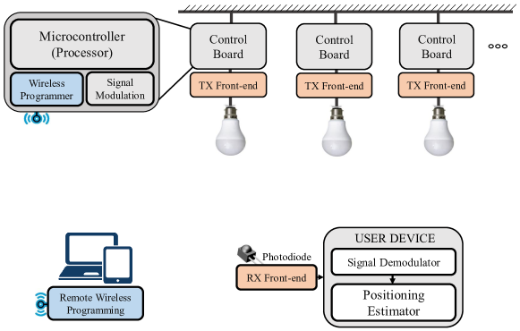
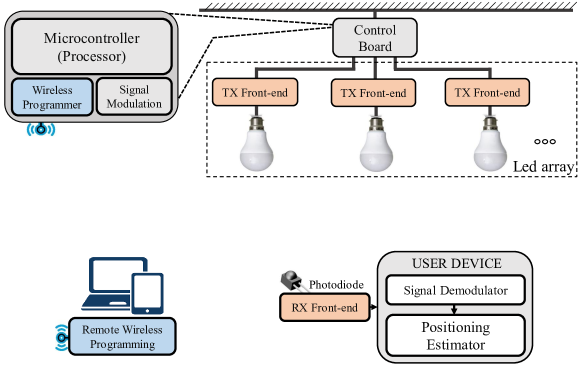
Fig.1a and Fig.1b shows two typical models of VLC-based IPSs. In beacon network presented at Fig.1a, each VLC-LED anchor is controlled by one control unit which we called dedicated-processor-based model [8, 9, 10]. Whereas, Fig.1b shows a beacon network in which LED array is controlled by one central processor, we called this model as central-processor-based model [5, 11]. In these two beacon network models, VLC transmitter’s procedures which including forward error correction (FEC) and run-length limited (RLL) encoding [4], are mainly processed by a firmware program on a low-end embedded processor. Besides, due to multiple LEDs are installed in an indoor space, the Signal Modulation block is required to execute multiplexing protocols, such as frequency division multiplexing (FDM) and time division multiplexing (TDM); this block ensures that signals from different LEDs can be differentiated at the receiver [11]. Furthermore, an optional part of the VLC transmit (TX) package is the wireless programmer which helps configure the firmware on the micro-controller or low-end SoC remotely [12, 8, 9]. At the receiver, signal demultiplexing and positioning algorithms are processed by a firmware program on user’s portable device.
2 Problem and related works
According to [5], system implementation cost is the first priority when considering the commercial availability of a VLC-based IPS design. In the dedicated-processor-based model (Fig.1a), considering this model is applied in a large building with hundreds or thousands of roof VLC-LED bulbs. In this scenario, the implementation cost increases linearly because each control board is dedicated for only one VLC-LED anchor [12, 8, 9, 10]. Moreover, each VLC-LED anchor takes more space to integrate the control board and TX front-end into the same VLC-LED package. Due to these reasons, the dedicated-processor-based model should be further considered to be applied in real commercial systems.
On the other hand, considering the central-processor-based model is applied with hundreds of LED anchors, and long wires are required to route from the central control board to LED bulbs via VLC TX front-ends (Fig.1b). In this scenario, transmitter’s essential procedures include encoding of FEC and RLL codes [13, 4, 14] are processed sequentially at the central control board’s firmware. Next, encoded messages are modulated and be forwarded to VLC TX front-ends. Although, FEC and RLL encoding are often not heavy computations. However, computation efforts increase when more LED anchors are installed in the beacon network. Hence, the central-processor-based model potentially causes critical delays in processing time of FEC, RLL or modulation routines. Moreover, due to the limited storage capability of most low-end embedded processor, the network scalability could be restricted.
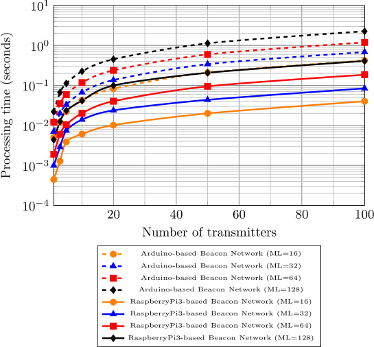
To confirm the statement, we have evaluated the consumed memories and processing delays of sequentially executing VLC transmitters’ procedures on Arduino Uno and Raspberry Pi 3 boards which are such two representatives between many low-end, low-cost MCUs and SoCs available on the market. Indeed, Reed-Solomon (RS) and convolutional codes (CC) are defined as FEC solutions in three operating modes of VLC transmitters [15]. Besides, Manchester and 4B6B codes are also defined as main candidates for RLL codes in low-speed PHY I operating mode [15, 17]. Recently, Polar-code-based FEC solutions and soft-decoding theories of RLL codes have been introduced to increase the performance of VLC systems [16, 18, 19, 20, 7]. In this paper, two Polar-code-based transmitters are selected to evaluate in two beacon network models. In the first transmitter, Polar encoding concatenated with Manchester RLL encoding are implemented. Whereas, 4B6B is selected as the RLL encoding solution for the second transmitter. Also, On-off keying (OOK) is selected as the modulation scheme because of its simplicity; and dimming support functions are not covered in the evaluation.
|
|
|||||
|---|---|---|---|---|---|---|
| ML=16, CL=32 | 452 bytes (22%) | 422 bytes (20%) | ||||
| ML=32, CL=64 | 644 bytes (31%) | 582 bytes (28%) | ||||
| ML=64, CL=128 | 1028 bytes (50%) | 902 bytes (44%) | ||||
| ML=128, CL=256 | 1796 bytes (87%) | 1542 bytes (75%) |
The Polar-code-based VLC transmitters’ procedures are described in Algorithm 1. We have implemented two VLC transmitters on Arduino Uno and Raspberry Pi 3 boards to evaluate the processing delays in different message lengths (ML) (ML = 16-bit, 32-bit, 64-bit, 128-bit), corresponding to different codeword lengths (CL) of Polar code (CL = 32-bit, 64-bit, 128-bit and 256-bit). The evaluation results are shown at Fig.2. We have found that processing delay increases linearly when number of transmitters increases in the beacon network; this is a critical point in any ILBS where users always expect real-time responses. Besides, Table 1 summarizes the amount of consumed global variables of transmitter’s procedures. Due to the limited dynamic memory of 2048 bytes, Arduino Uno consumes 22%, 31%, 50%, 87% of memory resource to storage all global variables (GV) of Manchester-based transmitter’s routines; with codeword lengths vary from 32, 64, 128 to 256 respectively. Also, in case 4B6B RLL encoding is applied with Polar encoding, smaller percentages of dynamic memory consumption are reported. However, in case of ML = 128 and CL = 256, the memory consumption rates of 87% and 75% might cause some instabilities when the system is in operation.
Evaluation results of processing time and consumed memory of central-processor-based VLC-LED beacon network (Fig.1b) have shown an critical processing delay when number of transmitters increases in beacon network. Besides, limited storage capabilities of low-end MCUs create barriers for this model to be applied in reality. On the other hand, due to the high-cost of implementation, the dedicated-processor-based VLC beacon network (Fig.1a) is also not a effective solution for real commercial systems. Therefore, in this paper, we introduce an FPGA-based centralized transmitter and its aided on-chip system, which can solve problems of processing delay and memory overload; and this solution is expected to support for a larger VLC beacon network.
3 Proposed system
To solve problems mentioned in Section 2, we have proposed a beacon network based on a centralized VLC transmitter and its aided Nios II system on FPGA. Specifically, FPGA-based centralized beacon network enables all messages could be processed at the central FPGA-based transmitter before encoded messages are passed to TX front-ends. Altera DE2-115 board which features Cyclone IV FPGA chip is selected to implement our system. Indeed, due to the parallel operating capabilities of the FPGA-based logic circuits and many pins are available on common FPGA devices. Many VLC front-ends can be covered by our FPGA-based central processing node.
3.1 A Nios II system for re-configuration
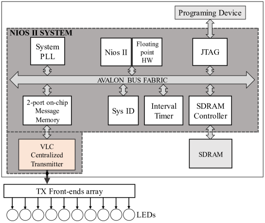
An overview of reconfiguration system is presented briefly in Fig.3. The Nios II system includes some basic blocks of any typical system on programmable chip (SoPC). Specifically, the system includes one Nios II soft-processor with specialized hardware for floating point calculations; a JTAG block which connect to programing, debug and monitoring device. Besides, an 64MB SDRAM off-chip is used to store the firmware, an interval timer helps measure the processing time of program. Besides, a 2-port on-chip memory is proposed to storage all uncoded messages of all front-ends in beacon network. In our system, 128-bit is the maximum size of each message, while 100 is the number of front-ends selected for evaluation. Therefore, the 2-port message memory with 1600 bytes can be extended to serve a larger beacon network because of plentiful availability of FPGA’s on-chip memory bits. In addition, the system is configured to operate at frequency of 50 Mhz (sys_clk) which is created from internal phase-locked loop (System PLL).
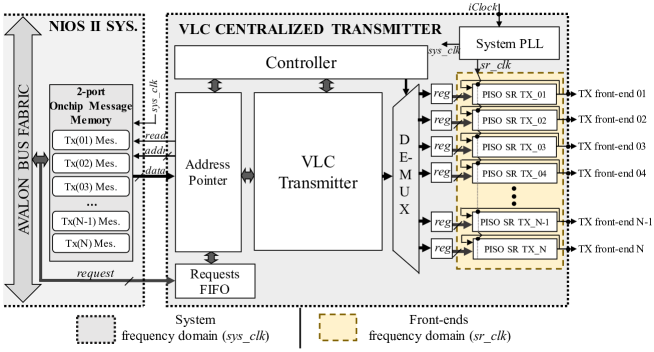
3.2 VLC Centralized Transmitter
Fig.4 describes the hardware architecture that we have implemented for the centralized transmitter. An explanation of this architecture can be divided into 5 parts.
3.2.1 Clock domains
There are two clock domains in the design: system clock (sys_clk = 50 Mhz), and clock for shift registers (sr_clk = 100 Khz). These two clocks are created from the System PLL with the reference clock (iClock = 50 Mhz). In addition, the VLC TX front-ends transmit information at the same frequency with shift registers’ frequency (sr_clk), and this frequency could be adjusted following requirements of the expected VLC system.
3.2.2 Requests FIFO and Address Pointer
In general cases, the VLC-based IPS initially configures new ID messages for all LED bulbs when IPS is first settled in some indoor spaces. However, there are some scenarios that messages are determined to send to some appointed LED bulbs. In these scenarios, there is no need to update messages for all LED anchors. Therefore, the our centralized transmitter stores all write requests sent to 2-port message memory. Each request is a combination of signals: write request, address, and data to write. In our design, each request is an 136-bit signal which includes 128-bit of message. A (first-in first-out) FIFO buffer is used to storage requests. The Address Pointer checks the busy status of the VLC Transmitter; then it reads one request stored in FIFO and execute the request. The requests are executed by issuing read request (read) and address signal (addr) to the second interface of the 2-port on-chip message memory (Fig.4). Next, when Address Pointer achieves message from the memory interface (data), the acquired message is forwarded to VLC transmitter for FEC and RLL encoding procedures.
3.2.3 VLC Transmitter
In Section 2, we have introduced two VLC transmitters that we have implemented for evaluation. Particularly, the first transmitter includes procedures of Polar and Manchester RLL encoding; while the second transmitter procedures are the concatenation of Polar encoding with 4B6B RLL encoding. These two transmitters are recently mentioned in [16, 18, 19, 20]. In these two transmitter, the Polar encoders are implemented with architecture inherited from our previous work [17, 14]. As mentioned earlier, dimming control function is not implemented in these two transmitters. The reason is, although puncturing and compensation symbols (CSs) are purely simple routines; however, these procedures require many storage bits on variable memory, which has been demonstrated about its limitation in Section 2. Hence, dimming control block is neglected in our hardware implementation for a fair comparison with Arduino-based model.
3.2.4 De-multiplexer and registers
After the message is processed by VLC transmitter block, it is expected to be distributed to appointed front-end. Therefore, a de-multiplexer (DE-MUX) determines the front-end registers that the message should be passed, and the (DE-MUX) is controlled by a memory-read address that Address Pointer has issued. Also, we have implemented loop parallel-input serial-output shift-registers (PISO SRs) which can repeat the encoded messages while there is no new messages come to front-ends. PISO SRs are operated in front-end frequency domain (sr_clk). Besides, buffering registers (reg) are inserted between DE-MUX and PISO SRs to buffer the message.
3.2.5 Controller
The Controller block handles the operation of VLC centralized transmitter. Specifically, it controls the start and finish of the VLC Transmitter; acquires the memory-read address from the Address Pointer and gives control signals to DE-MUX.
4 Experimental results
The proposed architecture of VLC centralized transmitter is described by synthesizable Verilog HDL language. ModelSim is used as the verification tool. The Nios II system is created with the helps of Platform Designer tool. Nios II Software for Eclipse is used for firmware programing and debugging. Our system is synthesized by Intel’s Quartus II. Table 2 summarizes the synthesis report of Nios II system on Cyclone IV FPGA device. It can be noticed that the Nios II system only consumes 1% of memory bits of Cyclone IV FPGA; this means that on-chip message memory can be further extended to serve for a larger number of TX front-ends in a larger beacon network. Besides, Table 3 shows the synthesis report of the Manchester-based and 4B6B-based VLC centralized transmitters. In particular, due to a better code rate, the transmitter based on Polar and 4B6B RLL encoding consumes less logic elements (LE), look-up tables (LUT) and registers than the Manchester-based transmitter does. However, due to the storage of 4B6B mapping tables, amount of consumed memory bits of 4B6B-based transmitter is larger than the Manchester-based one. Besides, our FPGA-based centralized transmitters occupy 102 pins in the total of 529 pins of Cyclone IV FPGA (19%). Indeed, we have just implemented an architecture which only supports 100 front-ends for evaluation; however, the availability of unused pins enables more front-ends can be supported. Additionally, both transmitters can achieve maximum throughputs higher than 600 Mbps; therefore, our FPGA-based centralized transmitter could be potentially applied in high-speed VLC systems. Furthermore, Table 4 shows resource summary of the centralized transmitters and their components. It can be seen that the de-multiplexer, buffering registers and PISO shift registers occupy most of logic cells in both centralized transmitters. However, instead of using logic cells to implement shift registers, we can utilize embedded memory bits which are still abundant in Cyclone IV FPGA to reduce the total logic cells of the system.
| Nios II System | |
| Device | Cyclone IV FPGA |
| Model | 1200 mV, |
| Fmax | 80.25 Mhz |
| LE/LUT | 12166/114480 (11%) |
| Registers | 7479 |
| Memory bits | 54713/3981312 (1%) |
| Embedded Multiplier | 15/532 (3%) |
| Total PLLs | 1/4 (25%) |
| FEC, RLL | Polar, Manchester | Polar, 4B6B |
| Device | Cyclone IV FPGA | Cyclone IV FPGA |
| Number of front-ends | 100 | 100 |
| Model | 1200 mV, | 1200 mV, |
| Fmax | 76.13 Mhz | 69.69 Mhz |
| Code length | 256 | 256 |
| Code rate | 1/4 | 1/3 |
| LE/LUT | 91518/114480 (80%) | 78823/114480 (69%) |
| Registers | 91004 | 78274 |
| Memory bits | 277/3981312 (1%) | 6425/3981312 (1%) |
| Total pins | 102/529 (19%) | 102/529 (19%) |
| Total PLLs | 1/4 (25%) | 1/4 (25%) |
| Latency | ||
| ( domain) | 14 clock cycles | 14 clock cycles |
| Maximum throughput | 694.8 Mbps | 630.8 Mbps |
| Instance | Logic Cells | Registers | Mem.‡ | LUT/Reg.† |
|---|---|---|---|---|
| Request FIFO | ||||
| Address Pointer | ||||
| Controller | ||||
| VLC Transmitter | ||||
| De-multiplexer | ||||
| Front-end regs | ||||
| PISO Shift reg. | ||||
| Total |
†LUT/Registers Logic Cells
‡Embedded memory bits
| No. of Transmitter | FPGA/Arduino Gain | FPGA/Raspberry Gain |
| 1 | 2729 | 548 |
| 3 | 3969 | 738 |
| 5 | 4609 | 966 |
| 10 | 4610 | 850 |
| 20 | 4465 | 985 |
| 50 | 4375 | 802 |
| 100 | 4359 | 789 |
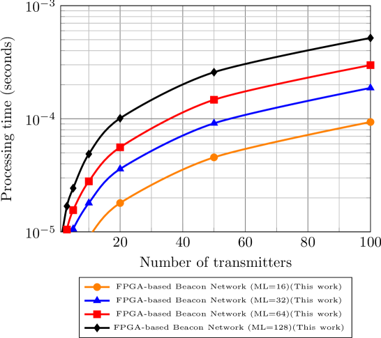
Fig.5 shows the processing delay evaluation of our FPGA-based centralized beacon network. Besides, Table 5 summarizes the processing delay improvement of FPGA-based beacon network. Specifically, improvements of maximum 4610 times and 966 times are reported for processing delay of FPGA-based solution compared evaluation results on Arduino Uno and Raspberry Pi 3, respectively (Fig.2 and Fig.5).
5 Conclusion
In this paper, we have introduced an FPGA-based centralized beacon network. Our proposal includes a hardware architecture for the centralized VLC transmitter which can process messages for all TX front-ends in beacon network; and a Nios II-based system to control the messages and operation of the beacon network. Experimental results have shown that our system can improve the processing delay of the central-processor-based beacon networks remarkably. Besides, our FPGA-based model can be extended to serve for a large beacon network which includes many VLC-LED bulbs due to the abundant availability of embedded memory bits and FPGA’s pins. Moreover, compared with beacon networks which based on dedicated embedded processors, our FPGA-based centralized system is expected to reduce the implementation cost of the commercial VLC-based positioning systems.
Acknowledgments
This work was supported by JSPS KAKENHI Grant Number JP16K18105.