Electric control of spin transport in GaAs (111) quantum wells
Abstract
We show by spatially and time-resolved photoluminescence that the application of an electric field transverse to the plane of an intrinsic GaAs (111) quantum well (QW) allows the transport of photogenerated electron spins polarized along the direction perpendicular to the QW plane over distances exceeding 10 m. We attribute the long spin transport lengths to the compensation of the in-plane effective magnetic field related to the intrinsic spin-orbit (SO) interaction by means of the electrically generated SO-field. Away from SO-compensation, the precession of the spin vector around the SO-field decreases the out-of-plane polarization of the spin ensemble as the electrons move away from the laser generation spot. The results are reproduced by a model for two-dimensional drift-diffusion of spin polarized charge carriers under weak SO-interaction.
pacs:
72.25.Dc, 72.25.Rb, 71.70.Ej, 78.67.DeI Introduction
The manipulation of electron spins in semiconductors has attracted much interest during the last years due to potential applications for quantum information processing.Awschalom et al. (2002); Zutic et al. (2004) Devices based on semiconductor spins require efficient techniques for the generation, storage, transport, and detection of the spin polarization, as well as interaction mechanisms for the manipulation of the spin vector in times shorter than the characteristic spin lifetime. One of the main challenges towards this goal in III-V semiconductor structures is the suppression of decoherence processes associated with the spin-orbit (SO) interaction, which reduces the lifetime of the electron spin polarization to values typically below one nanosecond and thus severely restricts its application in spintronic devices.
The SO-interaction describes the coupling between the spin vector and the varying lattice potential acting on a moving electron. In the electron reference frame, the SO-interaction translates into an effective magnetic field, , which can lead to spin dephasing in an electron ensemble. Since depends on the electron’s wave vector, , its magnitude and direction changes after each electron scattering event. As a result, electron spins with the same initial polarization but moving with different wave vectors will precess around different axes with different Larmor frequencies in-between two consecutive scattering events, leading to the well-known Dyakonov-Perel’ (DP) spin dephasing mechanism.D’yakonov and Perel’ (1972); D’yakonov and Kachorovskii (1986) Improvement of the electron spin lifetime in these materials demands, therefore, the control of spin dephasing related to the SO-interaction.
In GaAs-based quantum well (QW) structures, the SO-interaction is governed by two major contributions. The first one is associated with the bulk inversion asymmetry (BIA) of the zinc-blende lattice. This contribution, known as the Dresselhaus hamiltonian,Dresselhaus (1955) , is expressed as:
| (1) |
where is the reduced Planck constant, are the Pauli matrices, are the wave-vector components along , and is the Dresselhaus spin-splitting constant of the material (we follow here the convention introduced by CardonaChristensen and Cardona (1984); Cardona et al. (1988) and EppengaEppenga and Schuurmans (1988)).
The second important contribution to the SO-interaction arises from the structural inversion asymmetry (SIA) introduced by an external field. In most cases, the SIA is generated by an electric field, , leading to the Rashba Hamiltonian, :Bychkov and Rashba (1984)
| (2) |
where is the Rashba coefficient.Winkler (2003) Since the strength of depends on , the Rashba contribution provides a powerful mechanism for the electric manipulation of the spin vector.
The impact of the SO-interaction on the electron spin dynamics depends on the crystallographic growth direction of the QW.D’yakonov and Kachorovskii (1986) In the last years, GaAs QWs grown along the direction have attracted an increasing interest due to the special symmetry of the Dresselhaus and Rashba effective magnetic fields in this case. In the reference frame defined by the axes , , , and for a QW subjected to a transverse electric field , these two contributions can be expressed as:Cartoixa et al. (2005)
| (6) | |||
| (10) |
| (11) |
Here, is the averaged squared wave vector along determined by the spatial extension of the electron wave function, , and is the in-plane wave vector amplitude. At low temperature and electron populations, quadratic terms in and can be neglected, so that both and lie in the QW plane and have exactly the same symmetry. As a result, by adjusting to satisfy the condition:
| (12) |
the SO-interaction becomes simultaneously suppressed for all values of at a well-defined compensation electric field, , leading to long electron spin lifetimes. This compensation mechanism was originally proposed in the theoretical works by CartoixàCartoixa et al. (2005) and Vurgaftman.Vurgaftman and Meyer (2005) Recent experiments have provided evidence for the electric enhancement of the spin lifetime,Balocchi et al. (2011); Biermann et al. (2012) as well as for the transition from a BIA-dominated to a SIA-dominated spin dephasing with increasing electric field.Hernández-Mínguez et al. (2012) The effects of the non-linear k terms in on the compensation mechanism have also been addressed.Sun et al. (2010); Wang et al. (2013a); Balocchi et al. (2013); Hernández-Mínguez et al. (2014)
A further important requirement for the efficient use of the spin degree of freedom in semiconductor devices is that carriers must be able to move from one point of the semiconductor to another one without losing their spin polarization. This requires not only long spin decoherence times but also good spin transport properties. Studies of spin diffusion in GaAs have been performed in the last years in bulk,Kikkawa and Awschalom (1999); Crooker et al. (2005); Yu et al. (2009); Quast et al. (2009, 2013); Weber et al. (2011); Henn et al. (2013) as well as in intrinsic,Cameron et al. (1996); Eldridge et al. (2008); Zhao et al. (2009); Hu et al. (2011); Henn et al. (2014) and n-doped QWsWeber et al. (2005); Carter et al. (2006); Völkl et al. (2011, 2014); Altmann et al. (2014); Kohda et al. (2015); Altmann et al. (2015) grown along different orientations. Although the spin transport properties were initially supposed to be the same as those of the charge, several results showed that this is not always true: while the charge transport in a carrier ensemble is not affected by carrier-carrier elastic scattering, this kind of interaction can play an important role in the case of spin transport. An example of this different behavior between carrier and spin transport is the spin Coulomb drag mechanism observed during unipolar spin diffusion in n-doped QWs.D’Amico and Vignale (2001); Weber et al. (2005)
It has been recently shown that the spin diffusion length in GaAs (111) QWs can be efficiently controlled by a transverse electric field induced by a top electric gate.Wang et al. (2013b) Of special importance for future applications is the relation between the spin and carrier transport in these structures. In this contribution, we report experimental studies of both charge and spin transport in an intrinsic GaAs (111) QW under the effect of vertical electric fields. In our experiments, a cloud of out-of-plane spin polarized electron-hole (e-h) pairs is optically generated by a tightly focused laser beam, and the expansion of this cloud under a transverse electric field is studied by spatially and time-resolved -photoluminescence (PL). We show that the transport properties of out-of-plane electron spins depend on the applied electric field. We propose an explanation based on the precession of the spin vector around a weak in-plane SO-field during the radial expansion of the electron-hole cloud, finding a good agreement between simulation and experimental data. At SO-compensation, the suppressed precession of the spin vector around the SO-field allows the transport of the out-of-plane spin polarized electrons over distances exceeding m. Under these conditions, the decay of the electron population in a few nanoseconds due to electron-hole recombination is the main mechanism limiting the spin transport distance.
This manuscript is organized as follows: in Section II we introduce the sample design and the experimental techniques for the optical injection and detection of spin-polarized carriers. Section III.1 shows the experimental results of charge transport obtained from both time-integrated and time-resolved experiments. Section III.2 shows the corresponding results for the case of spin transport, followed by a discussion of a spin drift-diffusion model in Section IV. Finally, Section V summarizes the main points of our work.
II Experimental details
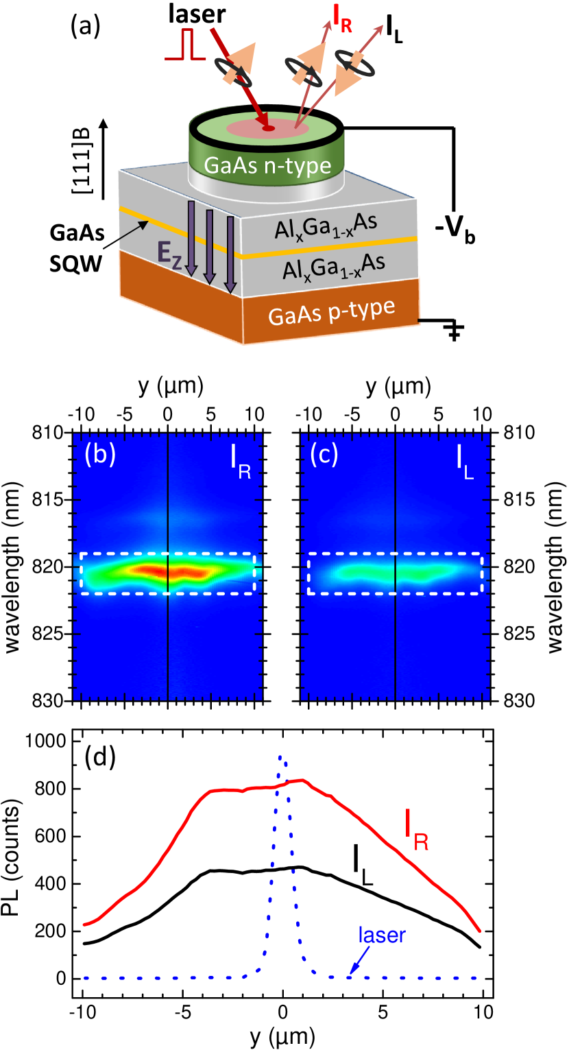
The experiments reported here were carried out in an undoped single GaAs/AlGaAs QW with a thickness of 25 nm embedded in the intrinsic region of a p-i-n diode structure, cf. Fig. 1(a). The sample was grown by molecular beam epitaxy on a -doped GaAs(111)B substrate tilted by a small angle () towards the -direction (further details about the sample growth process can be found at Ref. Hernández-Mínguez et al., 2014). The bias voltage, , applied between an Al Schottky contact on top of the -doped layer and the -doped substrate, generates the vertical electric field required for the control of the SO-interaction. From previous measurements in a similar sample, we expect to reach at a reverse voltage bias V.Hernández-Mínguez et al. (2012, 2014) To confine the electric field along the -direction, we processed the top doped layer and part of the top undoped (Al,Ga)As spacer into mesa structures of 300 m diameter defined by wet chemical etching.
The spectroscopic studies were carried out with the sample in a cold finger cryostat at a temperature K equipped with a window for optical access and electric feed-throughs for the application of bias voltages. We optically excited e-h pairs with spin vector pointing perpendicular to the QW plane by using a circularly polarized, pulsed laser beam with wavelength of 756 nm, pulse width of 150 ps, and repetition rate of 40 MHz. The beam was spatially filtered and tightly focused onto a spot with a diameter (full width at half maximum) m by a 50 microscope objective. The carrier cloud generated by the laser beam spreads outwards leading to a PL area extending over several m around the generation spot. This PL was collected by the same objective and split into two beams with intensity proportional to its left () and right () circular components, which were then imaged by a cooled charge-coupled detector (CCD) placed at the output of a spectrometer. The input slit of the spectrometer was placed parallel to the surface direction of the sample, so that the images of and were collected at the CCD with energy (vertical scale) and spatial resolution along (horizontal scale). In addition to spatially resolved, time-integrated profiles, we have also recorded time-resolved profiles by using a gated CCD camera synchronized with the laser pulses.
and were used to determine the time and spatial dependence of the carrier density, (we suppose because the QW is non-doped), as well as the out-of-plane spin density . As the spin polarization of the photoexcited holes is lost within a time (few picosecondsDamen et al. (1991); Hilton and Tang (2002)) much shorter than the e-h recombination lifetime, the difference between and only gives information about the out-of-plane component of the electron spin vector within the e-h ensemble. The out-of-plane spin polarization, , was obtained according to . We limit the use of , however, to time-integrated measurements, where the number of counts in the CCD for both and is significantly above the noise signal everywhere along . As this is not always true in time-resolved experiments, in this case we only discuss to avoid dealing with meaningless values of the division .
III Results
III.1 Carrier dynamics
Figures 1(b) and (c) compare time-integrated images of and recorded with spectral (vertical axis) and spatial resolution (horizontal axis) for V. The position of the 1 m-wide laser spot used for excitation is . The dashed rectangles indicate the PL emitted by the electron-heavy hole (e-hh) transition. Figure 1(d) shows the corresponding intensity profiles of and for the e-hh transition as a function of the distance to the laser spot, while the dotted line displays, for comparison, the intensity profile of the tightly focused laser beam. As expected, the e-hh emission region extends over an area much larger than the diameter of the excitation spot due to the radial ambipolar transport of photogenerated electrons and holes. The shape of the measured PL profile deviates from the expected one, symmetric to , due to terraces at the sample surface, which originate from the growth on a surface tilted by an angle with respect to the [111] direction.Hernández-Mínguez et al. (2014)
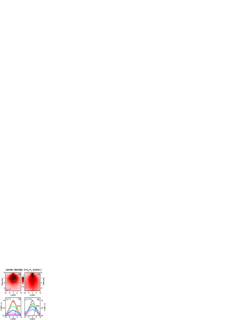
We have also performed time-resolved -PL experiments using a time-gated CCD camera. Figure 2(a) shows a two-dimensional color plot of the carrier density, , as a function of the position along (horizontal scale), and the time delay with respect to the laser pulse (vertical scale) for V. Panel (b) displays the corresponding spatial profiles at the times marked with dashed lines in panel (a). After a fast initial expansion during the first nanosecond, the carrier motion slowers for longer time delays while also decays due to e-h recombination. In contrast, when V (corresponding to an electric field close to ), the carrier expansion lasts longer, cf. panels (c-d). We attribute this behavior to the reduction of the e-h recombination rate due to the electrically induced spatial separation of the electron and hole wave functions toward opposite barriers of the QW.
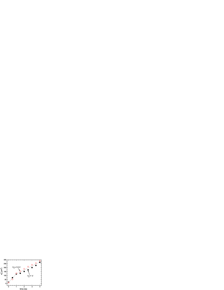
We can obtain the ambipolar carrier diffusion coefficient, , and the e-h recombination time, , from these time-resolved measurements by assuming that the optically generated carrier density, , has an initial Gaussian shape. Under these conditions, the expansion of as a function of time, , and radial distance, , is described by the solution to a two-dimensional drift-diffusion model:Zhao et al. (2009)
| (13) |
where is the carrier density at and , is the full width at half maximum (FWHM) of the initial carrier distribution, and is the FWHM of the profile as a function of time. Figure 3 shows values of obtained from the fits of Eq. 13 to the profiles in Figure 2 at several time delays. The high quality of the fits is demonstrated by the solid lines superimposed on the experimental points in Figs. 2(b) and 2(d). For both applied biases, initially increases with a fast slope during the first nanosecond, followed by a slower evolution for larger time delays. We attribute the fast expansion just after the pulse ( ns) to repulsive drift forces between carriers at the high density regions close to the generation spot. As the e-h pairs were non-resonantly generated by the laser, an initial higher carrier temperature with respect to the lattice also contributes to the fast expansion with an initially higher diffusion coefficient. The evolution at ns is due to the radial transport of the thermalized electrons and holes driven by diffusion. From the linear fitting of in this regime, we obtain cm2/s. It is remarkable that, although the increase of enhances the e-h recombination time from ns to 4 ns, is not significantly affected. To estimate the carrier scattering time, , from , we take into account that the Fermi energy for the carrier density present in the QW at ns is lower than the thermal energy. We can therefore apply the Einstein equation , where is the electron charge, is the Boltzmann constant, and is the ambipolar mobility , whose value is intermediate between the electron and heavy hole mobilities, and respectively. Our result is ps, in agreement with previously estimated values in a similar QW based on measurements of Dyakonov-Perel’ spin dephasing time under homogeneous carrier concentration.Hernández-Mínguez et al. (2012, 2014)
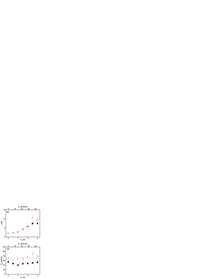
We have repeated the previous experiment for several voltage biases and laser powers, , to extract the dependence of and on and carrier density. Figure 4 shows (a) and (b) as a function of obtained from measurements performed at W (squares) and 80 W (circles). The top horizontal scales depict the that corresponds to the applied , which was determined from the energy shift of the PL due to the Quantum Confined Stark Effect (QCSE).Hernández-Mínguez et al. (2014) As expected, the spatial separation of electron and hole towards opposite QW barriers induced by increases the carrier lifetime. , on the contrary, does not depend on applied bias. It increases, however, with the laser power, from 50 cm2/s at 40 W to 70 cm2/s at 80 W. We attribute the increase to the fact that a larger carrier concentration screens more efficiently the scattering centers that limit the carrier mobility in the structure.Remeika et al. (2009) An additional cause of this enhancement is that, for W, the Fermi level approaches the thermal energy at the time range studied. Above this limit, becomes proportional to the carrier density.
III.2 Spin dynamics
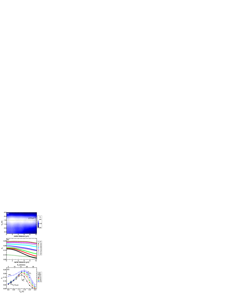
The large extension of the time-integrated PL profiles of Fig. 1 relative to the laser spot diameter allows to determine the out-of-plane spin polarization, , as the carriers move away from the excitation point. Figure 5(a-b) shows vs. the radial distance, , calculated from the time-integrated and profiles under different biases . The experiment was performed using a laser power W. Figure 5(c) compares the values of at the generation spot, (open diamonds), and at a radial transport distance, , of 10 m (solid diamonds) as a function of and its respective . At , decays from 0.16 at to 0.07 at due to spin precession around the SO-field between scattering events as the carriers move away from the generation spot. When the bias approaches V, the linear Dresselhaus and the Rashba term cancel each other and the SO-interaction is suppressed. As a consequence, the electron ensemble expands without losing its initial out-of-plane spin polarization. Therefore, remains constant around all along the transport distance studied. At biases V, the Rashba term overcompensates the Dresselhaus one. The SO-interaction becomes then active again and decreases. The observation of a maximum in at V unambiguously establishes the BIA/SIA compensation as the mechanism for electrically induced spin transport enhancement in (111) QWs. The corresponding value of kV/cm agrees well with PL results recorded in a similar sample using a larger illumination area.Hernández-Mínguez et al. (2012, 2014)
It is noteworthy that the profile for in Fig. 5(c) is asymmetric with respect to the compensation bias V. The asymmetry arises from the fact that, in a time-integrated PL measurement, depends on the ratio between the carrier recombination time, , and the spin dephasing time, , according to:
| (14) |
Here, is the maximum electron spin polarization that can be achieved for excitation energies above the electron-light hole transition.Meier and Zakharchenya (1984) While increases monotonously with , cf. Fig. 4(a), has a maximum at and decreases as the electric field moves away from the compensation field.Cartoixa et al. (2005); Vurgaftman and Meyer (2005); Hernández-Mínguez et al. (2012) Therefore, when exceeds , and at goes to zero because the out-of-plane spin polarization is lost much before the electrons and holes recombine.
We have repeated the experiment of Fig. 5(a) using several laser excitation powers, cf. Fig. 5(c). As the number of optically injected carriers increases, we observe an enhancement of at , . To understand this, we take into account that the photons detected at this point are emitted by e-h pairs that recombine just after traveling from the generation spot to in an average time . We have shown in Fig. 4(b) that increases with laser power, thus reducing the traveling time of the carriers. As a consequence, a larger fraction of electrons reaches before losing their out-of-plane spin polarization.
In addition, larger laser powers shift by an amount towards larger values. We exclude thermal effects as the cause of this shift: higher temperatures would allow the occupation of energy states with larger -vectors, whose contribution to the cubic terms of reduces .Vurgaftman and Meyer (2005); Hernández-Mínguez et al. (2012, 2014); Balocchi et al. (2013) We attribute the enhancement of to a partial screening of the electric field generated by the top gate. This screening comes from the accumulation of photoexcited electrons and holes at opposite walls of the QW as a response to the gate field.
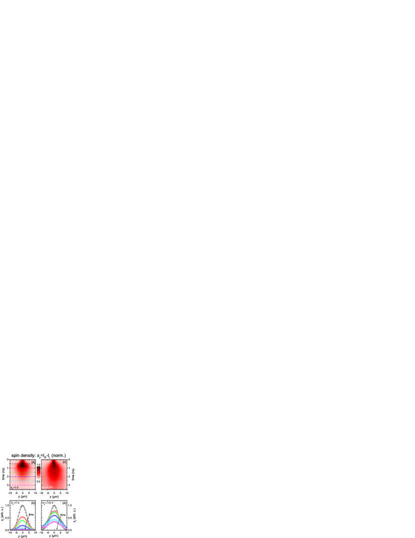
Finally, we have also measured the time-resolved radial expansion of the out-of-plane spin density, , in the same way as we did for in subsection III.1. Figure 6 shows the spatial- and time-resolved evolution of corresponding to the carrier dynamics of Figure 2. As in the case of , expands over an area much larger than the diameter of the excitation spot. A comparison of the temporal decay of and for V (panels (a-b) of Figures 2 and 6) shows that the amplitude of decreases slightly faster than due to the fact that the decay of includes spin dephasing in addition to carrier recombination. On the contrary, for the compensation bias V (see panels (c-d) in the same figures), the amplitude decays of and are very similar. The latter is attributed to a negligible spin dephasing within the recombination lifetime of the carriers due to SO-compensation. The decay of the spin density must, therefore, follow the one of the carrier density. As the lifetime of the photogenerated carriers is only a few nanoseconds, the main mechanism limiting spin transport in intrinsic GaAs (111) QWs at SO-compensation is electron-hole recombination.
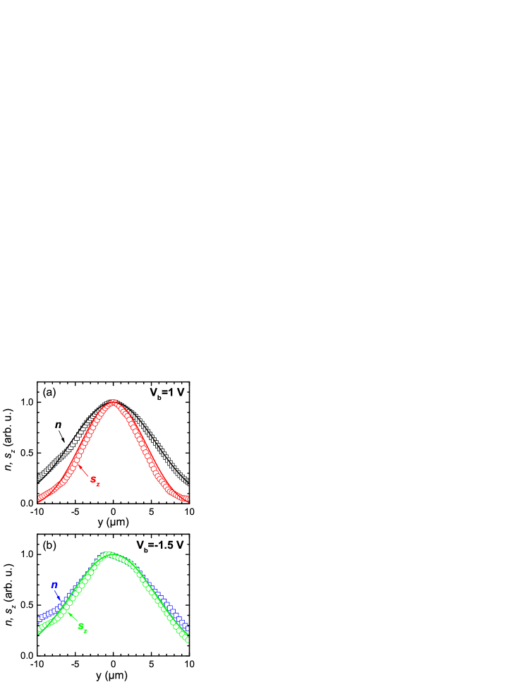
Interestingly, the spatial extension of also depends on . Figure 7 compares the normalized profiles of (squares) and (circles) at ns for (a) V and (b) V. In the case of V, the profile of , with a FWHM of m, is clearly narrower than the one of (m). When V, in contrast, both profiles have a similar spatial extension of m and m, respectively. The discrepancy in the profile widths for biases away from SO-compensation is due to the coherent precession of the spin vectors around the SO-field during the two-dimensional expansion of the inhomogeneous electron population. When the Dresselhaus and Rashba terms fulfill special symmetries, the interplay between the Brownian motion of the carriers and the spin-orbit field can correlate the orientation of the spin vector at spatially separated points in the electron ensemble.Froltsov (2001); Stanescu and Galitski (2007); Yang et al. (2010); Poshakinskiy and Tarasenko (2015) The most extreme example is the persistent spin helix observed in GaAs (001) QWs for a particular ratio between the Dresselhaus and Rashba terms.Bernevig et al. (2006); Koralek et al. (2009); Walser et al. (2012) In GaAs (111) QWs, the linear Dresselhaus contribution and the Rashba one have the same symmetry. Therefore, the SO-interaction at low temperatures can be treated as a single in-plane term with the symmetry of the Rashba contribution. In this case, the two-dimensional expansion of an initially narrow out-of-plane spin ensemble leads to oscillations of along in the momentum space that are described by a Bessel function.Stanescu and Galitski (2007) These Bessel-like oscillations are also present in the analytic solution of at times fulfilling , with the first node appearing at .Froltsov (2001); Stanescu and Galitski (2007); Poshakinskiy and Tarasenko (2015); Altmann et al. (2015) In our experiments, the maximum radial distance is m and the ambipolar diffusion coefficient is cm2/s, thus leading to ns. The e-h recombination time in our sample is, however, only a few nanoseconds, cf. Fig. 4(a). The spin density profiles of Figs. 6 and 7 correspond, therefore, to the opposite limit , where no analytic solution in the spatial domain exists.Stanescu and Galitski (2007) In addition, the value of for the range of applied voltage biases (cf. Fig. 8) implies that the first node appears at radial distances exceeding . This means that the optically injected e-h pairs disappear well before the oscillation of along can be observed.
IV Discussion
It is possible to obtain an analytic approximation to in the real space for if we take into account that, for the short carrier lifetime and weak SO-interaction of our experiment, the precession angle of the spin vectors in the ensemble is expected to be small. Under this assumption, the spatial profile of will resemble that of and can be approximated by:
| (15) |
Here, the cosine accounts for the projection along of the tilted spin vector due to its slight precession around during the radial expansion.111Although a Bessel function is a more appropriate solution for a radially symmetric differential equation than a harmonic oscillation, both functions behave similar for . To determine the precession angle of the spin ensemble, we proceed as follows: during an infinitesimal time interval , an electron spin vector moving with an in-plane momentum rotates an infinitesimal angle . Taking into account only the linear in-plane terms in Eq. 6, and using the relations and , we can express as:
| (16) |
| (17) |
Here, is the SO-precession angle per unit distance, and it fulfills . In our model, we assume that, during the early stage of the expansion process, the carriers generated within the laser spot follow a trajectory close to the radial one. This means that the instantaneous velocity of each carrier can be expressed as . Here, is the average radial velocity of the carrier ensemble, which is determined by the solution of the drift-diffusion differential equation, cf. Eq. 13. , on the contrary, is a perturbative random term that changes magnitude and direction after each scattering event. According to these definitions, the average precession angle, , of the carriers contained in an infinitesimal area at and during an infinitesimal time interval is then just:
| (18) |
because . Therefore, determines the infinitesimal precession angle around which the spin ensemble coherently precesses at each position and time, while is responsible for the spread in precession angles that gives rise to the spin dephasing time .
To obtain , we just add along the radial trajectory of the carriers from their initial position within the gaussian distribution at until they reach at . By doing this, we are neglecting the effect on of carrier diffusion along other trajectories than the radial one. Taking into account that , the integral is simply given by:
| (19) |
The problem reduces to finding the initial radial position, , of particles reaching the position at the time . To do this, we take into account that the radial current density in a drift-diffusion process depends on and according to:
| (20) |
Here, the first term in the right side of the equation is the diffusion current determined by Fick’s first law. The second term, , represents the radial drift current induced by the radial repulsive forces, , between excitons and free carriers at the high density regions close to the generation spot. As discussed in Sec. III.1, is only important during a short time after the laser pulse, where it is responsible of the fast carrier expansion observed for ns. It can be shown that, due to the shape and radial symmetry of , the radial profile of is similar to that of .222The repulsive forces at must be because of the radial symmetry of the carrier density. Due its gaussian shape, the carrier concentration is the largest at the center and decays radially towards zero. Therefore, must initially increase with until reaching a maximum around , and then decay towards . We can therefore take into account by supposing that it is for ns and neglect it afterwards. The carriers then expand with an effective diffusion coefficient for ns, while for the expansion is purely diffusive and determined only by .
Introducing now the carrier density, , of Eq. 13 and its derivative into Eq. 20 and integrating , we obtain the following relation between and :
| (21) |
which leads to the final expression for :
| (22) |
The precession angle at each point, therefore, increases with time from zero towards a finite value that saturates at long times. Remarkably, this result is qualitatively similar to the obtained for an initial spin polarization with finite spatial extension close to the spin helix regime,Walser et al. (2012) but differs in the fact that the width enters as in the spin helix case.Salis et al. (2014) We attribute the origin of this discrepancy to the different symmetry of the SO-interaction studied in each case.
To simulate , we have assumed that eVÅ3, eÅ2 and nm ( takes into account both the QW thickness and the penetration length into the barriers) from our previous calculations of Ref. Hernández-Mínguez et al., 2012. The initial carrier density profile, , is a 2D gaussian function with m, in agreement with the measured FWHM of the carrier density at . and evolve according to Eqs. 13, 15 and 22, with cm2/s for ns and cm3/s for ns, as estimated from the slope of in Fig. 3 at each time interval. The solid lines in Figs. 2, 6 and 7 display the calculated spatial profiles for and at the corresponding time delays, showing a reasonable agreement with the experiment. For away from the SO-compensation, the reduced width of with respect to is due to the coherent precession of the spin vector around . When , then , the spin precession is suppressed, and therefore the FWHM of and become similar.
In the calculation, we have taken into account neither the cubic terms in of , nor correction terms related to the slightly tilt of the substrate surface away from the [111] direction. These additional contributions introduce out-of-plane SO-field components and, most important, they break the symmetry between and . As a consequence, the in-plane does not cancel simultaneously for all the electrons in the ensemble, but only for a certain fraction, thus avoiding the extension of the measured profile to fully equal that of at , cf. Fig. 7(b).
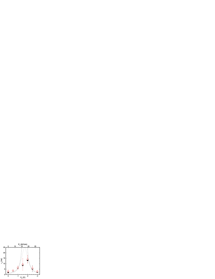
The fits of the temporal decay of by Eq. 15 yields the dependence of on and on the laser power shown in Fig. 8. The dashed and dotted lines show, for comparison, the calculated DP dephasing lifetime for out-of-plane and precessing spins in an homogeneous spin ensemble.Hernández-Mínguez et al. (2012) As expected, has a maximum at kV/cm, where it fulfills , and decreases as the electric field moves away from SO-compensation. Finally, we would like to remark that, for kV/cm, lies below , as expected from the behavior of the time-integrated discussed in Fig. 5.
V Summary
We have shown that the application of a transverse electric field allows the transport of out-of-plane spin polarized electrons in an intrinsic GaAs (111) QW over distances exceeding 10 m. We attribute the long transport distance to the compensation of the in-plane Dresselhaus SO-interaction by the Rashba one generated by the electric field, which cancels the precession of the spin vector around the SO-field during the radial expansion of the photogenerated e-h ensemble. At SO-compensation, the main mechanism limiting the transport distance of the spin-polarized electrons is their recombination with holes, which takes place in typically a few nanoseconds. The favorable properties for spin transport of GaAs (111) QWs make them an excellent platform for further studies of the spin dynamics, as well as for spintronics applications.
Acknowledgements
We thank Dr. Ramsteiner for useful discussions as well as M. Höricke and S. Rauwerdink for MBE growth and sample processing. We gratefully acknowledge financial support from the German DFG (priority program SSP1285).
References
- Awschalom et al. (2002) D. Awschalom, D. Loss, and N. Samarth, Semiconductor spintronics and quantum computation, Nanoscience and technology. (Springer, Berlin ; New York, 2002).
- Zutic et al. (2004) I. Zutic, J. Fabian, and S. D. Sarma, Rev. Mod. Phys. 76, 323 (2004).
- D’yakonov and Perel’ (1972) M. I. D’yakonov and V. I. Perel’, Sov. Phys. Solid State 13, 3023 (1972).
- D’yakonov and Kachorovskii (1986) M. I. D’yakonov and V. Y. Y. Kachorovskii, Sov. Phys. Semicond. 20, 110 (1986).
- Dresselhaus (1955) G. Dresselhaus, Phys. Rev. 100, 580 (1955).
- Christensen and Cardona (1984) N. Christensen and M. Cardona, Solid State Communications 51, 491 (1984).
- Cardona et al. (1988) M. Cardona, N. E. Christensen, and G. Fasol, Phys. Rev. B 38, 1806 (1988).
- Eppenga and Schuurmans (1988) R. Eppenga and M. F. H. Schuurmans, Phys. Rev. B 37, 10923 (1988).
- Bychkov and Rashba (1984) Y. A. Bychkov and E. I. Rashba, J. Phys. C 17, 6039 (1984).
- Winkler (2003) R. Winkler, Spin-Orbit Coupling Effects in Two-Dimensional Electron and Hole Systems, Vol. 191 (Springer, Berlin, 2003).
- Cartoixa et al. (2005) X. Cartoixa, D. Z.-Y. Ting, and Y.-C. Chang, Phys. Rev. B 71, 045313 (2005).
- Vurgaftman and Meyer (2005) I. Vurgaftman and J. R. Meyer, J. Appl. Phys. 97, 053707 (2005).
- Balocchi et al. (2011) A. Balocchi, Q. H. Duong, P. Renucci, B. L. Liu, C. Fontaine, T. Amand, D. Lagarde, and X. Marie, Phys Rev. Lett. 107, 136604 (2011).
- Biermann et al. (2012) K. Biermann, A. Hernández-Mínguez, R. Hey, and P. V. Santos, J. Appl. Phys. 112, 083913 (2012).
- Hernández-Mínguez et al. (2012) A. Hernández-Mínguez, K. Biermann, R. Hey, and P. V. Santos, Phys. Rev. Lett. 109, 266602 (2012).
- Sun et al. (2010) B. Y. Sun, P. Zhang, and M. W. Wu, J. Appl. Phys. 108, 093709 (2010).
- Wang et al. (2013a) G. Wang, A. Balocchi, D. Lagarde, C. R. Zhu, T. Amand, P. Renucci, Z. W. Shi, W. X. Wang, B. L. Liu, and X. Marie, App. Phys. Lett. 102, 242408 (2013a).
- Balocchi et al. (2013) A. Balocchi, T. Amand, G. Wang, B. L. Liu, P. Renucci, Q. H. Duong, and X. Marie, New. J. Phys. 15, 095016 (2013).
- Hernández-Mínguez et al. (2014) A. Hernández-Mínguez, K. Biermann, R. Hey, and P. V. Santos, Phys. Status Solidi B 251, 1736 (2014).
- Kikkawa and Awschalom (1999) J. M. Kikkawa and D. D. Awschalom, Nature 397, 139 (1999).
- Crooker et al. (2005) S. A. Crooker, . X. L. M. Furis, C. Adelmann, D. L. Smith, C. J. Palmström, and P. A. Crowell, Science 309, 2191 (2005).
- Yu et al. (2009) H.-L. Yu, X.-M. Zhang, P.-F. Wang, H.-Q. Ni, Z.-C. Niu, and T. Lai, App. Phys. Lett. 94, 202109 (2009).
- Quast et al. (2009) J.-H. Quast, G. V. Astakhov, W. Ossau, L. W. Molenkamp, J. Heinrich, S. Höfling, and A. Forchel, Phys. Rev. B 79, 245207 (2009).
- Quast et al. (2013) J.-H. Quast, T. Henn, T. Kiessling, W. Ossau, L. W. Molenkamp, D. Reuter, and A. D. Wieck, Phys. Rev. B 87, 205203 (2013).
- Weber et al. (2011) C. P. Weber, C. A. Benko, and S. C. Hiew, J. App. Phys. 109, 106101 (2011).
- Henn et al. (2013) T. Henn, T. Kiessling, W. Ossau, L. W. Molenkamp, D. Reuter, and A. D. Wieck, Phys. Rev. B 88, 195202 (2013).
- Cameron et al. (1996) A. R. Cameron, P. Riblet, and A. Miller, Phys. Rev. Lett. 76, 4793 (1996).
- Eldridge et al. (2008) P. S. Eldridge, W. J. H. Leyland, P. G. Lagoudakis, O. Z. Karimov, M. Henini, D. Taylor, R. T. Phillips, and R. T. Harley, Phys. Rev. B 77, 125344 (2008).
- Zhao et al. (2009) H. Zhao, M. Mower, and G. Vignale, Phys. Rev. B 79, 115321 (2009).
- Hu et al. (2011) C. Hu, H. Ye, G. Wang, H. Tian, W. Wang, W. Wang, B. Liu, and X. Marie, Nanoscale Res. Lett. 6, 149 (2011).
- Henn et al. (2014) T. Henn, J.-H. Quast, T. Kiessling, W. Ossau, L. W. Molenkamp, D. Reuter, A. D. Wieck, K. Biermann, and P. V. Santos, Phys. Status Solidi B 251, 1839 (2014).
- Weber et al. (2005) C. P. Weber, N. Gedik, J. E. Moore, J. Orenstein, J. Stephens, and D. D. Awschalom, Nature 437, 1330 (2005).
- Carter et al. (2006) S. G. Carter, Z. Chen, and S. T. Cundiff, Phys. Rev. Lett. 97, 136602 (2006).
- Völkl et al. (2011) R. Völkl, M. Griesbeck, S. A. Tarasenko, D. Schuh, W. Wegscheider, C. Schüller, and T. Korn, Phys. Rev. B 83, 241306 (2011).
- Völkl et al. (2014) R. Völkl, M. Schwemmer, M. Griesbeck, S. A. Tarasenko, D. Schuh, W. Wegscheider, C. Schüller, and T. Korn, Phys. Rev. B 89, 075424 (2014).
- Altmann et al. (2014) P. Altmann, M. P. Walser, C. Reichl, W. Wegscheider, and G. Salis, Phys. Rev. B 90, 201306(R) (2014).
- Kohda et al. (2015) M. Kohda, P. Altmann, D. Schuh, S. D. Ganichev, W. Wegscheider, and Salis, App. Phys. Lett. 107, 172402 (2015).
- Altmann et al. (2015) P. Altmann, M. Kohda, C. Reichl, W. Wegscheider, and G. Salis, Phys. Rev. B 92, 235304 (2015).
- D’Amico and Vignale (2001) I. D’Amico and G. Vignale, Europhys. Lett. 55, 566 (2001).
- Wang et al. (2013b) G. Wang, B. L. Liu, A. Balocchi, P. Renucci, C. R. Zhu, T. Amand, C. Fontaine, and X. Marie, Nature Com 4, 2372 (2013b).
- Damen et al. (1991) T. C. Damen, L. Viña, J. E. Cunningham, J. Shah, and L. J. Sham, Phys. Rev. Lett. 67, 3432 (1991).
- Hilton and Tang (2002) D. J. Hilton and C. L. Tang, Phys. Rev. Lett. 89, 146601 (2002).
- Remeika et al. (2009) M. Remeika, J. C. Graves, A. T. Hammack, A. D. Meyertholen, M. M. Fogler, L. Butov, M. Hanson, and A. C. Gossard, Phys. Rev. Lett. 102, 186803 (2009).
- Meier and Zakharchenya (1984) F. Meier and B. P. Zakharchenya, Optical orientation, edited by V. M. Agranovich and A. A. Maradudin, Modern problems in condensed matter physics No. 8 (North-Holland, Amsterdam, The Netherlands, 1984).
- Froltsov (2001) V. A. Froltsov, Phys. Rev. B 64, 045311 (2001).
- Stanescu and Galitski (2007) T. D. Stanescu and V. Galitski, Phys. Rev. B 75, 125307 (2007).
- Yang et al. (2010) L. Yang, J. Orenstein, and D.-H. Lee, Phys. Rev. B 82, 155324 (2010).
- Poshakinskiy and Tarasenko (2015) A. V. Poshakinskiy and S. A. Tarasenko, Phys. Rev. B 92, 045308 (2015).
- Bernevig et al. (2006) B. A. Bernevig, J. Orenstein, and S.-C. Zhang, Phys. Rev. Lett. 97, 236601 (2006).
- Koralek et al. (2009) J. D. Koralek, C. P. Weber, J. Orenstein, B. A. Bernevig, S.-C. Zhang, S. Mack, and D. D. Awschalom, Nature 458, 610 (2009).
- Walser et al. (2012) M. P. Walser, C. Reichl, W. Wegscheider, and G. Salis, Nat. Phys. 8, 757 (2012).
- Note (1) Although a Bessel function is a more appropriate solution for a radially symmetric differential equation than a harmonic oscillation, both functions behave similar for .
- Note (2) The repulsive forces at must be because of the radial symmetry of the carrier density. Due its gaussian shape, the carrier concentration is the largest at the center and decays radially towards zero. Therefore, must initially increase with until reaching a maximum around , and then decay towards .
- Salis et al. (2014) G. Salis, M. P. Walser, P. Altmann, C. Reichl, and W. Wegscheider, Phys. Rev. B 89, 045304 (2014).