Two-dimensional nodal-loop half metal in monolayer MnN
Abstract
Two-dimensional (2D) materials with nodal-loop band crossing have been attracting great research interest. However, it remains a challenge to find 2D nodal loops that are robust against spin-orbit coupling (SOC) and realized in magnetic states. Here, based on first-principles calculations and theoretical analysis, we predict that monolayer MnN is a 2D nodal-loop half metal with fully spin polarized nodal loops. We show that monolayer MnN has a ferromagnetic ground state with out-of-plane magnetization. Its band structure shows half metallicity with three low-energy bands belonging to the same spin channel. The crossing between these bands forms two concentric nodal loops centered around the point near the Fermi level. Remarkably, the nodal loops and their spin polarization are robust under SOC, due to the protection of a mirror symmetry. We construct an effective model to characterize the fully polarized emergent nodal-loop fermions. We also find that a uniaxial strain can induce a loop transformation from a localized single loop circling around to a pair of extended loops penetrating the Brillouin zone.
I Introduction
Two-dimensional (2D) materials have been attracting tremendous interest since the discovery of graphene Novoselov et al. (2004); Butler et al. (2013); Bhimanapati et al. (2015); Novoselov et al. (2016). Many remarkable physical properties of graphene are connect to its topological band structure, namely, the conduction and valence bands of graphene linearly cross at two isolated Fermi points in the Brillouin zone (BZ), which makes the low-energy electrons resemble 2D massless Dirac fermions Castro Neto et al. (2009). With the rapid advance in experimental techniques, many new 2D materials have been fabricated in recent years Butler et al. (2013); Bhimanapati et al. (2015); Novoselov et al. (2016), and inspired by graphene, there is great interest to explore 2D materials with nontrivial band topology.
In 2D, topological band crossings can take the form of 0D nodal points and also 1D nodal loops. Several 2D nodal-loop materials have been proposed in theory Jin et al. (2017); Li et al. (2018); Zhou et al. (2018); Zhong et al. (2019); Wu (2), and nodal loops in monolayer Cu2Si and monolayer CuSe have been confirmed in recent experiments Feng et al. (2017); Gao et al. (2018). Compared to nodal points, the condition for stabilizing nodal loops in 2D is typically more stringent.
Two factors related to electron spin play important roles in the stability of nodal loops. The first is the spin-orbit coupling (SOC). Without SOC, spin is a dummy degree of freedom (for nonmagnetic systems), which only introduces a trivial double degeneracy, and the electrons can be regarded as spinless fermions when analyzing the symmetry/topology protection. However, when SOC is included, spin has to be explicitly considered. Particularly, the symmetry groups for electronic states need to be described by double valued representations rather than single valued ones. Because the number of double valued representations for a group is generally less than their single valued counterparts, a band crossing protected in the absence of SOC is usually destroyed when SOC is turned on. For example, the Dirac points in graphene and most other 2D materials are unstable under SOC Kane and Mele (2005). To have a real Dirac point in 2D, a condition involving certain nonsymmorphic symmetries was proposed Young and Kane (2015), and such spin-orbit Dirac point was recently found in monolayer HfGeTe family materials Guan et al. (2017). Similarly, most nodal loops in 2D proposed so far are vulnerable against SOC. For example, the nodal loops in monolayer Cu2Si and monolayer CuSe are protected by mirror symmetry in the absence of SOC, but they are removed when SOC is included Feng et al. (2017); Gao et al. (2018). Hence, to find a 2D material with nodal loop robust against SOC is a much more difficult task.
The second factor is the spin polarization associated with magnetic ordering. 2D magnetic materials with high spin polarization are much desired also from the application perspective, because these materials are useful for compact spintronic devices. Nevertheless, magnetic orders break the time reversal symmetry, which also makes the protection of nodal loops more challenging, especially in the presence of SOC. A few 2D magnetic nodal-loop materials were reported till now, including Na2CrBi trilayer Niu et al. (2017), monolayer CrAs2 Wang et al. (2018a), and single-layer GdAg2 Feng et al. (2019). However, in these examples, both spin-up and spin-down states coexist near the Fermi level, which decreases the net spin polarization for the current carriers. It is thus most desirable to have nodal loops formed in a single spin channel around the Fermi level, i.e., to realize a nodal-loop half metal state. In 3D, such a state was recently predicted for Li3(FeO3)2 Chen et al. (2019), which hosts two fully spin-polarized nodal loops. In 2D, such a nodal-loop half metal has yet to be discovered.
In this work, based on first-principles calculations, we reveal monolayer MnN as the first example of a 2D nodal-loop half metal, with fully spin-polarized nodal loops robust against SOC. A previous work by Xu and Zhu Xu and Zhu (2018) has demonstrated that monolayer MnN enjoys good dynamic and thermal stability, and it has a rigid ferromagnetic ordering. Here, we show that the electronic band structure of monolayer MnN features two fully spin-polarized nodal loops near the Fermi level. The two loops are centered around the point, protected by a mirror symmetry, and more importantly, robust against SOC. We construct an effective model to describe the low-energy electronic states around the nodal loops. Furthermore, we find that moderate uniaxial strain can transform the outer nodal loop into two nodal loops both traversing the BZ. This corresponds to a transition in the loop winding topology, characterized by a index. Our work reveals a promising material platform for exploring the fundamental physics of fully spin-polarized 2D nodal-loop fermions, which also holds great potential for nanoscale spintronics applications.
II Computational Method
Our first-principles calculations were based on the density functional theory (DFT), as implemented in the Vienna ab-initio simulation package (VASP) Kresse and Hafner (1993); Kresse (1996). The interaction between electrons and ions was modeled using the projector augmented wave method Blöchl (1994). The generalized gradient approximation (GGA) parameterized by Perdew, Burke, and Ernzerhof (PBE) was adopted for the exchange-correlation functional Perdew et al. (1996). To account for the important correlation effect associated with the Mn- orbitals, we included the Hubbard correction via the PBE method Dudarev et al. (1998). Several Hubbard values were tested, which showed qualitatively similar results. Below, we shall present the results with the value set as 5 eV. A vacuum space of Å thickness was used to avoid artificial interactions between periodic images. The energy cutoff was set to be eV for the plane-wave basis. The Monkhorst-Pack -mesh Monkhorst and Pack (1976) with size was adopted for the BZ sampling. The lattice parameters and the ionic positions were fully optimized until the residual force on each atom was less than eV/Å. The energy convergence criterion was set to be eV.
III Structure and Elastic property
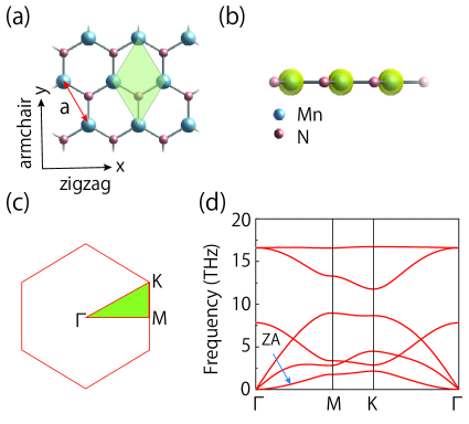
The lattice structure for monolayer MnN is shown in Fig. 1(a) and 1(b). The material is completely flat with a single atomic layer like graphene. It takes a 2D honeycomb lattice, with Mn and N occupying the A and B sites respectively. The space group is , and the point group is . The important symmetry here is the horizontal mirror , which will play an important role when discussing the band structure. A primitive unit cell contains one Mn atom and one N atom. From our calculation, the equilibrium lattice constant is Å for the fully relaxed structure, which is in good agreement with the previous work Xu and Zhu (2018). The obtained equilibrium Mn-N bond length is Å.
The dynamical stability of monolayer MnN can be inferred from its phonon spectrum. As shown in Fig. 1(d), there is no imaginary frequency phonon mode throughout the BZ, indicating that the material is dynamically stable. Approaching the point, there are two linearly dispersing in-plane acoustic branches, and there is also a quadratic out-of-plane acoustic (ZA) branch. The appearance of the quadratic ZA branch is a characteristic feature of 2D materials Zabel (2001); Zhu et al. (2014); Carrete et al. (2016). The sound speed for the longitudinal acoustic phonons in monolayer MnN ( km/s) is smaller than that of graphene ( km/s) Kaasbjerg et al. (2012) as well as blue phosphorene ( km/s) Zhu and Tománek (2014), indicating that monolayer MnN should have relatively small in-plane stiffness, as we show below.
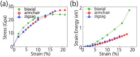
Next we examine the elastic properties. The calculated strain-stress and strain-energy curves are plotted in Fig. 2. One can observe that monolayer MnN can sustain a large biaxial strain up to , while the critical uniaxial strain can be for the armchair direction and for the zigzag direction. These values are comparable to other 2D materials such as graphene Lee et al. (2008), MoS2 Castellanos-Gomez et al. (2012); Bertolazzi et al. (2011), phosphorene Peng et al. (2014), and C2N Guan et al. (2015). Monolayer MnN remains within the linear elastic regime until about biaxial strain and uniaxial strain. For small deformations, the elastic property of D materials is usually characterized by the in-plane stiffness constant, defined as
| (1) |
where is the equilibrium area of the unit cell, is the strain energy (i.e., the energy difference between the strained and unstrained systems), and is the in-plane uniaxial strain. From the stain-energy curve in Fig. 2(b), the typical quadratic dependence can be observed at small deformations. The obtained stiffness constants are N/m and N/m for strains along the armchair and the zigzag directions, respectively. These values are smaller than other typical 2D materials such as graphene ( N/m) Lee et al. (2008), MoS2 ( N/m) Peng and De (2013), and BN ( N/m) Topsakal et al. (2010), and are similar to C2N ( N/m) Guan et al. (2015) and Mg2C ( N/m) Wang et al. (2018b). This indicates that monolayer MnN is quite flexible, which will facilitate the strain engineering of its physical properties.
IV Magnetic property
The transition metal elements like Mn often carry magnetic moments due to their partially filled shell. The materials containing Mn hence often exhibit magnetic ordering, which is the case for monolayer MnN. In our calculation, we compare the energies of different magnetic configurations: nonmagnetic (NM), ferromagnetic (FM), and antiferromagnetic (AFM), to determine the ground state of monolayer MnN. It is found that the FM state is energetically favored, while the NM sate and the AFM state are respectively and eV higher than the FM state per unit cell. In the FM state, the magnetic moment is mainly distributed on the Mn sites [see Fig. 1(b)], with per Mn atom.
To pin down the easy axis for the FM state, the magnetic anisotropy energy calculation was performed by scanning different orientations for the magnetic moment with SOC included. The result shows that the out-of-plane (along ) configuration is most energetically favorable, which is about 0.4 meV lower in energy than the in-plane configuration. Thus, the ground state magnetic configuration for monolayer MnN is an FM state with magnetization along the out-of-plane direction.
We have also estimated the Curie temperature for the FM state, by using the Monte Carlo simulation based on a classical Heisenberg-like spin model Evans et al. (2014):
| (2) |
where superscripts and label the Mn sites, indicates nearest neighboring sites, is the FM exchange coupling strength, and represents the magnetic anisotropy strength. The calculated Curie temperature for monolayer MnN is around 200 K, which is comparable with other 2D ferromagnetic materials discovered to date, such as Cr2Ge2Te6 atomic layers (66 K) Gong et al. (2017), transition metal halides (23-128 K) Huang et al. (2017); Kulish and Huang (2017), and Fe3GeTe2 (130 K) Fei et al. (2018).
V 2D Nodal-loop half metal
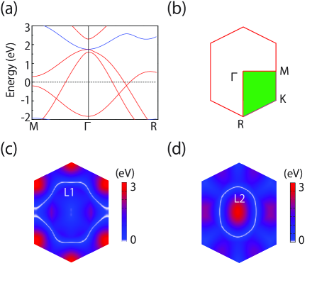
The most interesting property of monolayer MnN lies in its electronic band structure. Let’s first examine the band structure in the absence of SOC, as shown in Fig. 3(a). Two salient features can be observed. First, the ground state of monolayer MnN is a half metal. The bands for majority spin (denoted as spin up) display a metallic behavior, whereas the bands for minority spin (denoted as spin down) have a large energy gap about eV. The low-energy electrons near the Fermi level are therefore fully spin polarized. Second, several linear band crossings are observed for the majority spin bands close to the Fermi level. Among these low-energy bands, one is electron-like (labeled as band) and the other two are hole-like (labeled as and bands). From orbital projections in Fig. 3(b), we find that the and bands are mainly contributed by the Mn (, ) orbitals, while the band is mainly from the N orbital. The band crossings occur between the band and the other two bands. A careful scan of the band structure shows that these crossing points are not isolated, instead, they actually belong to two concentric nodal loops centered around the point, as shown in Fig. 3(e) and 3(f). We label the outer loop and the inner loop as and , respectively.
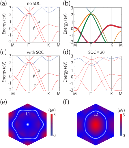
Remarkably, the two nodal loops persist when SOC is turned on. Figure 3(c) shows the band structure with SOC included. The result is similar to that in Fig. 3(a). To show that the nodal loops are indeed preserved under SOC, we artificially increase the SOC strength by 20 times in the DFT calculation, and plot the resulting band structure in Fig. 3(d). It clearly shows that the crossings are robust against SOC. What protects the nodal loops? By analyzing the symmetry properties of the three bands, we find that the two loops are protected by the mirror symmetry . Because the ground state magnetization is along the out-of-plane direction, is preserved in the FM state. The two hole-like bands and have the eigenvalue , whereas the electron-like band has the opposite eigenvalue . Therefore, band must cross and bands without hybridization, and the resulting two loops are protected as long as the mirror symmetry is maintained. Furthermore, because of the symmetry, the eigenstates must be spin polarized along , i.e., the spin-up and spin-down bands do not hybridize and each band remains fully spin polarized. Thus, monolayer MnN indeed provides a 2D nodal-loop half metal with fully spin-polarized nodal loops robust under SOC.
A nodal loop can be classified as type-I, type-II Li et al. (2017), or hybrid type Li et al. (2017); Zhang et al. (2018), based on the type of dispersion around the loop. A type-I (type-II) nodal loop consists solely of type-I (type-II) nodal points, while a hybrid loop consists of both types Li et al. (2017); Zhang et al. (2018). The two nodal loops in monolayer MnN belong to type-I, because they each is formed by the crossing between an electron-like band and a hole-like band.
To characterize the emergent nodal-loop fermions, we construct an effective model for the low-energy band structure. We choose the three states at the point as the basis. We first consider the case without SOC. The state of the band corresponds to the irreducible representation for the point group, while the two degenerate states of and bands correspond to the representation. The model should respect the following symmetries: the threefold rotation , the twofold rotation , and . Expanding up to the quadratic order, we find that the effective Hamiltonian takes the form of
| (3) |
where , , , and are real valued parameters which can be obtained from fitting the DFT band structure. Note that the matrix element between the () and bands vanishes identically, because the two bands have opposite eigenvalues. Including SOC gives additional contribution, which can be treated as a perturbation due the relatively weak SOC strength. We find that the SOC term expanded to leading order takes the following form
| (4) |
with some real valued parameter . Obviously, the SOC term does not affect the presence of the two nodal loops. Its main effect is that the degeneracy for the states is lifted. This effective model fits the DFT band structure very well (see the Supplemental Material sup ).
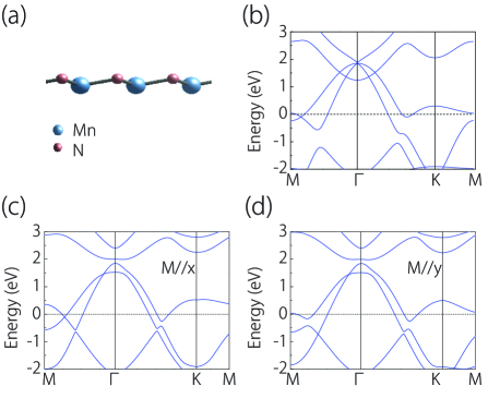
Breaking the mirror would generally destroy the nodal loops. This can be done, e.g., by artificially shifting the Mn atoms along relative to the N atoms, making a buckled honeycomb lattice [see Fig. 4(a)], or by orienting the magnetization direction in-plane. The corresponding band structure results in Fig. 4(b-d) show that the two loops are indeed gapped out when is broken.
VI Strain-induced nodal loop transformation
As discussed before, monolayer MnN enjoys good flexibility, hence its physical property should be readily tunable by strain. Here, we focus on the strain effect on the nodal loops. Since the two loops are protected by the horizontal mirror, they must be preserved under a variety of in-plane strains, such as the biaxial, uniaxial, and shear strains. Nevertheless, the shape of the loop may be changed by strain. For example, we consider the uniaxial strain along the armchair direction. Our result in Fig. 2(a) has shown that the critical strain is above . In Fig. 5(a), we show the band structure result for the 7% strain. One observes that while the loop remains a closed circle around the point, the crossing point on - for loop disappears, because the ordering between and bands at is switched. Accordingly, the loop is transformed from a localized loop circling around into two extended loops traversing the BZ, as shown in Fig. 5(c).
This transformation corresponds to a change in the loop winding topology defined on the BZ. In Ref. Li et al. (2017), it has been shown that loops can be characterized by its winding pattern in the BZ, captured by the fundamental homotopy group for the BZ. For 2D, the BZ is a two-torus. Since , the topology is characterized by two integers, each standing for the number of times the loop winds around the BZ in a particular direction. For the current case, the original without strain is characterized by an index , whereas the two loops after transformation [in Fig. 5(c)] are characterized by . Their topological distinction can be understood in the following way. The loop with index can be continuously deformed into a point and annihilate, whereas a single loop with index cannot. Similar transformation was recently reported in the 2D honeycomb borophene oxide Zhong et al. (2019). The monolayer MnN offers another platform for studying such interesting nodal loop transformation.
VII Discussion and Conclusion
We have a few remarks before closing. First, the finding reported here is significant, because it reveals the first example of a 2D nodal-loop half metal and the loops are robust against SOC. Almost all the nodal loops in 2D reported so far are not robust under SOC. 2D magnetic nodal-loop materials are also very rare. It is very fortunate that the nodal loop, its robustness against SOC, and half metallicity can occur in the same material. Besides, the material band structure has the following two additional advantages: (i) The low-energy bands for monolayer MnN are fairly simple and clean, without other extraneous bands; and (ii) the linear dispersion range is also quite large ( eV).
Second, as the nodal loops here are protected by symmetry, their existence is not sensitive to the first-principles calculation methods. For example, we have verified that qualitative features of the band structure remain the same when using the hybrid functional (HSE06) approach. The result can be found in the Supplemental Material sup .
Finally, we remark on several experimental aspects. It has been suggested that monolayer MnN can be synthesized by a spontaneous graphitic conversion from the ultrathin (111)-oriented cubic MnN in experiment Sorokin et al. (2014). The bottom-up approaches such as the molecular beam epitaxy (MBE) may also offer an alternative. It has been demonstrated that 2D monolayer CuSe with similar structure can be synthesized via the MBE approach with methane on the Cu(111) substrate Lin et al. (2017). The method is shown to be very versatile, and can be used as a general strategy for fabricating other 2D materials. The nodal loops can be directly imaged by using the angle-resolved photoemission spectroscopy (ARPES), as recently demonstrated for monolayer Cu2Si and CuSe Feng et al. (2017); Gao et al. (2018). The nodal loops may also produce features in the quasiparticle interference pattern which can be probed by the scanning tunneling microscopy experiment Zheng et al. (2016); Zhu et al. (2018). Techniques for applying strain on 2D materials have been well developed in recent years. For example, strain can be applied by using a beam bending apparatus Conley et al. (2013) or by using an atomic force microscope tip Lee et al. (2008). By using a stretchable substrate, controllable strains have been demonstrated for graphene Kim et al. (2009).
In conclusion, we have revealed monolayer MnN as a 2D nodal-loop half metal. We show that the material has good stability, can sustain large strains, and has excellent flexibility. The material has a FM ground state with an estimated Curie temperature about 200 K. Most interestingly, its band structure shows a half metal and features two concentric nodal loops near the Fermi level in a single spin channel. These nodal loops are protected by the mirror symmetry and are robust against SOC. We construct an effective model to characterize the emergent nodal-loop fermions. In addition, we find that a moderate uniaxial strain can generate an interesting loop topology transformation, from a single loop circling around to two loops traversing the BZ. Our work thus provides a promising platform to investigate the intriguing properties of nodal-loop fermions with time-reversal breaking. We hope that our theoretical work will facilitate the experimental studies on this new 2D material towards both fundamental discoveries and potential spintronics applications.
Acknowledgements.
The authors thank Hongming Weng, Ran Shen, and D. L. Deng for valuable discussions. This work is supported by the Singapore Ministry of Education Academic Research Fund Tier 2 (MOE2015-T2-2-144 and MOE2017-T2-2-108). We acknowledge computational support from the Texas Advanced Computing Center and National Supercomputing Centre Singapore.References
- Novoselov et al. (2004) K. S. Novoselov, A. K. Geim, S. V. Morozov, D. Jiang, Y. Zhang, S. V. Dubonos, I. V. Grigorieva, and A. A. Firsov, Science 306, 666 (2004).
- Butler et al. (2013) S. Z. Butler, S. M. Hollen, L. Cao, Y. Cui, J. A. Gupta, H. R. Gutiérrez, T. F. Heinz, S. S. Hong, J. Huang, A. F. Ismach, et al., ACS Nano 7, 2898 (2013).
- Bhimanapati et al. (2015) G. R. Bhimanapati, Z. Lin, V. Meunier, Y. Jung, J. Cha, S. Das, D. Xiao, Y. Son, M. S. Strano, V. R. Cooper, et al., ACS Nano 9, 11509 (2015).
- Novoselov et al. (2016) K. S. Novoselov, A. Mishchenko, A. Carvalho, and A. H. Castro Neto, Science 353, aac9439 (2016).
- Castro Neto et al. (2009) A. Castro Neto, F. Guinea, N. M. Peres, K. S. Novoselov, and A. K. Geim, Rev. Mod. Phys. 81, 109 (2009).
- Jin et al. (2017) Y.-J. Jin, R. Wang, J.-Z. Zhao, Y.-P. Du, C.-D. Zheng, L.-Y. Gan, J.-F. Liu, H. Xu, and S. Y. Tong, Nanoscale 9, 13112 (2017).
- Li et al. (2018) S. Li, Y. Liu, S.-S. Wang, Z.-M. Yu, S. Guan, X.-L. Sheng, Y. Yao, and S. A. Yang, Physical Review B 97, 045131 (2018).
- Zhou et al. (2018) P. Zhou, Z. Ma, and L. Sun, J. Mater. Chem. C 6, 1206 (2018).
- Zhong et al. (2019) C. Zhong, W. Wu, J. He, G. Ding, Y. Liu, D. Li, S. A. Yang, and G. Zhang, Nanoscale (2019).
- Wu (2) W. Wu, Y. Jiao, S. Li, X.-L. Sheng, Z.-M. Yu, and S. A. Yang, arXiv:1902.09283.
- Feng et al. (2017) B. Feng, B. Fu, S. Kasamatsu, S. Ito, P. Cheng, C.-C. Liu, Y. Feng, S. Wu, S. K. Mahatha, P. Sheverdyaeva, et al., Nat. Commun. 8, 1007 (2017).
- Gao et al. (2018) L. Gao, J.-T. Sun, J.-C. Lu, H. Li, K. Qian, S. Zhang, Y.-Y. Zhang, T. Qian, H. Ding, X. Lin, et al., Adv. Mater. 30, 1707055 (2018).
- Kane and Mele (2005) C. L. Kane and E. J. Mele, Phys. Rev. Lett. 95, 226801 (2005).
- Young and Kane (2015) S. M. Young and C. L. Kane, Phys. Rev. Lett. 115, 126803 (2015).
- Guan et al. (2017) S. Guan, Y. Liu, Z.-M. Yu, S.-S. Wang, Y. Yao, and S. A. Yang, Phys. Rev. Mater. 1, 054003 (2017).
- Niu et al. (2017) C. Niu, P. M. Buh, H. Zhang, G. Bihlmayer, D. Wortmann, S. Blügel, and Y. Mokrousov, arXiv:1703.05540 (2017).
- Wang et al. (2018a) B. Wang, H. Gao, Q. Lu, W. Xie, Y. Ge, Y.-H. Zhao, K. Zhang, and Y. Liu, Phys. Rev. B 98, 115164 (2018a).
- Feng et al. (2019) B. Feng, R.-W. Zhang, Y. Feng, B. Fu, S. Wu, K. Miyamoto, S. He, L. Chen, K. Wu, K. Shimada, et al., arXiv:1901.01429 (2019).
- Chen et al. (2019) C. Chen, Z.-M. Yu, S. Li, Z. Chen, X.-L. Sheng, and S. A. Yang, Phys. Rev. B 99, 075131 (2019).
- Xu and Zhu (2018) Z. Xu and H. Zhu, J. Phys. Chem. C 122, 14918 (2018).
- Kresse and Hafner (1993) G. Kresse and J. Hafner, Phys. Rev. B 47, 558 (1993).
- Kresse (1996) G. Kresse, Phys. Rev. B 54, 11169 (1996).
- Blöchl (1994) P. Blöchl, Phys. Rev. B 50, 17953 (1994).
- Perdew et al. (1996) J. P. Perdew, K. Burke, and M. Ernzerhof, Phys. Rev. Lett. 77, 3865 (1996).
- Dudarev et al. (1998) S. Dudarev, G. Botton, S. Savrasov, C. Humphreys, and A. Sutton, Phys. Rev. B 57, 1505 (1998).
- Monkhorst and Pack (1976) H. J. Monkhorst and J. D. Pack, Phys. Rev. B 13, 5188 (1976).
- Zabel (2001) H. Zabel, J. Phys. Condens. Matter. 13, 7679 (2001).
- Zhu et al. (2014) L. Zhu, G. Zhang, and B. Li, Phys. Rev. B 90, 214302 (2014).
- Carrete et al. (2016) J. Carrete, W. Li, L. Lindsay, D. A. Broido, L. J. Gallego, and N. Mingo, Mater. Res. Lett. 4, 204 (2016).
- Kaasbjerg et al. (2012) K. Kaasbjerg, K. S. Thygesen, and K. W. Jacobsen, Phys. Rev. B 85, 165440 (2012).
- Zhu and Tománek (2014) Z. Zhu and D. Tománek, Phys. Rev. Lett. 112, 176802 (2014).
- Lee et al. (2008) C. Lee, X. Wei, J. W. Kysar, and J. Hone, Science 321, 385 (2008).
- Castellanos-Gomez et al. (2012) A. Castellanos-Gomez, M. Poot, G. A. Steele, H. S. Van der Zant, N. Agraït, and G. Rubio-Bollinger, Nanoscale Res. Lett. 7, 233 (2012).
- Bertolazzi et al. (2011) S. Bertolazzi, J. Brivio, and A. Kis, ACS Nano 5, 9703 (2011).
- Peng et al. (2014) X. Peng, Q. Wei, and A. Copple, Phys. Rev. B 90, 085402 (2014).
- Guan et al. (2015) S. Guan, Y. Cheng, C. Liu, J. Han, Y. Lu, S. A. Yang, and Y. Yao, Applied Physics Letters 107, 231904 (2015).
- Peng and De (2013) Q. Peng and S. De, Phys. Chem. Chem. Phys. 15, 19427 (2013).
- Topsakal et al. (2010) M. Topsakal, S. Cahangirov, and S. Ciraci, Appl. Phys. Lett. 96, 091912 (2010).
- Wang et al. (2018b) S.-S. Wang, Y. Liu, Z.-M. Yu, X.-L. Sheng, L. Zhu, S. Guan, and S. A. Yang, Phys. Rev. Mater. 2, 104003 (2018b).
- Evans et al. (2014) R. F. Evans, W. J. Fan, P. Chureemart, T. A. Ostler, M. O. Ellis, and R. W. Chantrell, J. Phys. Condens. Matter. 26, 103202 (2014).
- Gong et al. (2017) C. Gong, L. Li, Z. Li, H. Ji, A. Stern, Y. Xia, T. Cao, W. Bao, C. Wang, Y. Wang, et al., Nature 546, 265 (2017).
- Huang et al. (2017) B. Huang, G. Clark, E. Navarro-Moratalla, D. R. Klein, R. Cheng, K. L. Seyler, D. Zhong, E. Schmidgall, M. A. McGuire, D. H. Cobden, et al., Nature 546, 270 (2017).
- Kulish and Huang (2017) V. V. Kulish and W. Huang, J. Mater. Chem. C 5, 8734 (2017).
- Fei et al. (2018) Z. Fei, B. Huang, P. Malinowski, W. Wang, T. Song, J. Sanchez, W. Yao, D. Xiao, X. Zhu, A. F. May, et al., Nat. Mater. 17, 778 (2018).
- Li et al. (2017) S. Li, Z.-M. Yu, Y. Liu, S. Guan, S.-S. Wang, X. Zhang, Y. Yao, and S. A. Yang, Phys. Rev. B 96, 081106 (2017).
- Zhang et al. (2018) X. Zhang, Z.-M. Yu, Y. Lu, X.-L. Sheng, H. Y. Yang, and S. A. Yang, Phys. Rev. B 97, 125143 (2018).
- (47) See Supplemental Material for the result obtained by hybrid functional approach and model fitting of the DFT band structure.
- Sorokin et al. (2014) P. B. Sorokin, A. G. Kvashnin, Z. Zhu, and D. Tomanek, Nano Lett. 14, 7126 (2014).
- Lin et al. (2017) X. Lin, J. Lu, Y. Shao, Y. Zhang, X. Wu, J. Pan, L. Gao, S. Zhu, K. Qian, Y. Zhang, et al., Nat. Mater. 16, 717 (2017).
- Zheng et al. (2016) H. Zheng, S.-Y. Xu, G. Bian, C. Guo, G. Chang, D. S. Sanchez, I. Belopolski, C.-C. Lee, S.-M. Huang, X. Zhang, et al., ACS Nano 10, 1378 (2016).
- Zhu et al. (2018) Z. Zhu, T.-R. Chang, C.-Y. Huang, H. Pan, X.-A. Nie, X.-Z. Wang, Z.-T. Jin, S.-Y. Xu, S.-M. Huang, D.-D. Guan, et al., Nat. Commun. 9, 4153 (2018).
- Conley et al. (2013) H. J. Conley, B. Wang, J. I. Ziegler, R. F. Haglund Jr, S. T. Pantelides, and K. I. Bolotin, Nano Lett. 13, 3626 (2013).
- Kim et al. (2009) K. S. Kim, Y. Zhao, H. Jang, S. Y. Lee, J. M. Kim, K. S. Kim, J.-H. Ahn, P. Kim, J.-Y. Choi, and B. H. Hong, Nature 457, 706 (2009).