Topologically Protected Photonic Modes in Composite Quantum Hall/Quantum Spin Hall Waveguides
Abstract
Photonic topological systems, the electromagnetic analog of the topological materials in condensed matter physics, create many opportunities to design optical devices with novel properties. We present an experimental realization of the bi-anisotropic meta waveguide photonic system replicating both quantum Hall (QH) and quantum spin-Hall (QSH) topological insulating phases. With careful design, a composite QH-QSH photonic topological material is created and experimentally shown to support reflection-free edgemodes, a heterogeneous topological structure that is unprecedented in condensed matter physics. The effective spin degree of freedom of such topologically protected modes determines their unique pathways through these systems, free from backscattering and able to travel around sharp corners. As an example of their novel properties, we experimentally demonstrate reflection-less photonic devices including a 2-port isolator, a unique 3-port topological device, and a full 4-port circulator based on composite QH and QSH structures.
I Introduction
During the past few years the realization of topological properties in photonic systems has paved the way for many novel applications and the creation of new states of light Haldane and Raghu (2008); Hasan and Kane (2010); Kraus et al. (2012); Raghu and Haldane (2008); Xie et al. (2018); Zhang (2017); Hou et al. (2018). Translating concepts from condensed matter physics into the optical domain has come from mapping electronic Hamiltonians, such as the Kane-Mele Hamiltonian, into photonic platforms Kane and Mele (2005); Raghu and Haldane (2008); Bernevig and Zhang (2006); Qi and Zhang (2011); Khanikaev and Shvets (2017). The photonic topological insulators (PTIs) possess similar topological properties to their electronic counterparts and allow light traveling through sharp corners without reflection Khanikaev and Shvets (2017). The observation of topologically protected surface waves (TPSWs) at microwave frequencies has been reported with biased magneto-optical photonic crystals with broken time-reversal invariance Wang et al. (2008, 2009); Skirlo et al. (2015); Longhi et al. (2015); Lu et al. (2016); Chen et al. (2017); Yang et al. (2019). Due to the difficulty of achieving strong magnetic effects at optical frequencies, a class of time-reversal invariant PTIs has been proposed: these include coupled resonators Hafezi et al. (2011, 2013); Gao et al. (2015); Mittal et al. (2014); Leykam et al. (2018) and bi-anisotropic meta-waveguide (BMW) PTIs Khanikaev et al. (2013); Chen et al. (2014); Cheng et al. (2016); Lai et al. (2016); Slobozhanyuk et al. (2016); Xiao et al. (2016); Yang et al. (2018). Recent studies revealed new designs of time-reversal-invariant PTIs based on emulating the quantum valley Hall (QVH) degree of freedom (DOF) in photonic systems Chen et al. (2018a); Noh et al. (2018); Yang et al. (2018); Gao et al. (2017); Gladstone et al. (2018); Chen et al. (2018b). Elegant Floquet topological photonic designs are also reported Fang et al. (2012a, b); Rechtsman et al. (2013a, b). In this manuscript, we focus on the experimental realization of quantum spin Hall (QSH) and quantum Hall (QH) PTIs in the context of the BMW structure. We believe that this is the first-ever realization of a time-reversal invariance breaking heterogeneous topological system based on two different microscopic Hamiltonians, in either the photonic or electronic domains.
The BMW approach to PTIs is unique in that it allows for integration of different photonic topological paradigms based on the same unperturbed structure. Here we present the first demonstration of a non-reciprocal BMW structure and integrate it with a reciprocal PTI domain to create a completely new class of PTI materials. In such composite BMW structures, a spin-momentum-locked TPSW can be spatially guided and filtered into desired channels at the junction points between different topological domains with high efficiency and free from backscattering Ma and Shvets (2017). We begin with the simulation and experimental studies of the QH-PTIs followed by integration of QH-QSH PTIs. We are the first to observe TPSWs at the interface of the QH-QSH composite system which effectively serves as a 2-port PTI isolator. We then introduce experimental demonstrations of more complex PTI structures, namely a unique topological Y-junction and a full 4-port circulator. Our realized circulator structure has unique advantages over conventional photonic designs where the guided modes are not topologically protected. The topologically trivial resonator-based circulators generally suffer from narrow bandwidth and are susceptible to backscattering due to impedance mismatches Wang and Fan (2005). An alternative QH-PTI based circulator faces challenges with respect to device size (tens of wavelengths) and the lack of a spin DOF Qiu et al. (2011). On the contrary, the topological protection and spin DOF ensure the propagation of guided waves in heterogeneous BMW-PTI systems is backscatter-free, with higher directivity Ma and Shvets (2017). The utilization of topologically protected waves allows for a broad spectral operating range, compact design, integration with other PTI paradigms and potential for high-power operation.
II QH-PTI System Design
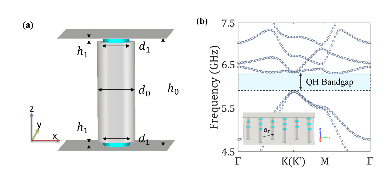
The BMW PTIs are based on an unperturbed structure of metallic rods arranged in a hexagonal lattice sandwiched between two metal plates Zandbergen and de Dood (2010); Bittner et al. (2010); Kuhl et al. (2010); Ma et al. (2015); Xiao et al. (2016); Ma and Shvets (2017). The structure dimensions are carefully designed to ensure the TE and TM modes are degenerate at the Dirac points with the same group velocity in the photonic band structure (PBS). The two orbital DOF are emulated with left/right-hand circular polarizations and the two synthetic spin DOF by the in-phase and out-of-phase linear combinations of the TE and TM modes at the Dirac point Ma and Shvets (2017). This mode crossing at the Dirac point can be destroyed by a broad range of spatial perturbations Ma et al. (2015); Cheng et al. (2016) thus creating a band gap, analogous to a bulk electronic insulator. In the present case, we create a QSH-PTI by adding an air gap between the rods and one plate, resulting in a bi-anisotropic response and an effective spin-orbit coupling (SOC) Xiao et al. (2016). Alternatively one can create a QH-PTI by placing magneto-optical materials in the gap. For QSH and QH domains, the spin-Chern numbers and a global Chern number , where is the spin state label and , are defined to quantify the topological properties of the upper and lower bands Ma and Shvets (2017). The spin-orbit coupling and time-reversal invariance breaking perturbations are defined as the overlap integrals of unperturbed modes’ field components within the perturbed volume in the QSH and QH regions, respectively. An interface separating two PTIs with different Chern numbers will support edge states that are spectrally localized in the bulk bandgap Ma et al. (2015); Khanikaev et al. (2013); Haldane and Raghu (2008). Both QSH and QVH types of BMW have been experimentally realized Xiao et al. (2016); Yang et al. (2018); Gao et al. (2017), leaving the experimental demonstration of the QH-BMW structure un-reported. Recent theoretical studies Ma and Shvets (2017) pave the way for realizing QH-PTIs in a BMW base by sandwiching biased gyromagnetic materials on top and bottom of the metallic rod (Fig. 1(a)). In contrast with Ma and Shvets (2017) which characterized the ferrites using a dielectric permittivity and a simplified permeability tensor, here the QH region is re-designed in order to incorporate realistic ferrite properties. Figure. 1 (a) and (b) show the bulk QH unit-cell model and its PBS, respectively. This band diagram is obtained with first-principles electromagnetic simulation using COMSOL Multiphysics. The ferrites are characterized by and the Polder permeability tensor Polder (1948) (see SM sup ). As shown in Fig. 1(b), under an external bias magnetic field of , a bandgap opens throughout the first Brillouin Zone, and matches closely with that of our existing QSH bulk structure Ma et al. (2015); Xiao et al. (2016). The degeneracy of TE and TM modes in the vicinity of the Dirac point is well-preserved as shown in Fig. 1 (b).
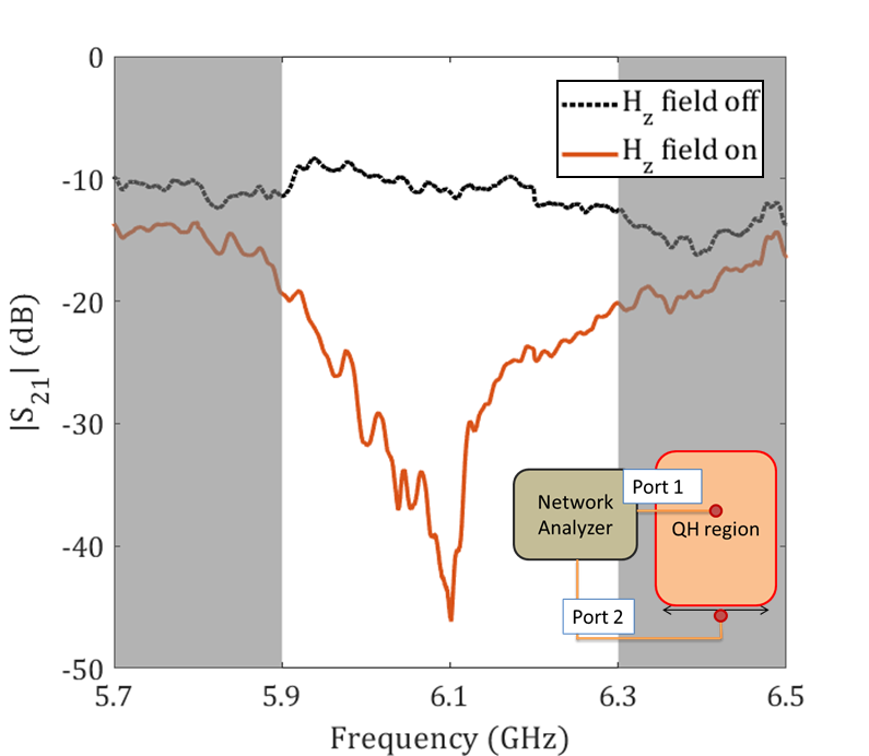
We next conduct transmission measurements through the proposed QH bulk structure. The gyromagnetic disks are made of commercial Yttrium Garnet ferrites which are magnetized along the axis using Nd-Fe-B permanent magnets located outside the structure on the top and bottom plates (see SM sup ). The QH region contains a ferrite-loaded lattice. Experimental results are presented as transmission S-parameters in Fig. 2. The inset of Fig. 2 shows the measurement method: the two ports of the Vector Network Analyzer (VNA) are connected to antennas at the center of a QH bulk structure and its perimeter. By switching on the H-field to magnetize the ferrites, we observed an averaged 20 dB decrease of transmission from port 1 to port 2 from 5.95 to 6.2 GHz which is slightly narrower compared to the photonic bandgap predicted in Fig. 1(b).
III Composite QH-QSH Systems
We next construct a heterogeneous PTI structure with two topological phases: QH and QSH PTIs. This composite PTI structure has an interface (Fig. S3) that will support topologically protected edgemodes (Fig. S2) in the operating bandwidth (the shaded area in Fig. 1(b)) inside the original bandgap frequencies for both QSH and QH bulk structures. The key requirement is to maintain the spin degeneracy of the modes in the composite structure, which allows edgemodes propagating without reflection Ma and Shvets (2017). Simulation results for a QH-QSH supercell structure (Fig. S2) show that in contrast to a QSH-QSH interface Xiao et al. (2016) where there are two edgemodes with opposite group velocities, a QH-QSH interface will only support one-way spin-locked TPSWs at the points.
The composite QH-QSH PTI structure has BMW rods in both regions (Fig. S3). We use the VNA to conduct 2-port measurements for edgemode transmission along the QH-QSH interface. In Fig. 3 (a)/(b), the left/right-going transmission for the two possible magnetic field biasing orientations is 35 dB higher than the transmission in the other direction in the joint band gap frequency range. These experimental results show that a QH-QSH interface can only support an edgemode with one synthetic spin direction. The backscattering-free property of an edgemode is also examined in Fig. S4. The inversion of applied H-field in the z-direction will invert the sign of the normalized bandgap for QH-PTIs Ma and Shvets (2017). With the QSH-PTIs unchanged, the supported edgemode at the QH-QSH interface will flip its spin, and more importantly invert its spin-locked propagation direction. The topologically protected edgemodes ensure strong suppression of the reflected flow of waves in the un-desired direction. The QH-QSH structure serves as an effective 2-port PTI isolator which can be turned on/off by external H-field (Fig. S7). The isolator’s allowed propagating direction can be switched in real-time by the inversion of the H-field.

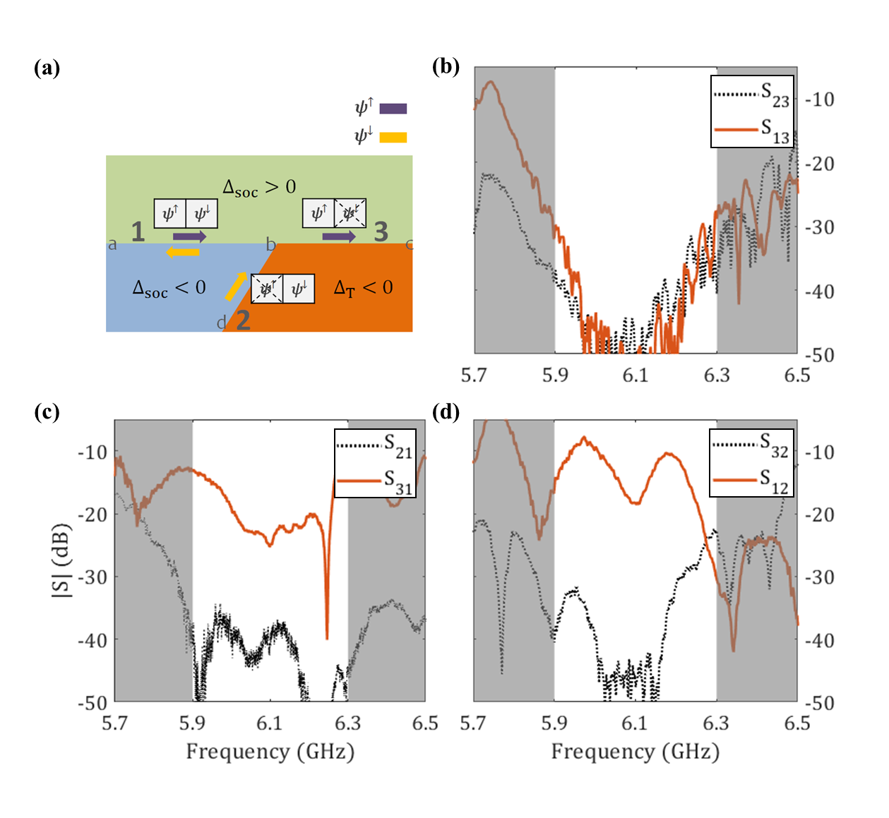
IV Topological Y-junction
With the experimental realizations of both QSH-QSH Xiao et al. (2016) and QH-QSH waveguides, we next propose a ‘Y-junction’ PTI structure which mixes three different topological phases (shown in Fig. S8 and schematically in Fig. 4(a)). The 3-port Y-junction possesses unique functions compared to more traditional devices, such as a 3-port circulator. With its spin DOF and propagation direction locked together, the edgemode transmission behavior inside the Y-junction can be predicted theoretically. For instance, an edgemode with either spin up () or down () can exist at interface ‘ab’, with their propagating direction restricted to right and left-going, respectively. Governed by the direction of the external H-field in the QH-region, a field will dictate that the Y-junction’s port 3 (2) becomes a forbidden source (receiver). To illustrate a forbidden source (receiver) experimentally, note the decrease of both and ( and ) from 5.9-6.3 GHz shown in Fig. 4(b) (Fig. 4(b) and (c)). Because the interface ‘bc’ can only support an up-spin mode , the signal injected at port 3 can not travel left to port 1 or 2. In Fig. 4(c) the amplitude of is 20 dB higher than , indicating that a right-going wave transmitted from port 1 will travel to port 3 instead of port 2. This choice of path is dictated by the fact that such an up-spin TPSW can only propagate along interface ‘bc’ but not ‘bd’. For similar reasons, a down-spin wave transmitted by port 2 will only go to port 1 as shown in Fig. 4(d). The ideal S-matrix of the topological Y-junction can be written as , which differs from a traditional 3-port circulator which creates a circulation. The functionality of a topological Y-junction is similar to the active quasi-circulator Mung and Chan (2019). Inversion of the H-field direction will turn port 3 (2) into a forbidden receiver (source), due to the change in propagating edgemode spin polarization at the two QH-QSH interfaces (observed but not shown here) Ma and Shvets (2017). The topological Y-junction will act as a building block for more sophisticated structures, such as the 4-port circulator. The demonstrated Y-junction can serve as a versatile platform for many novel photonic applications based on various combinations of topological domains. For example, one can construct a backscattering-free photonic combiner with a QSH region and two QH regions with opposite H-field directions that leads edgemodes from two paths to merge onto the same third path with no backscattering. Furthermore, an inversion of biasing H-fields in the QH domains will turn the photonic combiner into a spin filter that divides photons with different synthetic spins into different paths, effectively creating a Stern-Gerlach device for the spin DOF of light. Such junctions may find application in quantum communication, Boolean networks models, and photonic devices based on manipulating photons with different polarization states.
V Topological 4-port Circulator
Novel non-reciprocal structure designs, like isolators and circulators, have been proposed recently due to their important roles in photonic and microwave circuits Seif and Hafezi (2018); Fang et al. (2017); Shen et al. (2018); Ni et al. (2018); Jia et al. (2019); Fleury et al. (2014); Maayani et al. (2018); Khanikaev et al. (2015). After the experimental demonstration of the Y-junction structure, we are in position to integrate different PTIs into another practical structure, namely a 4-port circulator. In contrast to realizing optical circulators with only 2D gyromagnetic PTIs Wang and Fan (2005), here we report the experimental realization of the combined PTI system with different types of topological phases Ma and Shvets (2017); Khanikaev and Shvets (2017). Similar to the design in Ma and Shvets (2017), the realized 4-port BMW circulator consists of a center QH island and four surrounding QSH regions with alternating signs (Fig. 5). The directions of both QSH-QSH and QH-QSH waveguides are chosen to be in the directions for optimized edgemode propagation.
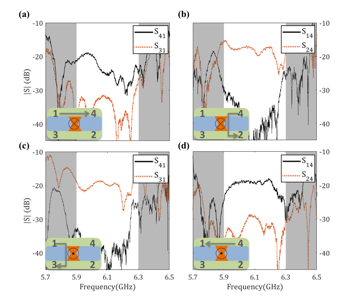
The operation of the BMW circulator is as follows. To start with, consider the trajectory of the up-spin edgemode which is launched from port 1 and propagating right along the QSH(green)-QSH(blue) waveguide (inset of Fig. 5(a)). When the edgemode arrives at the QSH-QH-QSH Y-junction, there exist two QH-QSH waveguides (‘red-blue’ and ‘red-green’) which support edgemodes with opposite spins. The topological nature of these modes will lead the wave to only one of the two QH-QSH waveguides, without backscattering Ma and Shvets (2017): at the first Y-junction, the spin up wave will merge on to the horizontal QH-QSH interface; at the second Y-junction, it will choose the QSH-QSH interface over the vertical QH-QSH interface because that QH-QSH interface does not support spin up edgemodes. As shown in Fig. 5(a), the measured transmission from port 1 to 4 () enjoys an averaged 15 dB boost compared to the competing vertical path (port 1 to 3) in the bulk band gap from 5.9 to 6.3 GHz. Combined with the other three guided edgemode paths, a clear circulation pattern is observed around the center QH-island.
The inversion of the direction will change the sign of of the QH region and further lead to the flip of spins of the propagating modes at all QH-QSH interfaces. Considering again the same up-spin TPSW launched from port 1: instead of choosing the horizontal QH-QSH interface, it will merge on to the vertical QH-QSH interface and finally flow to port 3. As shown in Fig. 5(c), (the transmission from port 1 to port 3) is now higher than . To conclude: we observed the change of circulation direction from counter-clockwise (Fig. 5 (a) and (b)) to clockwise (Fig. 5 (c) and (d)) controlled by the external H-field biasing direction on the QH BMW region. The isolation of the circulator design is 20 dB on average, the input power is +5 dBm limited only by the VNA, and the frequency range is 5.9-6.3 GHz which can be tuned by scaling the structural dimensions.
Note that the parallel QSH-QSH waveguides can have cross-coupling issues caused by the finite-size limitation of the structure (see SM sup ). The devices also face energy dissipation due to the finite line-width of the ferrite, and enhanced insertion loss due to imperfect coupling between the antenna and guided modes in the structure. Implementation of a rotating dipole source will enhance the power delivery by directly and efficiently exciting uni-directional edgemodes on the QSH-QSH interfaces Xiao et al. (2016).
In conclusion, we experimentally realized the first BMW-type bulk QH-PTI materials and created a bandgap that matches the QSH-PTI structure Xiao et al. (2016) while maintaining spin degeneracy. We then observed the appearance of a QH bandgap experimentally by applying external magnetic field to a ferrite-loaded BMW. We are the first to create a QH-QSH interface system and observe spin-momentum-locked guided waves whose propagation depends on the pseudo-spin of the excitation as well as the direction of the magnetization of the QH region. Based on this result, we proposed and realized several new reflection-less photonic devices, such as a 2-port isolator and a 3-port topological Y-junction, and observed guided edgemodes that followed spin-dependent paths expected from theoretical predictions. We constructed a 4-port BMW circulator and observed clear circulation of edgemodes, where the circulation direction is dictated by the magnetization direction of the ferrites. The ability to construct composite photonic systems with both QSH and QH phases offers more flexible ways to study new phenomena that are difficult to achieve in condensed matter systems.
Acknowledgements.
This work was supported by ONR under Grant Nos. N000141512134 and N000141912481, AFOSR COE Grant FA9550-15-1-0171, DOE under grant DESC 0018788, the National Science Foundation (NSF) under Grants No. DMR-1120923, No. PHY-1415547 and No. ECCS-1158644.References
- Haldane and Raghu (2008) F. D. M. Haldane and S. Raghu, Physical Review Letters 100, 013904 (2008).
- Hasan and Kane (2010) M. Z. Hasan and C. L. Kane, Reviews of Modern Physics 82, 3045 (2010).
- Kraus et al. (2012) Y. E. Kraus, Y. Lahini, Z. Ringel, M. Verbin, and O. Zilberberg, Physical Review Letters 109, 106402 (2012).
- Raghu and Haldane (2008) S. Raghu and F. D. M. Haldane, Physical Review A 78, 033834 (2008).
- Xie et al. (2018) B.-y. Xie, H.-F. Wang, X.-y. Zhu, M.-H. Lu, Z. D. Wang, and Y.-f. Chen, Optics Express 26, 24531 (2018).
- Zhang (2017) F. Zhang, Science 358, 1075 (2017).
- Hou et al. (2018) J. Hou, Z. Li, X.-W. Luo, Q. Gu, and C. Zhang, (2018), arXiv:1808.06972 .
- Kane and Mele (2005) C. L. Kane and E. J. Mele, Physical Review Letters 95, 226801 (2005).
- Bernevig and Zhang (2006) B. A. Bernevig and S.-C. Zhang, Physical Review Letters 96, 106802 (2006).
- Qi and Zhang (2011) X.-L. Qi and S.-C. Zhang, Reviews of Modern Physics 83, 1057 (2011).
- Khanikaev and Shvets (2017) A. B. Khanikaev and G. Shvets, Nature Photonics 11, 763 (2017).
- Wang et al. (2008) Z. Wang, Y. D. Chong, J. D. Joannopoulos, and M. Soljačić, Physical Review Letters 100, 013905 (2008).
- Wang et al. (2009) Z. Wang, Y. Chong, J. D. Joannopoulos, and M. Soljačić, Nature 461, 772 (2009).
- Skirlo et al. (2015) S. A. Skirlo, L. Lu, Y. Igarashi, Q. Yan, J. Joannopoulos, and M. Soljačić, Physical Review Letters 115, 253901 (2015).
- Longhi et al. (2015) S. Longhi, D. Gatti, and G. D. Valle, Scientific Reports 5, 13376 (2015).
- Lu et al. (2016) L. Lu, J. D. Joannopoulos, and M. Soljačić, Nature Physics 12, 626 (2016).
- Chen et al. (2017) Z.-G. Chen, J. Mei, X.-C. Sun, X. Zhang, J. Zhao, and Y. Wu, Physical Review A 95, 043827 (2017).
- Yang et al. (2019) B. Yang, H. Zhang, T. Wu, R. Dong, X. Yan, and X. Zhang, Physical Review B 99, 045307 (2019).
- Hafezi et al. (2011) M. Hafezi, E. A. Demler, M. D. Lukin, and J. M. Taylor, Nature Physics 7, 907 (2011).
- Hafezi et al. (2013) M. Hafezi, S. Mittal, J. Fan, A. Migdall, and J. M. Taylor, Nature Photonics 7, 1001 (2013).
- Gao et al. (2015) W. Gao, M. Lawrence, B. Yang, F. Liu, F. Fang, B. Béri, J. Li, and S. Zhang, Physical Review Letters 114, 037402 (2015).
- Mittal et al. (2014) S. Mittal, J. Fan, S. Faez, A. Migdall, J. M. Taylor, and M. Hafezi, Physical Review Letters 113, 087403 (2014).
- Leykam et al. (2018) D. Leykam, S. Mittal, M. Hafezi, and Y. D. Chong, Physical Review Letters 121, 023901 (2018).
- Khanikaev et al. (2013) A. B. Khanikaev, S. Hossein Mousavi, W.-K. Tse, M. Kargarian, A. H. MacDonald, and G. Shvets, Nature Materials 12, 233 (2013).
- Chen et al. (2014) W.-J. Chen, S.-J. Jiang, X.-D. Chen, B. Zhu, L. Zhou, J.-W. Dong, and C. T. Chan, Nature Communications 5, 5782 (2014).
- Cheng et al. (2016) X. Cheng, C. Jouvaud, X. Ni, S. Hossein Mousavi, A. Z. Genack, A. B. Khanikaev, S. H. Mousavi, A. Z. Genack, and A. B. Khanikaev, Nature Materials 15 (2016).
- Lai et al. (2016) K. Lai, T. Ma, X. Bo, S. Anlage, and G. Shvets, Scientific Reports 6, 28453 (2016).
- Slobozhanyuk et al. (2016) A. P. Slobozhanyuk, A. B. Khanikaev, D. S. Filonov, D. A. Smirnova, A. E. Miroshnichenko, and Y. S. Kivshar, Scientific Reports 6, 22270 (2016).
- Xiao et al. (2016) B. Xiao, K. Lai, Y. Yu, T. Ma, G. Shvets, and S. M. Anlage, Physical Review B 94, 195427 (2016).
- Yang et al. (2018) Y. Yang, Y. F. Xu, T. Xu, H.-X. Wang, J.-H. Jiang, X. Hu, and Z. H. Hang, Physical Review Letters 120, 217401 (2018).
- Chen et al. (2018a) X. D. Chen, W. M. Deng, J. C. Lu, and J. W. Dong, Physical Review B 97, 184201 (2018a).
- Noh et al. (2018) J. Noh, S. Huang, K. P. Chen, and M. C. Rechtsman, Physical Review Letters 120, 063902 (2018).
- Gao et al. (2017) F. Gao, H. Xue, Z. Yang, K. Lai, Y. Yu, X. Lin, Y. Chong, G. Shvets, and B. Zhang, Nature Physics 14, 140 (2017).
- Gladstone et al. (2018) R. G. Gladstone, M. Jung, and G. Shvets, (2018), arXiv:1809.02819 .
- Chen et al. (2018b) X.-D. Chen, F.-L. Shi, H. Liu, J.-C. Lu, W.-M. Deng, J.-Y. Dai, Q. Cheng, and J.-W. Dong, Physical Review Applied 10, 044002 (2018b).
- Fang et al. (2012a) K. Fang, Z. Yu, and S. Fan, Physical Review Letters 108, 153901 (2012a).
- Fang et al. (2012b) K. Fang, Z. Yu, and S. Fan, Nature Photonics 6, 782 (2012b).
- Rechtsman et al. (2013a) M. C. Rechtsman, J. M. Zeuner, A. Tünnermann, S. Nolte, M. Segev, and A. Szameit, Nature Photonics 7, 153 (2013a).
- Rechtsman et al. (2013b) M. C. Rechtsman, J. M. Zeuner, Y. Plotnik, Y. Lumer, D. Podolsky, F. Dreisow, S. Nolte, M. Segev, and A. Szameit, Nature 496, 196 (2013b).
- Ma and Shvets (2017) T. Ma and G. Shvets, Physical Review B 95, 165102 (2017).
- Wang and Fan (2005) Z. Wang and S. Fan, Optics Letters 30, 1989 (2005).
- Qiu et al. (2011) W. Qiu, Z. Wang, and M. Soljačić, Optics Express 19, 22248 (2011).
- Zandbergen and de Dood (2010) S. R. Zandbergen and M. J. A. de Dood, Physical Review Letters 104, 043903 (2010).
- Bittner et al. (2010) S. Bittner, B. Dietz, M. Miski-Oglu, P. Oria Iriarte, A. Richter, and F. Schäfer, Physical Review B 82, 014301 (2010).
- Kuhl et al. (2010) U. Kuhl, S. Barkhofen, T. Tudorovskiy, H.-J. Stöckmann, T. Hossain, L. de Forges de Parny, and F. Mortessagne, Physical Review B 82, 094308 (2010).
- Ma et al. (2015) T. Ma, A. B. Khanikaev, S. H. Mousavi, and G. Shvets, Physical Review Letters 114, 127401 (2015).
- Polder (1948) D. Polder, Phys. Rev. 73, 155 (1948).
- (48) .
- Mung and Chan (2019) S. W. Mung and W. S. Chan, IEEE Microwave Magazine 20, 55 (2019).
- Seif and Hafezi (2018) A. Seif and M. Hafezi, Nature Photonics 12, 60 (2018).
- Fang et al. (2017) K. Fang, J. Luo, A. Metelmann, M. H. Matheny, F. Marquardt, A. A. Clerk, and O. Painter, Nature Physics 13, 465 (2017).
- Shen et al. (2018) Z. Shen, Y.-L. Zhang, Y. Chen, F.-W. Sun, X.-B. Zou, G.-C. Guo, C.-L. Zou, and C.-H. Dong, Nature Communications 9, 1797 (2018).
- Ni et al. (2018) X. Ni, M. Weiner, A. Alù, and A. B. Khanikaev, Nature Materials 18 (2018), 10.1038/s41563-018-0252-9.
- Jia et al. (2019) H. Jia, R. Zhang, W. Gao, Q. Guo, B. Yang, J. Hu, Y. Bi, Y. Xiang, C. Liu, and S. Zhang, Science 363, 148 (2019).
- Fleury et al. (2014) R. Fleury, D. L. Sounas, C. F. Sieck, M. R. Haberman, and A. Alù, Science 343, 516 (2014).
- Maayani et al. (2018) S. Maayani, R. Dahan, Y. Kligerman, E. Moses, A. U. Hassan, H. Jing, F. Nori, D. N. Christodoulides, and T. Carmon, Nature 558, 569 (2018).
- Khanikaev et al. (2015) A. B. Khanikaev, R. Fleury, S. H. Mousavi, and A. Alù, Nature Communications 6 (2015), 10.1038/ncomms9260.