Orientation of hole quantum Hall nematic phases in an out-of-plane electric field
Abstract
We present observations of an anisotropic resistance state at Landau level filling factor in a two-dimensional hole system (2DHS), which occurs for certain values of hole density and average out-of-plane electric field . The 2DHS is induced by electric field effect in an undoped GaAs/AlGaAs quantum well, where front and back gates allow independent tuning of and , and hence the symmetry of the confining potential. For cm-2 and V/m, the magnetoresistance along greatly exceeds that along , suggesting the formation of a quantum Hall nematic or “stripe” phase. Reversing the sign of rotates the stripes by . We suggest this behavior may arise from the mixing of the hole Landau levels and a combination of the Rashba and Dresselhaus spin-orbit coupling effects.
I Introduction
High quality two-dimensional electron systems (2DESs) in perpendicular magnetic fields with half-filled Landau levels (LLs) display a rich variety of ground states arising from electron-electron interactions. In the lowest () LL, at half filling of the spin up (filling factor ) or spin down states (), a compressible Fermi liquid of composite fermions is observed Halperin et al. (1993); Du et al. (1993); Willett (1997). Here, , where is the magnetic field and is the carrier density. In the LL, at and , high quality 2DESs show an incompressible fractional quantized Hall (FQH) state Willett et al. (1987); Pan et al. (1999a). At half filling in the higher () LLs, the magnetoresistance can become highly anisotropic Lilly et al. (1999a); Du et al. (1999), suggesting a transition to a density-modulated “stripe” phase. Indeed, Hartree-Fock theory had predicted the existence of a unidirectional charge density wave state at half-filling of high LLs Koulakov et al. (1996); Fogler et al. (1996); Moessner and Chalker (1996). More recent theoretical work Fradkin and Kivelson (1999); Fradkin et al. (2000); Wexler and Dorsey (2001); Cooper et al. (2002); Fradkin et al. (2010) suggests the stripe phase probably lacks long-range translational order and is more similar to a nematic phase 111As well as the nematic, smectic and anisotropic crystal ground states are possible; see Q. Qian, J. Nakamura, S. Fallahi, G.C. Gardner, and M.J. Manfra, Nature Commun. 8, 1536 (2017) and references therein.. For GaAs-based 2DESs grown on the surface, in all but a few cases Zhu et al. (2002); Cooper et al. (2004); Liu et al. (2013); Pollanen et al. (2015) the stripes are found to align along the direction, so that the magnetoresistance along is much higher than along MacDonald and Fisher (2000). Despite much investigation, it is still not clear what symmetry breaking mechanism causes the stripes to align in this way Cooper et al. (2001); Willett et al. (2001a); Pollanen et al. (2015); Shi et al. (2016a, b, 2017). An externally applied symmetry breaking mechanism, such as an in-plane magnetic field Lilly et al. (1999b); Pan et al. (1999b); Xia et al. (2010); Jungwirth et al. (1999); Stanescu et al. (2000) or periodic potential modulation Mueed et al. (2016) can re-orient the stripes along . In the LL, the FQH and stripe phases are thought to be very close in energy Rezayi and Haldane (2000), and with an in-plane magnetic field the FQH states at and give way to an anisotropic state Lilly et al. (1999b); Pan et al. (1999b); Xia et al. (2010). Hydrostatic pressure can also bring about a transition from the and FQH states to a nematic phase Samkharadze et al. (2015); Schreiber et al. (2018).
Two-dimensional hole systems (2DHSs) show somewhat similar behavior to 2DESs Shayegan et al. (2000); Manfra et al. (2006, 2007); Takado et al. (2007); Koduvayur et al. (2011). However, the FQH states at and/or are often replaced by a stripe phase. This has been attributed to Landau level mixing caused by spin-orbit coupling Manfra et al. (2007) and/or hole-hole interactions, which become more prominent due to the large effective hole mass Shayegan et al. (2000).
In this paper we present observations of an anisotropic state in a 2DHS in a GaAs quantum well (QW) at , which we believe to be a nematic/stripe phase. Our 2DHS is completely undoped, and symmetric front and back gates give us freedom to vary independently the 2DHS density and the asymmetry of the confining potential Croxall et al. (2013); Marcellina et al. (2018). The anisotropic state occurs for a narrow range of densities at sufficiently low temperature. The orientation of the stripes is found to rotate by when the direction of the electric field perpendicular to the 2DHS plane is reversed. We suggest this behavior may arise from a combination of the Rashba and Dresselhaus spin-orbit coupling effects, as predicted in Ref. Sodemann and MacDonald, 2008.
II Methods
Our device, illustrated in Fig. 1(a), contains a 2DHS induced by electric-field effect in a 25-nm-wide GaAs QW between two 300-nm-wide Al0.33Ga0.67As barriers. The wafer is grown by molecular-beam epitaxy on the GaAs surface. The device design and fabrication procedure are similar to those described in Ref. Croxall et al., 2013.
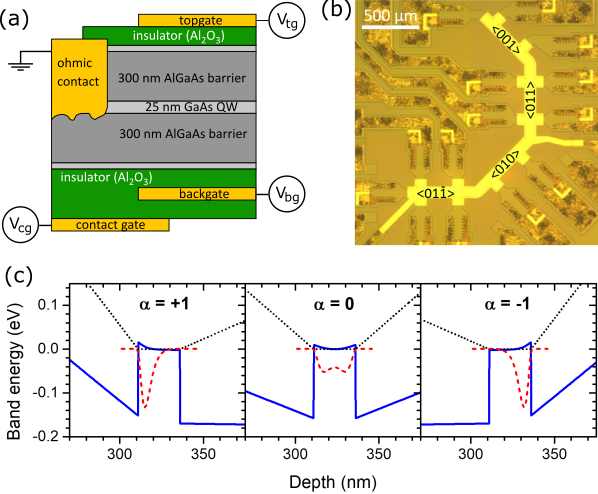
The semi-insulating substrate is completely removed, leaving a symmetric structure where the 2DHS density and the out-of-plane electric field can be varied independently using the voltages and applied to gates on the top and bottom surfaces of the device. We quantify the asymmetry of the confining potential by the dimensionless parameter , where is the electric field in the barrier above/below the QW. The electric field difference , and we denote the average electric field by . Figures 1(c) to 1(e) illustrate the valence band profile and 2DHS wavefunction for , and , calculated within an effective-mass approximation at zero magnetic field 222Figures 1(c) to (e) are calculated using the nextnano++ software, see https://www.nextnano.de/. For all the densities studied here, only the lowest subband of the QW is occupied Croxall et al. (2013). The 2DHS mobility depends on , , and direction, but is generally cm2/Vs.
The device geometry [Fig. 1(b)] allows measurement of the resistivity along the , , and directions. Measurements are carried out in a dilution refrigerator with a base temperature of 50 mK, using standard low-frequency ac techniques. Unless otherwise specified, the excitation current is 1.3 nA or less, to limit electron heating.
III Results
Our first experimental finding is that at , for certain densities and degrees of asymmetry, at low enough temperature, we see a large anisotropy in the 2DHS resistivity. Figure 2(a) shows the resistivity as a function of magnetic field in the and directions, at cm-2 when . At the resistivity in both directions is similar in magnitude. As becomes increasingly positive(negative) the peak in the () direction increases while the peak in the () direction diminishes. This leads to a large resistivity anisotropy, which is maximized for - [Figs. 2(b) and 2(c)]. As is further increased, the resistivity peak in the high resistance direction diminishes, so that isotropic behavior is restored for and signs of FQHSs appear at and [Figs. 2(d) and 2(e)]. We note that in the anisotropic state, where the resistivity shows a maximum in one direction, the resistance in the orthogonal direction does not show a minimum, as is often observed in quantum Hall nematic states. This may be because our device resembles a Hall bar, rather than a van der Pauw geometry. The van der Pauw geometry has been shown to accentuate the degree of anisotropy by current channelling effects Simon (1999); Willett et al. (2001b).
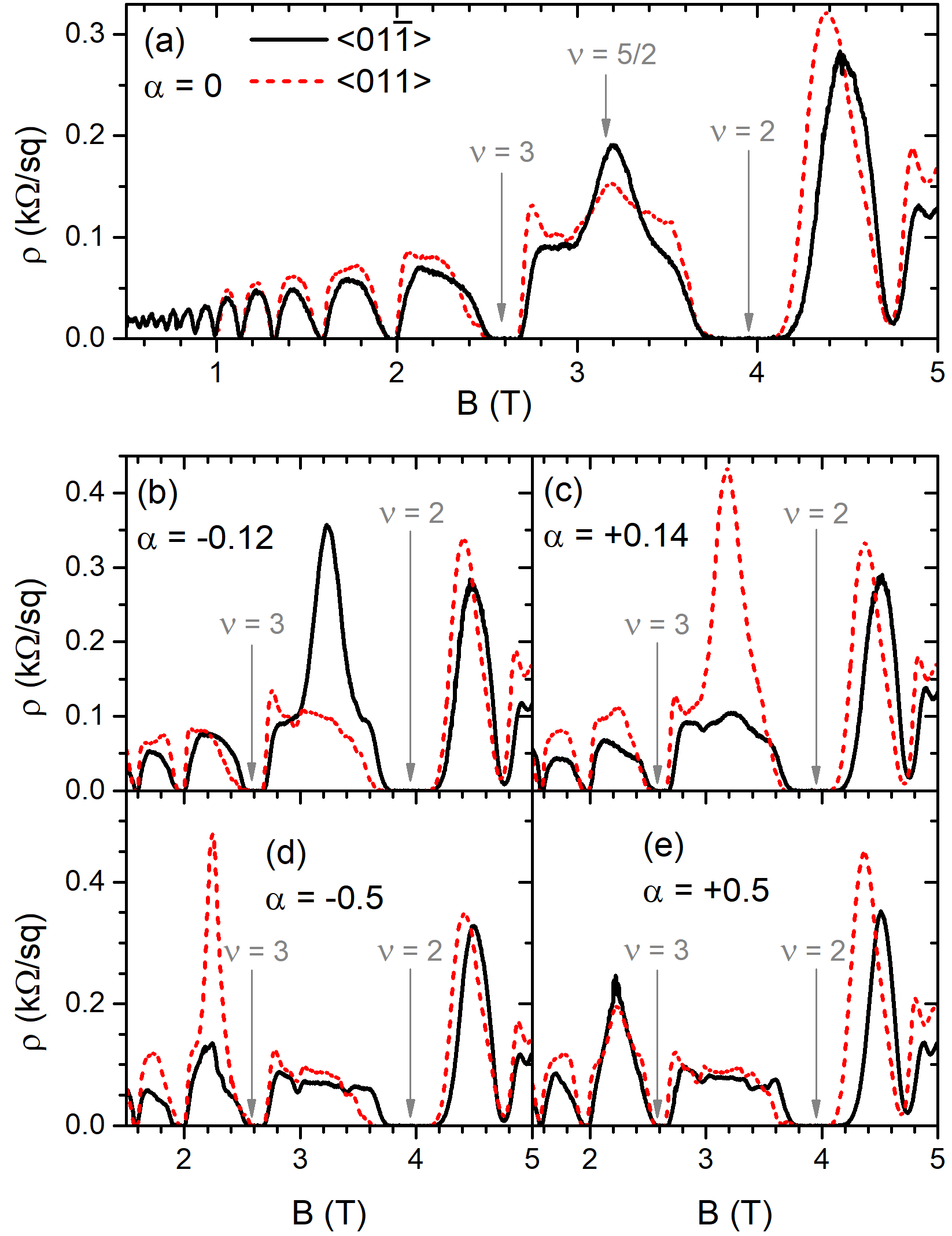
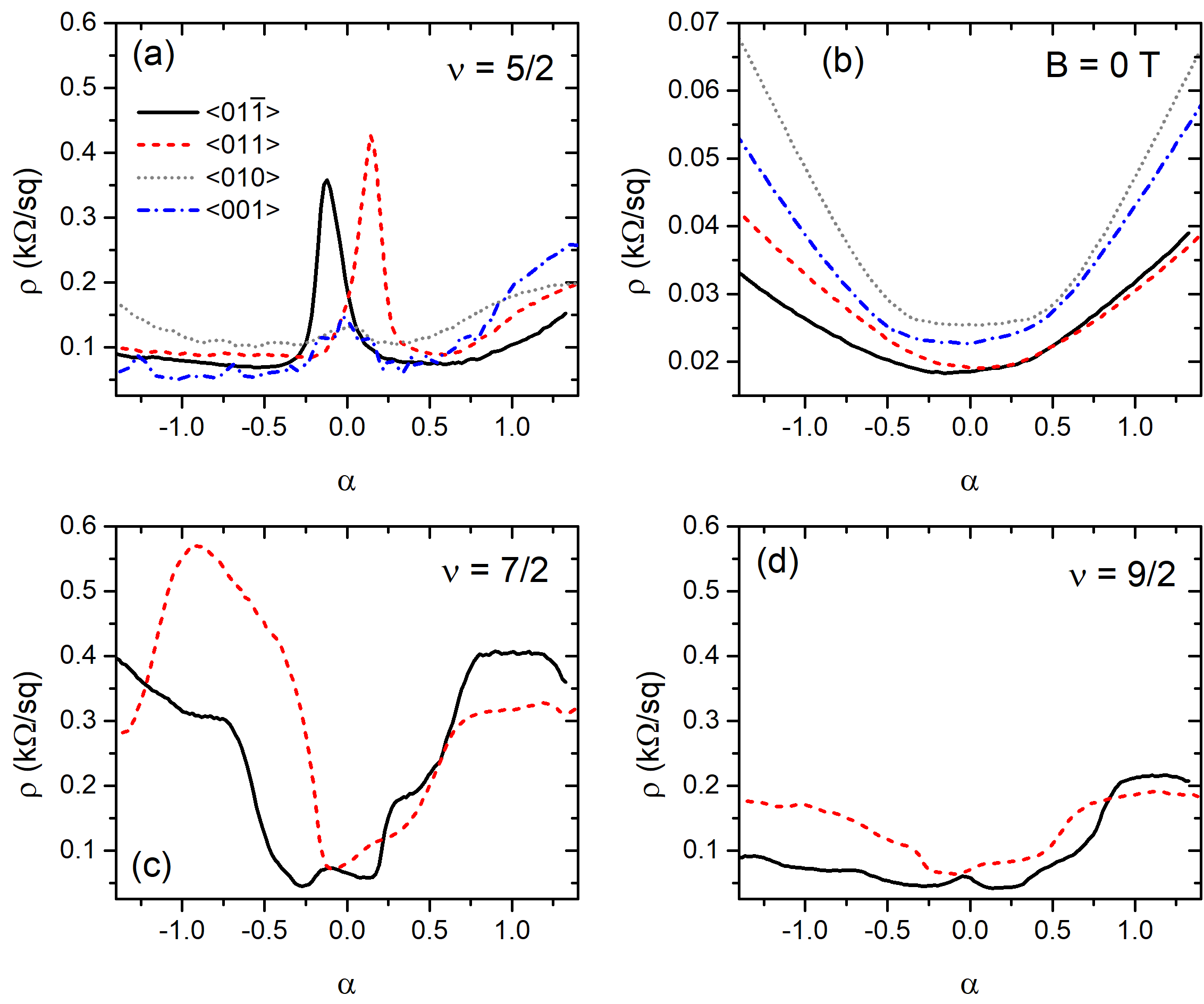
Figure 3(a) summarizes the dependence of the resistivity in all four directions on at , for the same density as Fig. 2. In contrast to the and directions, we do not see any significant peak in along the or directions, in agreement with previous results Manfra et al. (2006). For all four directions there is a general trend of increasing resistivity as increases beyond approximately 0.5, both at [Fig. 3(a)] and at T [Fig. 3(b)]. This may be related to increased scattering from GaAs/AlGaAs interface roughness disorder as the 2DHS wavefunction is pushed towards the edges of the QW at large [see Figs. 1(c) and 1(e)] Croxall et al. (2013). However, the sharp peaks in along the and directions, for small negative and positive respectively, have no counterpart at T.
We have looked for similar effects at [Fig. 3(c)] and [Fig. 3(d)]. At , for all values of we have studied, there is no evidence of anisotropy significantly greater than that at T. The behavior at is complex. Both and show a broad minimum at small , flanked by peaks at . It may be significant that the peaks in for occur at roughly the center of the broad minima in for . However, at , for , is significantly greater than [see also Fig. 2(d)], while, for positive , and are very similar in magnitude. While these observations are suggestive of stripe ordering at at certain , further investigations are required to determine the nature of this state.
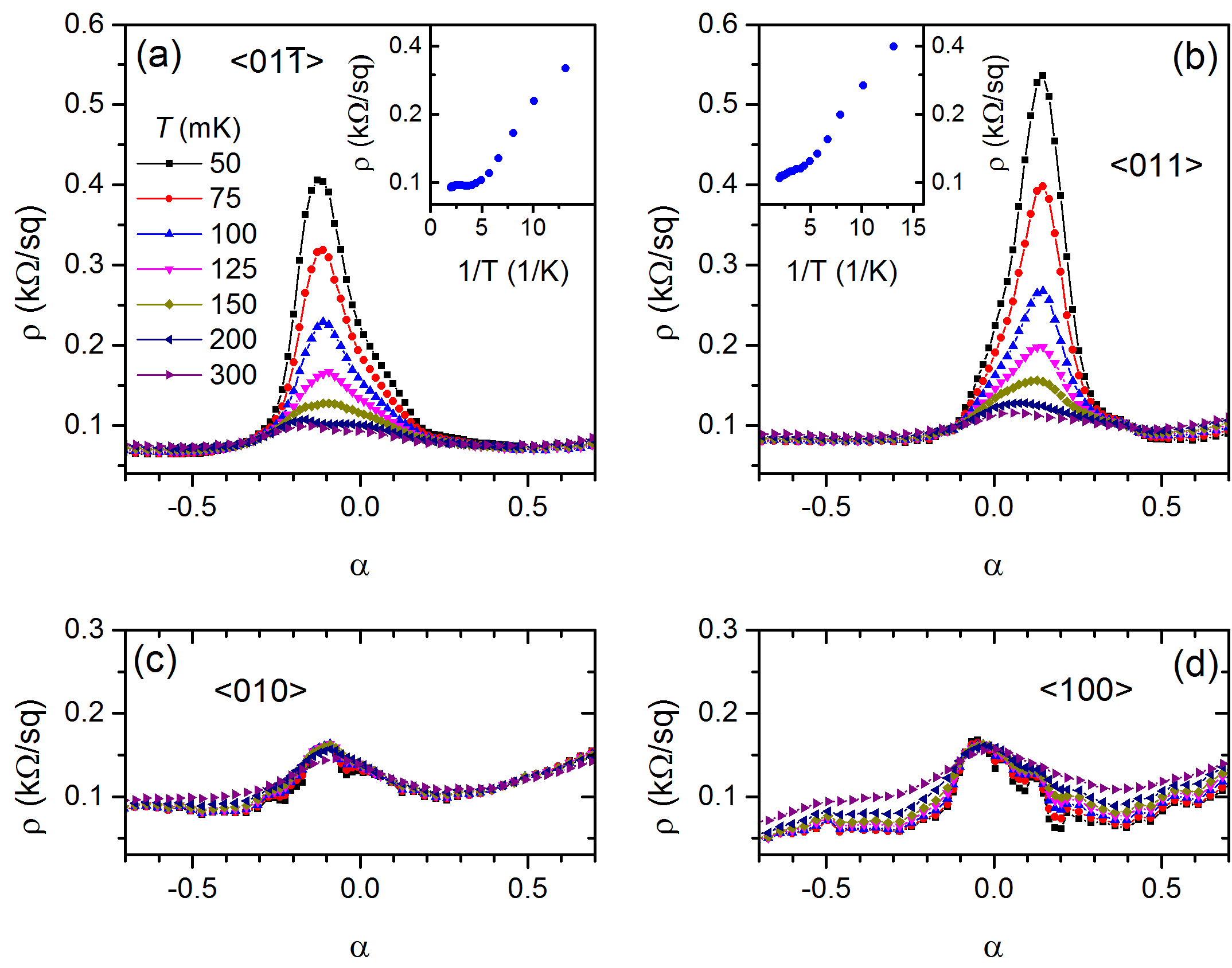
We now consider the temperature dependence of the resistivity in the anisotropic state at . In the and directions, is only weakly temperature dependent up to 300 mK [Figs. 4(c) and 4(d)]. The same is true in the and directions for , where the resistivity is isotropic [Figs. 4(a) and 4(b)]. However, the temperature dependence of the peak in () for small negative(positive) is insulating (). In common with other studies of quantum Hall nematic states Lilly et al. (1999a); Du et al. (1999); Wexler and Dorsey (2001); Cooper et al. (2002), the anisotropic state is destroyed by increasing temperature; in our case the resistance is isotropic for mK. Below this temperature, we find the peak resistivity follows [see insets to Figs. 4(a) and 4(b)], with characteristic temperature scale mK for both and at cm-2. We note that at the resistivity in all directions is only weakly temperature dependent, while at the broad peaks in and around have an insulating temperature dependence similar to that of the resistivity peaks at , suggestive of stripe behavior.
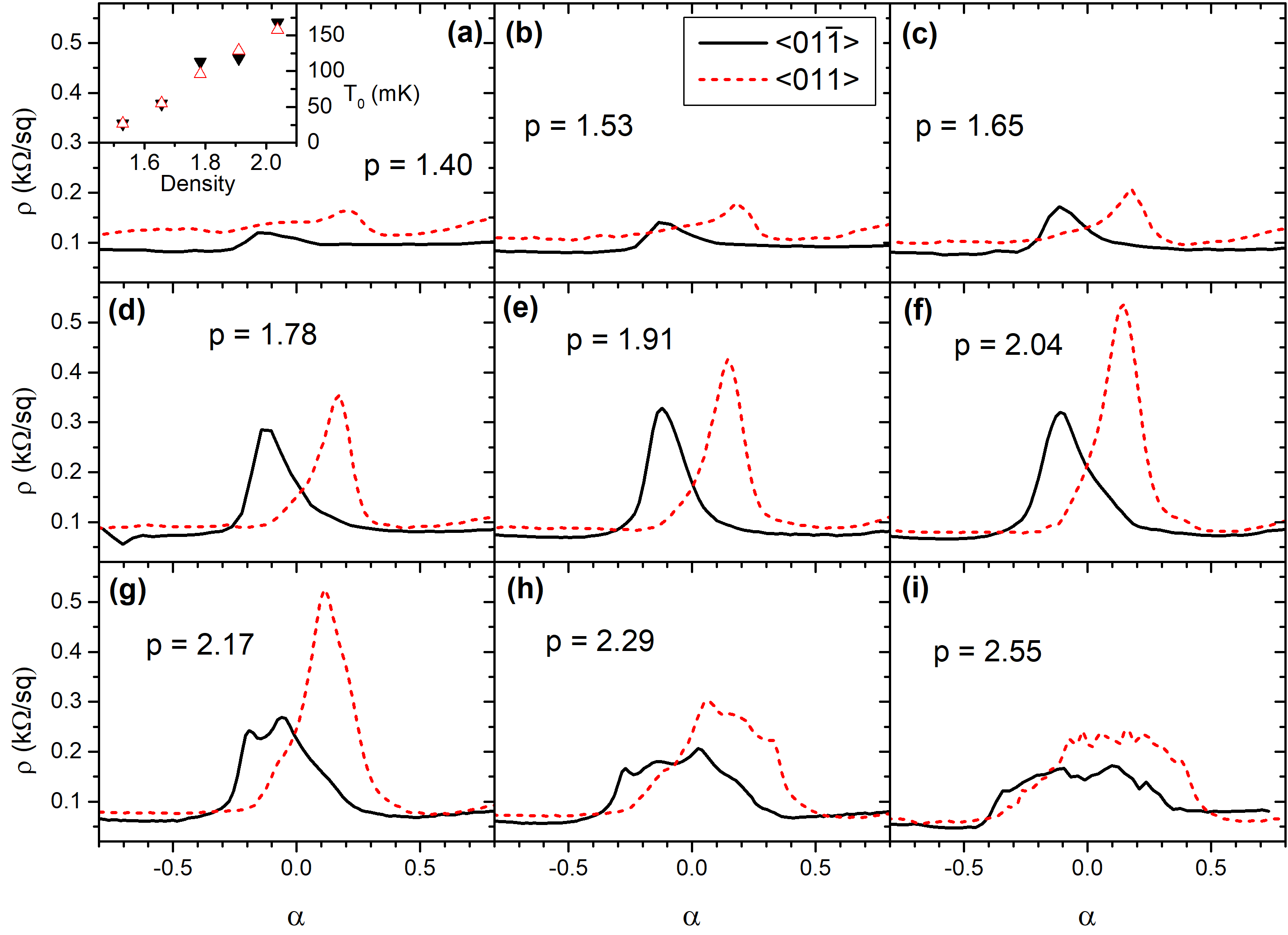
In Fig. 5 we explore the density dependence of the resistivity anisotropy at , comparing and at a range of densities. For all densities there is a peak in () centered at small negative(positive) . These peaks are strongest for cm-2. At lower density the peaks diminish, while at higher density the peaks become broader so that the degree of anisotropy is reduced. In all cases the temperature dependence of the peak resistance is insulating. For cm cm-2 we again find , with increasing linearly with density [see inset to Fig. 5(a)]. This may be related to the increase of the magnetic field, and hence the cyclotron energy, at as the density is increased Stanescu et al. (2000). At higher density the temperature dependence of the resistivity peaks is more similar to a power law, , with , so that we cannot identify a characteristic temperature scale.
It is not obvious whether the broad peaks in at high density arise from a nematic state, since the resistivity is approximately isotropic. However, given the continuous evolution of these peaks from the anisotropic state at cm-2, and their insulating temperature dependence, we suggest the nematic state may persist for cm-2. For 2DES quantum Hall nematics at , it is thought that the states with density modulations (“stripes”) along and are close in energy and that in certain circumstances domains of each orientation can co-exist Fil (2000); Cooper et al. (2004); Zhu et al. (2009). In our 2DHS at there may be domains of both orientations, with the dominant orientation controlled by both density and . While the nematic orientation seems to weaken at low density, and be stronger in one (-dependent) direction than another for cm-2, at higher density there could be a significant fraction of domains oriented in each direction.
Finally, we note that we could not find any signs of nematic ordering/anisotropic resistivity for 2DHSs in narrower QWs (10 nm and 15 nm), although this could be because of the lower mobility in narrower wells due to increased interface roughness scattering.
IV Discussion
Our results raise two questions: (1) Why does the nematic phase form in the 2DHS at only for small but non-zero and certain hole densities? (2) What is the symmetry breaking mechanism that orients the nematic and rotates it by when is reversed?
In 2DESs, nematic phases in a purely perpendicular magnetic field are usually only observed at half filling in the LLs, in agreement with theoretical studies Fogler and Koulakov (1997). In the LL at and the nematic state can be stabilised by an in-plane magnetic field Lilly et al. (1999b); Pan et al. (1999b); Jungwirth et al. (1999); Rezayi and Haldane (2000). Observations of nematic states without an in-plane field at and/or in 2DESs at very low density or under hydrostatic pressure Pan et al. (2014); Samkharadze et al. (2015); Schreiber et al. (2018) have been attributed to strong interaction-driven LL mixing when the ratio of the electron-electron interaction energy to the LL spacing is large. Here, is the magnetic length, is the permittivity, and is the cyclotron frequency. Stripe states have been observed at in tilted magnetic field in systems where the Zeeman energy is large compared to the cyclotron energy, so that the chemical potential lies in the LL Zhang et al. (2017); Hossain et al. (2018). Conversely, in wide QWs the nematic can be absent at because the chemical potential lies in, or close to, the LL of the second QW subband Pan et al. (2000); Xia et al. (2010).
Two-dimensional hole systems in GaAs/AlGaAs often show nematic phases at and/or Shayegan et al. (2000); Manfra et al. (2006, 2007); Takado et al. (2007); Koduvayur et al. (2011). The larger effective mass in the 2DHS reduces the cyclotron energy, significantly enhancing the LL mixing parameter . Holes in GaAs are also subject to significant spin-orbit coupling Winkler (2003). Manfra et al. observed an anisotropic state at and (but not at or ) in a 2DHS in a symmetrically-doped 20-nm-wide QW with cm-2, but not in samples with lower density or a strongly asymmetric confining potential Manfra et al. (2007). This was attributed to strong spin-orbit coupling that mixes the valence band states and alters the orbital structure of the hole LLs at Yang et al. (1985); Ekenberg and Altarelli (1985), thus modifying the effective hole-hole interaction potential MacDonald and Ekenberg (1989); Yang et al. (1990). By self-consistent calculations of the LL structure, Manfra et al. showed that their observations of a nematic phase correlated with the half-filled LL containing mostly orbitals, while isotropic states occurred for LLs containing significant amounts of the and orbitals. The LL mixing due to spin-orbit coupling depends strongly on the 2DHS density, the shape and width of the QW confining potential, and magnetic field Winkler (2003), so these factors will affect whether the anisotropic phase can form at various half-integer filling factors Manfra et al. (2007).
We suggest the nematic phase at in our 2DHS occurs because of Landau level mixing caused by both interactions and spin-orbit coupling. Both mixing mechanisms will be sensitive to the out-of-plane electric field, which may explain why the nematic is stable only at certain . The Rashba spin-orbit coupling term is proportional to . As illustrated in Figs. 1(c) to 1(e), increasing effectively decreases the QW width. While decreasing QW width may enhance the hole-hole interaction, it will also increase the QW subband spacing and hence suppress mixing of the valence bands. This could be the reason why the nematic disappears for large . However, these factors cannot account for what sets the orientation of the nematic ordering, especially the rotation of the stripes by when is reversed.
It is thought that the energy of the nematic state has local minima for orientation along or Fil (2000); Cooper et al. (2004); Zhu et al. (2009), but which of these has the lowest energy is found to depend on factors such as density Zhu et al. (2002); Cooper et al. (2004), 2DES depth Pollanen et al. (2015), strain Koduvayur et al. (2011), filling factor/spin Liu et al. (2013) and the orientation and magnitude of an in-plane magnetic field Pan et al. (1999b); Lilly et al. (1999b); Shi et al. (2016a, b, 2017). For unstrained samples on GaAs (100) surfaces, in a purely out-of-plane magnetic field, the and directions are expected to be equivalent. We now discuss several proposed symmetry-breaking mechanisms and whether they are likely to be relevant in our system.
Koduvayur et al. observed nematic states in a 2DHS at and subjected to an in-plane shear strain , where the high resistance direction was rotated by upon reversing the sign of (Ref. Koduvayur et al., 2011). These effects were explained by a strain-induced anisotropy of the exchange interaction, which preferentially orients the nematic density modulation along either or depending on the sign of . Koduvayur et al. argued that, since GaAs is a piezoelectric material, an out-of-plane electric field results in an in-plane strain, so the orientation of the nematic phases in unstrained devices could be related to asymmetries in the confining potential Koduvayur et al. (2011). The experiments of Ref. Pollanen et al., 2015 showed no effect of the confining potential asymmetry on the nematic orientation in GaAs 2DESs. However, the predicted strain-induced anisotropy of the Harteee-Fock energy is two orders of magnitude larger for holes than electrons Koduvayur et al. (2011). In our samples the anisotropy is maximized for average electric fields V/cm, resulting in (using , where cm/V, following Ref. Koduvayur et al., 2011). This is two orders of magnitude smaller than the strains applied by Koduvayur et al., so we do not think piezoelectric strain can account for our findings. Although we do not intentionally strain our samples, the fabrication technique of sample thinning before depositing the back gates could lead to residual strain. However, this strain would presumably be only weakly affected by the applied electric field, so it is difficult to see how it could lead to nematic phases in the or sections of our Hall bar with different orientations at different electric fields.
Sufficiently strong periodic potential modulations can affect the stripe orientation Mueed et al. (2016); Yoshioka (2001). It is possible that the interface roughness on opposite sides of our quantum well has corrugations that pin the stripes in one direction when the electric field pushes the wavefunction to one side of the well and in the orthogonal direction for the opposite electric field. However, we consider it unlikely that surface corrugations during MBE growth could rotate by during just 25 nm of GaAs growth, or be so different in areas of the sample less than 1 mm apart, and anisotropic interface roughness in MBE-grown 2DESs has been shown experimentally to have no consistent effect on the nematic orientation Willett et al. (2001a); Cooper et al. (2001).
Sodemann and MacDonald have argued that the combination of the Rashba and Dresselhaus spin-orbit interactions breaks rotational symmetry and could be responsible for orienting the nematic states of GaAs/AlGaAs 2D electron systems along the directions in most cases Sodemann and MacDonald (2008). Individually the Rashba and Dresselhaus effects would maintain rotational invariance, but this is broken by the two in combination. The predicted anisotropic contribution to the energy is
| (1) |
where is the angle between the stripes and the direction, is the stripe period, is the orbital LL degeneracy, is the coefficient of the Rashba(Dresselhaus) term in the spin-orbit Hamiltonian 333In a 2DES, the spin-orbit Hamiltonian can be written , where is mechanical momentum and is spin. and is a dimensionless number. The Rashba coefficient is strongly dependent on . Since is an odd function of , while is even, the stripes are expected to rotate by when the sign of the electric field is reversed. This theory was developed for 2D electron systems. Further theoretical work would be needed to determine whether a similar mechanism could operate in a 2DHS, where the functional forms of the Rashba and Dresselhaus terms are somewhat different and there is much stronger LL mixing. However, the symmetry of the Rashba and Dresselhaus terms with respect to should be the same for both electrons and holes Winkler (2000), so we suggest it could explain our results. For example, our observation of the nematic phase for only a narrow range of could be because anisotropy is maximised when the Rashba and Dresselhaus terms are of similar strength.
We note that Pollanen et al. made a detailed study of the effects of heterostructure asymmetry on the orientation of the 2DES nematic phase at (Ref. Pollanen et al., 2015). By varying the doping profile in quantum well structures, they found that the hard axis of the nematic state was always along the direction, independent of the sign of the average perpendicular electric field at the location of the 2DES Pollanen et al. (2015). This implied that the spin-orbit model of Ref. Sodemann and MacDonald, 2008 is not a dominant symmetry breaker in 2DESs. However, in GaAs the spin-orbit coupling is much stronger for holes than for electrons, so we do not think the findings of Pollanen et al. rule out a spin-orbit origin for our results.
Takhtamirov and Volkov Takhtamirov and Volkov (2000) and Rosenow and Scheidl Rosenow and Scheidl (2001) have shown that the asymmetric confinement potential in a GaAs/AlGaAs heterostructure leads to anisotropy in the electron effective mass even without spin-orbit coupling, which may explain the preferential stripe orientation along in GaAs 2DESs. This mechanism is also expected to be stronger for holes than for electrons Takhtamirov and Volkov (2000). However, we might expect the effective mass anisotropy, and presumably the stripe stability, to increase with increasing , while we find the anisotropy is destroyed beyond a critical .
We must point out that our calculation of contains significant uncertainty because the Fermi-level pinning on opposite sides and in different regions of the sample may differ slightly, and because the QW subband energies vary as a function of and . There is a small possibility that the peaks in resistance at could be occurring at . However, it is very unlikely that our error in calculating could be so different in different parts of the sample, or that the high resistance direction could be different in different parts of the sample if both parts of the sample really had . Different sample geometries (e.g. van der Pauw) could be useful in ruling out such effects because the resistance for the and directions could be measured in the same area of the sample.
V Conclusion
In conclusion, we have reported observations of a quantum Hall nematic state in a 2DHS in a GaAs QW at for a small, non-zero average perpendicular electric field , of typical magnitude V/m. The nematic orientation rotates by when the direction of reversed. This behavior may be related to the mixing of the hole Landau levels under the combined action of the Rashba and Dresselhaus spin-orbit coupling effects.
Acknowledgements
We thank I. Sodemann, A.H. MacDonald, A.R. Hamilton and N.R. Cooper for useful discussions. This work was supported by UK Engineering and Physical Sciences Research Council projects EP/H017720/1 and EP/J003417/1. A.F.C acknowledges funding from Trinity College at the University of Cambridge, UK. J.W acknowledges funding from the Herchel Smith Fund at the University of Cambridge. I.F. acknowledges funding from Toshiba Research Europe Limited.
The data presented in this article can be accessed at https://doi.org/10.17863/CAM.38773.
References
- Halperin et al. (1993) B. I. Halperin, P. A. Lee, and N. Read, Phys. Rev. B 47, 7312 (1993).
- Du et al. (1993) R. R. Du, H. L. Stormer, D. C. Tsui, L. N. Pfeiffer, and K. W. West, Phys. Rev. Lett. 70, 2944 (1993).
- Willett (1997) R. L. Willett, Adv. Phys. 46, 447 (1997).
- Willett et al. (1987) R. Willett, J. P. Eisenstein, H. L. Störmer, D. C. Tsui, A. C. Gossard, and J. H. English, Phys. Rev. Lett. 59, 1776 (1987).
- Pan et al. (1999a) W. Pan, J.-S. Xia, V. Shvarts, D. E. Adams, H. L. Stormer, D. C. Tsui, L. N. Pfeiffer, K. W. Baldwin, and K. W. West, Phys. Rev. Lett. 83, 3530 (1999a).
- Lilly et al. (1999a) M. P. Lilly, K. B. Cooper, J. P. Eisenstein, L. N. Pfeiffer, and K. W. West, Phys. Rev. Lett. 82, 394 (1999a).
- Du et al. (1999) R. Du, D. Tsui, H. Stormer, L. Pfeiffer, K. Baldwin, and K. West, Solid State Commun. 109, 389 (1999).
- Koulakov et al. (1996) A. A. Koulakov, M. M. Fogler, and B. I. Shklovskii, Phys. Rev. Lett. 76, 499 (1996).
- Fogler et al. (1996) M. M. Fogler, A. A. Koulakov, and B. I. Shklovskii, Phys. Rev. B 54, 1853 (1996).
- Moessner and Chalker (1996) R. Moessner and J. T. Chalker, Phys. Rev. B 54, 5006 (1996).
- Fradkin and Kivelson (1999) E. Fradkin and S. A. Kivelson, Phys. Rev. B 59, 8065 (1999).
- Fradkin et al. (2000) E. Fradkin, S. A. Kivelson, E. Manousakis, and K. Nho, Phys. Rev. Lett. 84, 1982 (2000).
- Wexler and Dorsey (2001) C. Wexler and A. T. Dorsey, Phys. Rev. B 64, 115312 (2001).
- Cooper et al. (2002) K. B. Cooper, M. P. Lilly, J. P. Eisenstein, L. N. Pfeiffer, and K. W. West, Phys. Rev. B 65, 241313 (2002).
- Fradkin et al. (2010) E. Fradkin, S. A. Kivelson, M. J. Lawler, J. P. Eisenstein, and A. P. Mackenzie, Annu. Rev. Condens. Matter Phys. 1, 153 (2010).
- Note (1) As well as the nematic, smectic and anisotropic crystal ground states are possible; see Q. Qian, J. Nakamura, S. Fallahi, G.C. Gardner, and M.J. Manfra, Nature Communications 8, 1536 (2017) and references therein.
- Zhu et al. (2002) J. Zhu, W. Pan, H. L. Stormer, L. N. Pfeiffer, and K. W. West, Phys. Rev. Lett. 88, 116803 (2002).
- Cooper et al. (2004) K. B. Cooper, J. P. Eisenstein, L. N. Pfeiffer, and K. W. West, Phys. Rev. Lett. 92, 026806 (2004).
- Liu et al. (2013) Y. Liu, D. Kamburov, M. Shayegan, L. N. Pfeiffer, K. W. West, and K. W. Baldwin, Phys. Rev. B 87, 075314 (2013).
- Pollanen et al. (2015) J. Pollanen, K. B. Cooper, S. Brandsen, J. P. Eisenstein, L. N. Pfeiffer, and K. W. West, Phys. Rev. B 92, 115410 (2015).
- MacDonald and Fisher (2000) A. H. MacDonald and M. P. A. Fisher, Phys. Rev. B 61, 5724 (2000).
- Cooper et al. (2001) K. Cooper, M. Lilly, J. Eisenstein, T. Jungwirth, L. Pfeiffer, and K. West, Solid State Commun. 119, 89 (2001).
- Willett et al. (2001a) R. L. Willett, J. W. P. Hsu, D. Natelson, K. W. West, and L. N. Pfeiffer, Phys. Rev. Lett. 87, 126803 (2001a).
- Shi et al. (2016a) Q. Shi, M. A. Zudov, J. D. Watson, G. C. Gardner, and M. J. Manfra, Phys. Rev. B 93, 121404 (2016a).
- Shi et al. (2016b) Q. Shi, M. A. Zudov, J. D. Watson, G. C. Gardner, and M. J. Manfra, Phys. Rev. B 93, 121411 (2016b).
- Shi et al. (2017) Q. Shi, M. A. Zudov, Q. Qian, J. D. Watson, and M. J. Manfra, Phys. Rev. B 95, 161303 (2017).
- Lilly et al. (1999b) M. P. Lilly, K. B. Cooper, J. P. Eisenstein, L. N. Pfeiffer, and K. W. West, Phys. Rev. Lett. 83, 824 (1999b).
- Pan et al. (1999b) W. Pan, R. R. Du, H. L. Stormer, D. C. Tsui, L. N. Pfeiffer, K. W. Baldwin, and K. W. West, Phys. Rev. Lett. 83, 820 (1999b).
- Xia et al. (2010) J. Xia, V. Cvicek, J. P. Eisenstein, L. N. Pfeiffer, and K. W. West, Phys. Rev. Lett. 105, 176807 (2010).
- Jungwirth et al. (1999) T. Jungwirth, A. H. MacDonald, L. Smrc̆ka, and S. M. Girvin, Phys. Rev. B 60, 15574 (1999).
- Stanescu et al. (2000) T. D. Stanescu, I. Martin, and P. Phillips, Phys. Rev. Lett. 84, 1288 (2000).
- Mueed et al. (2016) M. A. Mueed, Md. Shafayat Hossain, L. N. Pfeiffer, K. W. West, K. W. Baldwin, and M. Shayegan, Phys. Rev. Lett. 117, 076803 (2016).
- Rezayi and Haldane (2000) E. H. Rezayi and F. D. M. Haldane, Phys. Rev. Lett. 84, 4685 (2000).
- Samkharadze et al. (2015) N. Samkharadze, K. A. Schreiber, G. C. Gardner, M. J. Manfra, E. Fradkin, and G. A. Csáthy, Nat. Phys. 12, 191 (2015).
- Schreiber et al. (2018) K. A. Schreiber, N. Samkharadze, G. C. Gardner, Y. Lyanda-Geller, M. J. Manfra, L. N. Pfeiffer, K. W. West, and G. A. Csáthy, Nat. Commun. 9, 2400 (2018).
- Shayegan et al. (2000) M. Shayegan, H. Manoharan, S. Papadakis, and E. Poortere, Physica E: Low-dimensional Systems and Nanostructures 6, 40 (2000).
- Manfra et al. (2006) M. J. Manfra, Z. Jiang, S. H. Simon, L. N. Pfeiffer, K. W. West, and A. M. Sergent, e-print arXiv:cond-mat/0603173v1 (2006).
- Manfra et al. (2007) M. J. Manfra, R. de Picciotto, Z. Jiang, S. H. Simon, L. N. Pfeiffer, K. W. West, and A. M. Sergent, Phys. Rev. Lett. 98, 206804 (2007).
- Takado et al. (2007) H. Takado, Y. Hashimoto, A. Endo, S. Katsumoto, and Y. Iye, J. Phys. Soc. Jpn. 76, 074712 (2007).
- Koduvayur et al. (2011) S. P. Koduvayur, Y. Lyanda-Geller, S. Khlebnikov, G. Csathy, M. J. Manfra, L. N. Pfeiffer, K. W. West, and L. P. Rokhinson, Phys. Rev. Lett. 106, 016804 (2011).
- Croxall et al. (2013) A. F. Croxall, B. Zheng, F. Sfigakis, K. Das Gupta, I. Farrer, C. A. Nicoll, H. E. Beere, and D. A. Ritchie, Appl. Phys. Lett. 102, 082105 (2013).
- Marcellina et al. (2018) E. Marcellina, A. Srinivasan, D. S. Miserev, A. F. Croxall, D. A. Ritchie, I. Farrer, O. P. Sushkov, D. Culcer, and A. R. Hamilton, Phys. Rev. Lett. 121, 077701 (2018).
- Sodemann and MacDonald (2008) I. Sodemann and A. MacDonald, e-print arXiv:1307.5489v1 (2008).
- Note (2) Figures 1(c) to (e) are calculated using the nextnano++ software, see https://www.nextnano.de/.
- Simon (1999) S. H. Simon, Phys. Rev. Lett. 83, 4223 (1999).
- Willett et al. (2001b) R. L. Willett, K. W. West, and L. N. Pfeiffer, Phys. Rev. Lett. 87, 196805 (2001b).
- Fil (2000) D. V. Fil, Low Temp. Phys. 26, 581 (2000).
- Zhu et al. (2009) H. Zhu, G. Sambandamurthy, L. W. Engel, D. C. Tsui, L. N. Pfeiffer, and K. W. West, Phys. Rev. Lett. 102, 136804 (2009).
- Fogler and Koulakov (1997) M. M. Fogler and A. A. Koulakov, Phys. Rev. B 55, 9326 (1997).
- Pan et al. (2014) W. Pan, A. Serafin, J. S. Xia, L. Yin, N. S. Sullivan, K. W. Baldwin, K. W. West, L. N. Pfeiffer, and D. C. Tsui, Phys. Rev. B 89, 241302 (2014).
- Zhang et al. (2017) P. Zhang, R. Liu, R.-R. Du, L. N. Pfeiffer, and K. W. West, Phys. Rev. B 95, 155316 (2017).
- Hossain et al. (2018) Md. Shafayat Hossain, M. A. Mueed, M. K. Ma, Y. J. Chung, L. N. Pfeiffer, K. W. West, K. W. Baldwin, and M. Shayegan, Phys. Rev. B 98, 081109 (2018).
- Pan et al. (2000) W. Pan, T. Jungwirth, H. L. Stormer, D. C. Tsui, A. H. MacDonald, S. M. Girvin, L. Smrc̆ka, L. N. Pfeiffer, K. W. Baldwin, and K. W. West, Phys. Rev. Lett. 85, 3257 (2000).
- Winkler (2003) R. Winkler, Spin-Orbit Coupling Effects in Two-Dimensional Electron and Hole Systems (Springer-Verlag, New York, 2003).
- Yang et al. (1985) S.-R. Eric Yang, D. A. Broido, and L. J. Sham, Phys. Rev. B 32, 6630 (1985).
- Ekenberg and Altarelli (1985) U. Ekenberg and M. Altarelli, Phys. Rev. B 32, 3712 (1985).
- MacDonald and Ekenberg (1989) A. H. MacDonald and U. Ekenberg, Phys. Rev. B 39, 5959 (1989).
- Yang et al. (1990) S.-R. Eric Yang, A. H. MacDonald, and D. Yoshioka, Phys. Rev. B 41, 1290 (1990).
- Yoshioka (2001) D. Yoshioka, J. Phys. Soc. Jpn. 70, 2836 (2001).
- Note (3) In a 2DES, the spin-orbit Hamiltonian can be written , where is mechanical momentum and is spin.
- Winkler (2000) R. Winkler, Phys. Rev. B 62, 4245 (2000).
- Takhtamirov and Volkov (2000) É. E. Takhtamirov and V. A. Volkov, JETP Lett. 71, 422 (2000).
- Rosenow and Scheidl (2001) B. Rosenow and S. Scheidl, Int. J. Mod. Phys. B 15, 1905 (2001).