Dimension Engineering of Single-Layer PtN2 with the Cairo Tessellation
Abstract
Single-layer PtN2 exhibits an intriguing structure consisting of a tessellation pattern called the Cairo tessellation of type 2 pentagons, which belong to one of the existing 15 types of convex pentagons discovered so far that can monohedrally tile a plane. Single-layer PtN2 has also been predicted to show semiconducting behavior with direct band gaps. Full exploration of the structure-property relationship awaits the successful exfoliation or synthesis of this novel single-layer material, which depends on the structure of its bulk counterpart with the same stoichiometry to some extent. Bulk PtN2 with the pyrite structure is commonly regarded as the most stable structure in the literature. But comparing the energies of single-layer PtN2 and bulk PtN2 leads to a dilemma that a single-layer material is more stable than its bulk counterpart. To solve this dilemma, we propose stacking single-layer PtN2 sheets infinitely to form a new bulk structure of PtN2. The resulting tetrahedral layered structure is energetically more stable than the pyrite structure and single-layer PtN2. We also find that the predicted bulk structure is metallic, in contrast to the semiconducting pyrite structure. In addition to predicting the 3D structure, we explore the possibility of rolling single-layer PtN2 sheets into nanotubes. The required energies are comparable to those needed to form carbon or boron nitride nanotubes from their single-layer sheets, implying the feasibility of obtaining PtN2 nanotubes. We finally study the electronic structures of PtN2 nanotubes and find that the band gaps of PtN2 nanotubes are tunable by changing the number of unit cells of single-layer PtN2 used to construct the nanotubes. Our work shows that dimension engineering of PtN2 not only leads to a more stable 3D structure but also 1D materials with novel properties.
I Introduction
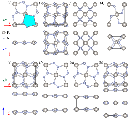
A number of two-dimensional (2D) materials have been predicted and recorded in various databases such as the computational 2D materials database (C2DB)Haastrup et al. (2018) and Materialsweb.Ashton et al. (2017) But many of these materials, in spite of their exotic properties, exhibit no known bulk counterparts especially those with the same stoichiometry, making it challenging to obtain these 2D materials. Being such an example, single-layer platinum nitride PtN2 has recently been predicted in several theoretical studies.Liu et al. (2018); Zhao et al. (2019); Yuan et al. (2019) The reason for the uniqueness of this single-layer material is twofold: First, the structure as illustrated in Fig.1(a) is completely planar with a tessellation of type 2 pentagons that are able to tessellate a plane; This tessellation is called the Cairo tessellation, as it appears in the streets of Cairo.Wells (1991) Second, it is a semiconductor with predicted high carrier mobility and Young’s modulus.Liu et al. (2018) The peculiar structure and properties of single-layer PtN2 call for its synthesis, which largely rely on the existence of stable structure of bulk PtN2.
Even without in the above context of single-layer PtN2, bulk PtN2 on its own has attracted considerable attention as an example in the family of transition-metal nitrides, which generally possess notable electrical, mechanical, and thermal properties.Yamanaka (1998); Young et al. (2006); Fu et al. (2009) The pyrite structure of bulk PtN2 is commonly regarded as the most stable.Yu et al. (2006); Gou et al. (2006); Crowhurst et al. (2006); Young et al. (2006) Figure 1(b) illustrates the pyrite structure, consisting of Pt atoms occupying the lattice sites of a face-centered cubic (fcc) lattice and each Pt atom is six-fold coordinated with N atoms to form corner-sharing Pt-N octahedra. Two other possible structures including the fluorite (as shown in Fig.1(c)) and marcasite (as shown in Fig.1(d)) structures have also been studied.Yu and Zhang (2005); Yu et al. (2006); Chen et al. (2007) In the fluorite structure, Pt atoms are also located at the fcc lattice sites, but each Pt atom has eight nearest neighboring N atoms. In the marcasite structure, the Pt and N atoms also form corner-sharing Pt-N octahedra, but the Pt atoms occupy the sites of a body-centered tetragonal lattice.
In addition to 2D materials, 1D nanotubes have sparked wide interest since the discovery of carbon nanotubes (CNTs).Iijima (1991); Bacsa et al. (1995) Their mechanical, electrical, and optical properties can be tuned by modifying the diameters and charality,Hamada et al. (1992) making CNTs promising for a wealth of applications,Koziol et al. (2007) such as field emission electron source De Heer et al. (1995) and light-emitting diodes.Chen et al. (2005a) Successful fabrication of CNTs indicates the feasibility of obtaining non-carbon nanotubes based on other single-layer materials. Indeed, extensive experimental and theoretical research has been extended to study boron nitride BN, carbonitrides BxCyNz, and transition-metal dichalcogenides ( and represent transition-metal and chalcogen elements, respectively) nanotubes.Zettl (1996); Pokropivny (2001); Ivanovskii (2002)
Although many 2D materials and their structures have been predicted based on the bulk counterparts of these 2D materials with the same stoichiometry, we revert this process in this work by first showing a counter-intuitive result that single-layer PtN2 is more energetically stable than bulk PtN2 with the pyrite structure. We then study the interactions between two layers of PtN2 and suggest a layered structure with on-top stacking of single-layer PtN2 sheets as the more stable bulk structure. Furthermore, due to the above-mentioned excellent properties of nanotubes, we explore the structure-property relationships of PtN2 nanotubes.
II Methods
All the DFT calculations are performed using the Vienna Ab-initio Simulation Package (VASP, version 5.4.4)Kresse and Furthmüller (1996) We apply the Perdew-Burke-Ernzerhof (PBE) functional to approximate the exchange-correlation interactions.Perdew et al. (1996) We use Grimme’s DFT-D3 method to describe the van der Waals (vdW) interactions in bilayer PtN2 and our proposed layered structure of bulk PtN2.Grimme et al. (2010) We also use the optB88-vdW functional to compare against the accuracy of some of the DFT-D3 results.Dion et al. (2004); Román-Pérez and Soler (2009); Klimeš et al. (2011) We use the standard potential datasets created with the PBE functional for Pt and N generated according to the projector augmented wave method .Blöchl (1994); Kresse and Joubert (1999) These datasets treat the 5 and 6 electrons of Pt atoms and the 2 and 2 electrons of N atoms as valence electrons. Plane waves with their cut-off kinetic energies below 550 eV are used to approximate the electron wave functions. We use a -centered Monkhorst-PackMonkhorst and Pack (1976) -point grid for single-layer and bilayer PtN2, and a grid for bulk PtN2 with the pyrite, fluorite, marcasite, and AB-stacked structures, and a grid for bulk PtN2 with the tetragonal AA-stacked layered structure, and a grid for PtN2, carbon, and boron nitride nanotubes, to sample the points in the reciprocal space. A sufficiently large vacuum spacing ( 18.0 Å) is applied to the slabs of single-layer and bilayer PtN2 and nanotubes to avoid the image interactions due to the periodic boundary conditions. The lattice constants and atomic coordinates of bulk PtN2 with different structures are completely optimized. For single-layer and bilayer PtN2, we optimize the in-plane lattice constant and the atomic positions. For the PtN2 nanotubes, we relax only the lattice constant along the tube direction and the atomic positions. The force threshold value for all of these geometry optimizations is the same, i.e., 0.01 eV/Å.
III Results and Discussion
We first benchmark our calculations on single-layer PtN2 with previous theoretical studies. Our calculated in-plane lattice constant (4.81Å) is consistent with the reported results (4.80,Liu et al. (2018) 4.81,Yuan et al. (2019) and 4.83Zhao et al. (2019) Å). For the electronic structure, Fig. 2(a) shows the density of states (DOS) of single-layer PtN2 calculated with the PBE and HSE06 functionals. The PBE functional seriously underestimates the band gap of single-layer PtN2. The PBE DOS curve shows that this functional actually leads to a conclusion that single-layer PtN2 is metallic, agreeing with the rather small bandgaps (0.075 and 0.07 eV) reported in Refs. [Zhao et al., 2019] and [Yuan et al., 2019], respectively. Our HSE06 DOS shows a corrected band gap of single-layer PtN2 as 1.11 eV, which is the same as the band gaps reported in Refs.[Liu et al., 2018] and [Yuan et al., 2019]. Note that the work of Yang et al also considers spin-orbit coupling (SOC) and the PBE+SOC and HSE06+SOC band gaps (0.33 and 1.17 eV) are slightly larger than the PBE and HSE06 band gaps.Liu et al. (2018)
We next calculate the energy difference between single-layer PtN2 and bulk PtN2 with the pyrite, fluorite, and marcasite structures. This energy difference (i.e., -, the formation energy of 2D materials) is a metric of the energy cost to exfoliate a single-layer nanosheet from its 3D counterpart and also an indicator of the feasibility of chemical synthesis.Singh et al. (2015) We find the formation energies with reference to the three bulk structures are all negative: -168, -1076, and -207 meV/atom. The more negative formation energy implies the less stable of the bulk structure used for comparison. These energy differences therefore show that the pyrite structure is the most stable in comparison with the fluoride and marcasite structures, consistent with previous theoretical studies.Chen et al. (2010); Crowhurst et al. (2006); Yu et al. (2006) We conclude that single-layer PtN2 is more stable than the pyrite structure. More important, the negative formation energies show that all the three bulk structures used for references are not the ground state of bulk PtN2. In parallel with this observation, we also perform the same calculations on single-layer graphene and compare its energy to the face-centered-cubic diamond structure. We obtain a negative formation energy of -128 meV/atom using the PBE functional, which is expected as the bulk ground state is graphite.
| Method | Single-layer | Bulk-pyrite | Bulk-fluorite | Bulk-marcasite | Bilayer-AB | Bilayer-AA | Bulk-AB |
|---|---|---|---|---|---|---|---|
| PBE | 34 | 202 | 1110 | 241 | 33 | 25 | 97 |
| DFT-D3 | 199 | 139 | 1067 | 184 | 156 | 130 | 156 |
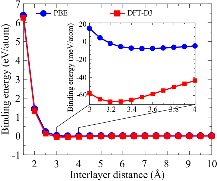
To search for the more stable bulk structure, we begin with studying the energy change by stacking two sheets of single-layer PtN2 to form bilayer PtN2. We account for two types of stacking for bilayer PtN2. One is called the AB stacking (see Fig. 1(e)), where the Pt atoms in one layer of bilayer PtN2 are located above/below the center of a pair of N atoms in another layer. The other one is the AA stacking (see Fig. 1(f)), where the second layer is located on top of the first layer. We find that AB-stacked bilayer PtN2 is energetically less stable than the AA-stacked structure by 8 meV/atom, so we focus on the AA-stacked bilayer PtN2 and compute the binding energy between the two layers defined as = -2. Figure 3 displays the of AA-stacked bilayer PtN2 as a function of the interlayer distance. As can be seen, without using the DFT-D3 method to describe the vdW interactions, the values resulting from the interactions between the two PtN2 layers are negligibly small with the maximum binding energy of -9 meV/atom. Taking into account the vdW interactions, the binding energy is corrected to -69 meV/atom (we obtain the same binding energy using the optB88-vdW functional), which is similar to the binding energy (-31.1 meV/atom) of AA-stacked bilayer graphene calculated using the DFT-D method,Mostaani et al. (2015) showing the weak interactions between single-layer PtN2 sheets.
Because bilayer AA-stacked PtN2 is more stable than single-layer PtN2, we expect to stack an infinite number of single-layer PtN2 sheets in the AA-stacking manner to result in a more stable structure of bulk PtN2 as illustrated in Fig. 1(g). A symmetry analysis of this infinitely AA-stacked layered structure shows that the bulk structure is tetragonal with the space group P4/mbm (No.127). We henceforth refer to this new bulk structure as the tetragonal layered (TL) structure. For the completeness of comparison, we also compute the energy of the bulk structure with AB-stacked layers (see Fig. 1(h)). We find that the TL structure is the most stable among the eight structures displayed in Fig. 1. Table 1 lists all the relative energies of the eight structures using the energy of the TL structure as the reference. The lattice constants of these two bulk structures are reported in Table 2. With the new bulk structure, the formation energies of single-layer PtN2 become physically positive, which are 34 and 199 meV/atom calculated with the PBE and DFT-D3 methods, respectively. These small formation energies manifest the weak interactions between layers and also indicate a feasible approach to obtain single-layer may be the mechanical exfoliation method as used to obtain single-layer graphene.Novoselov et al. (2004)
Since we have identified the more energetically stable structure of bulk PtN2, we now examine the mechanical stability of bulk PtN2 with the TL structure. We also calculate the same properties of bulk PtN2 with the pyrite structure for comparison, as the pyrite structure is the most stable among the previously reported bulk structures. Table 2 summarizes the predicted independent elastic stiffness constants for cubic and tetragonal PtN2 using a symmetry-general approach.Le Page and Saxe (2002). According to Born’s criteria of mechanical stability, the following conditions:Mouhat and Coudert (2014)
| (1) |
and
| (2) |
need to be satisfied for cubic and tetragonal PtN2, respectively. The computed elastic constants show that both the pyrite and TL structures of bulk PtN2 are mechanically stable.
| Structure | Method | ||||||||||||
|---|---|---|---|---|---|---|---|---|---|---|---|---|---|
| Pyrite | PBE | 4.85 | 4.85 | 4.85 | 695 | 87 | - | - | 133 | - | 290 | 187 | 22.5 |
| DFT-D3 | 4.82 | 4.82 | 4.82 | 746 | 93 | - | - | 136 | - | 311 | 195 | 22.3 | |
| LDA-NC111Ref.[García et al., 2018]; NC: norm-conserving pseudopotentials | 4.81 | 4.81 | 4.81 | 828 | 113 | - | - | 155 | - | 351 | 218 | 23.7, 27.7222Elastic stiffness constants are calculated from only the Voigt approximation. | |
| PW91-PAW333Ref.[Liu et al., 2014] | 4.88 | 4.88 | 4.88 | 662 | 69 | - | - | 129 | - | 267 | 181 | 23.7 | |
| LDA-LAPW444Ref.[Yu et al., 2006]; LAPW: linearized augmented plane waves | 4.77 | 4.77 | 4.77 | 824 | 117 | - | - | 152 | - | 353 | 215 | 22.9 | |
| PBE-LAPWd | 4.86 | 4.86 | 4.86 | 668 | 78 | - | - | 133 | - | 275 | 184 | 23.5 | |
| TL | PBE | 4.83 | 4.83 | 3.07 | 709 | 120 | 18 | 55 | 14 | 135 | 125 | 74 | 10.5 |
| DFT-D3 | 4.81 | 4.81 | 2.90 | 782 | 134 | 17 | 110 | 18 | 143 | 159 | 87 | 10.4 |
Hardness is an important property of platinum nitrides for their engineering applications.Chen et al. (2005b) We therefore calculate the Vicker hardness of bulk PtN2 with the pyrite and TL structures using the following empirical equation:Chen et al. (2011)
| (3) |
where the bulk and shear moduli ( and ) are calculated using the Voigt?-Reuss-?Hill (VRH) approximation:Voigt (1928); Hill (1952)
| (4) |
and
| (5) |
and are the upper bounds of bulk and shear moduli written as
| (6) |
and
| (7) |
respectively. and are the lower bounds of bulk and shear moduli, i.e.,
| (8) |
and
| (9) |
where are the elastic compliant constants and matrix is equal to the inverse of matrix . Table 2 lists the predicted and , and obtained from using the PBE and DFE-D3 methods. Our calculated elastic constants agree well with those reported Refs. [Liu et al., 2014] and [Yu et al., 2006] computed using the PW91 and PBE functionals with the general gradient approximation.Perdew et al. (1992) The local-density approximations (LDA)Kohn and Sham (1965); Ceperley and Alder (1980) are also used in Refs. [García et al., 2018] and [Yu et al., 2006], but this method seems to lead to larger elastic constants. However, the resulting hardness (22.5 GPa) in this work is similar to those in all the references, in spite of the methods used. Although several elastic stiffness constants of the TL structure (e.g., are significantly affected by the consideration of the vdW interactions, Table 2 also shows that our hardness values from the PBE and DFT-D3 methods are similar. The much smaller Vicker hardness of the TL structure suggests that it is much softer than the pyrite structure. This softness appears to be a common feature for layered materials such as graphite in contrast to superhard diamond.Hornyak et al. (2008)
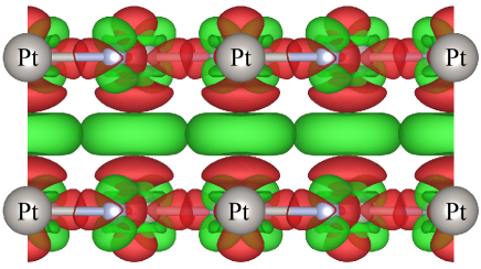
We now compare the electronic structures of bulk PtN2 with the pyrite and TL structures. Figure 2(b) shows the density of states of bulk PtN2 with the pyrite and TL structures calculated with the PBE and HSE06 functionals. For the former structure, both the PBE and HSE06 functionals predict that it is semiconducting and the band gaps are 1.35 and 2.22 eV, respectively. Our calculated PBE band gap is consistent with the previously reported band gap of 1.30 eV.Young et al. (2006) For the TL structure, the PBE and HSE06 functionals consistently show that the structure is metallic. To gain a qualitative understanding of the semiconductor-to-metal transition as the number of single-layer sheets increases, we calculate the charge density difference between AA-stacked bilayer PtN2 and two isolated single-layer PtN2 sheets. Figure 4 shows that the electrons of Pt atoms in both layers are transferred to the region between two Pt atoms, when the two layers interact to form bilayer PtN2. These electrons between the layers form Pt-Pt metallic bonds, leading to the metallic behavior of bilayer as well as bulk PtN2. In other words, the interlayer interactions in bilayer PtN2 or bulk PtN2 with the TL structure consist of mixed vdW and metallic bonding types. Note that the bond strength of these metallic bonds is small as reflected by the small isosurface value. We also expect the metallic bonding is significantly smaller than the vdW interactions, as including the vdW interactions drastically changes the energy difference between single-layer and bilayer PtN2 (see Table 1). Extracting a sheet of single-layer PtN2 from bilayer and bulk PtN2 prohibits the delocalization of the electrons. As a result, the electrons are localized around Pt atoms in the region enclosed by the red isosurface as shown in Fig.4, causing single-layer PtN2 to be semiconducting.
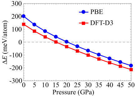
Experiments on bulk PtN2 with the pyrite structure indicate the importance of stabilizing this bulk phase by external pressure.Gregoryanz et al. (2004); Ivanovskii (2009) We therefore compare the stability of bulk PtN2 with the pyrite and TL structures at different pressures by computing their energy difference = -. Figure 5 shows as a function of pressure calculated with the PBE and DFT-D3 methods. The two curves reveal the same trend: changes almost linearly from positive to negative as pressure increases, showing that the TL structure is more stable below a critical pressure, above which the pyrite structure is more stable. This trend may be caused by the exponentially increased energy as the interlayer distance in the TL structure decreases due to the pressure (see Fig.3). We also find that the critical pressures resulted from the PBE and DFT-D3 methods are similar. For the PBE method, the transition pressure is around 20 GPa; For the latter method, the pressure is about 15 GPa.
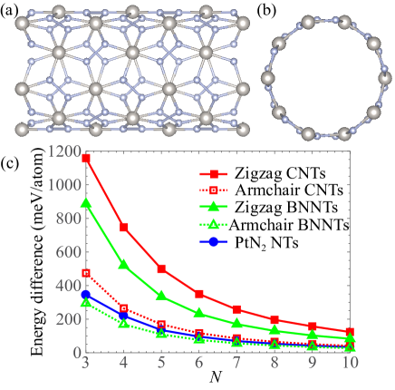
Having studied the case of increasing the dimension of PtN2 from 2D to 3D, we set to reduce the dimension to 1D to obtain PtN2 nanotubes. Many 2D materials such as single-layer graphene and boron nitride have their corresponding forms of nanotubes and exhibit novel properties.Zhi et al. (2010); Chen et al. (2017) We create simulation models of PtN2 nanotubes by wrapping 1 1 (3 10) supercells of single-layer PtN2 about the axis as shown in Fig.1(a). Due to the square symmetry of single-layer PtN2, wrapping the supercells about the axis leads to the same nanotubes. The integer therefore controls the diameters of the nanotubes. Figure 6(a) and (b) illustrates the side and top views of a model of PtN2 nanotube. Notice that the side view actually demonstrates a curved Cairo tessellation pattern of type 2 pentagons.
We compute the energy cost to obtain these nanotubes using the energy of single-layer PtN2 as a reference. We additionally calculate the energy costs of wrapping single-layer graphene and boron nitride into zigzag (, 0) and armchair (, ) nanotubes for comparison. As can be seen from Fig.6(c), the energy costs of all the nanotubes decrease with the increasing sizes of the nanotubes. This trend is expected as increases towards infinity, the diameters increase along with the decreasing curvatures of the nanotubes until they are close to zero, corresponding to the curvature of single-layer planar PtN2. We observe that the energy costs of PtN2 nanotubes are much smaller than those of zigzag carbon and BN nanotubes with the same values. The energy costs of CNTs and BNNTs are significantly dependent on the chirality, i.e., the energy costs of armchair CNTs and BNNTs are drastically smaller and comparable to those of armchair nanotubes. Zigzag and armchair CNTs and BNNTs have been successfully synthesized,Janas (2018) indicating that it is also possible to synthesize PtN2 nanotubes. From the geometry perspective, if successfully synthesized, PtN2 nanotubes will be the first nanotubes with a curved Cairo tessellation of type 2 pentagons.
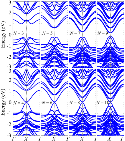
Finally, we calculate the electronic structures of PtN2 nanotubes. Figure 7 shows the PBE band structures of PtN2 nanotubes with the eight values. We notice that these band structures strongly depend on the values, similar to the dependence of the electronic structures of CNTs on their chiral indices.Dresselhaus et al. (1998) The PtN2 nanotubes with odd values are semiconducting with indirect PBE bandgaps of are 1.24, 0.87, 0.54, and 0.40 eV, for = 3, 5, 7, and 9, respectively. By contrast, the PtN2 nanotubes with even (4, 6, 8, and 10) are quasi-metallic with nearly the same tiny PBE direct band gaps of 0.07, 0.06, 0.08, and 0.08 eV, respectively. These different electronic structures of the PtN2 nanotubes with being odd and even may be because of their different symmetries. Due to the intense computational cost, we are able to calculate the HSE06 electronic structures for only two PtN2 nanotubes ( = 3 and 4). We find that the HSE06 bandgaps of the PtN2 with = 3 and 4 are 1.96 and 0.77 eV, respectively. Note that the PBE functional once again is inaccurate to describe the bandgaps of PtN2 nanotubes. This deficiency is worse for the nanotubes with even values. Assuming the trend of the PBE band gaps of PtN2 nanotubes holds for the HSE06 bandgaps, namely, the bandgaps of PtN2 nanotubes will decrease with increasing (odd) values and the range of tunable bandgaps is between 1.11 eV for single-layer PtN2 and 1.96 eV for the ( = 3) PtN2 nanotube. In contrast to narrow-gap CNTs and large-gap BNNTs,Blase et al. (1994); Matsuda et al. (2010) the wide range of tunable bandgaps are within the visible light spectrum, making PtN2 nanotubes promising 1D materials for optoelectronics applications.
IV Conclusions
In summary, by increasing the dimension of single-layer PtN2, we have predicted a more stable structure of bulk PtN2 with tetragonal AA-stacked layered structure using DFT calculations. This structure is energetically more favorable than the pyrite structure or single-layer PtN2, therefore resulting in a physically positive formation energy of the single-layer PtN2, which is otherwise negative if using the energy of the pyrite structure as the reference. Owing to the layered structure, our predicted bulk structure provides a promising source for mechanically exfoliated single-layer semiconducting PtN2, consisting of a pattern of type 2 pentagons. We also find that applying external pressure can lead to the phase transition between the pyrite and tetragonal layered structures of PtN2 and the transition pressures are about 20 and 15 GPa determined by the PBE and DFT-D3 methods, respectively. On the other hand, by reducing the dimension, we have predicted PtN2 nanotubes with tunable band gaps (by varying their sizes) within the visible light spectrum. Furthermore, wrapping single-layer PtN2 into nanotubes costs a comparable or smaller amount of energy in comparison to wrapping single-layer graphene and boron nitride into CNTs and BNNTs, respectively. The predicted PtN2 nanotubes may find applications in optoelectronics devices.
Acknowledgements.
We thank the start-up funds from Arizona State University. S. Lakamsani thanks the SCience and ENgineering Experience (SCENE) program and C. Price thanks the Fulton Undergraduate Research Initiative (FURI). This research used the computational resources of the Agave computer cluster at Arizona State University.References
- Haastrup et al. (2018) S. Haastrup, M. Strange, M. Pandey, T. Deilmann, P. S. Schmidt, N. F. Hinsche, M. N. Gjerding, D. Torelli, P. M. Larsen, A. C. Riis-Jensen, et al., 2D Materials 5, 042002 (2018).
- Ashton et al. (2017) M. Ashton, J. Paul, S. B. Sinnott, and R. G. Hennig, Physical review letters 118, 106101 (2017).
- Liu et al. (2018) Z. Liu, H. Wang, J. Sun, R. Sun, Z. Wang, and J. Yang, Nanoscale 10, 16169 (2018).
- Zhao et al. (2019) K. Zhao, X. Li, S. Wang, and Q. Wang, Physical Chemistry Chemical Physics 21, 246 (2019).
- Yuan et al. (2019) J.-H. Yuan, Y.-Q. Song, Q. Chen, K.-H. Xue, and X.-S. Miao, Applied Surface Science 469, 456 (2019).
- Wells (1991) D. Wells, The Penguin Dictionary of Curious and Interesting Geometry, Penguin books : Mathematics reference (Penguin Books, 1991).
- Yamanaka (1998) S. Yamanaka, Nature (London) 392, 580 (1998).
- Young et al. (2006) A. F. Young, J. A. Montoya, C. Sanloup, M. Lazzeri, E. Gregoryanz, and S. Scandolo, Physical Review B 73, 153102 (2006).
- Fu et al. (2009) H. Fu, W. F. Liu, F. Peng, and T. Gao, Physica B: Condensed Matter 404, 41 (2009).
- Yu et al. (2006) R. Yu, Q. Zhan, and X.-F. Zhang, Applied physics letters 88, 051913 (2006).
- Gou et al. (2006) H. Gou, L. Hou, J. Zhang, G. Sun, L. Gao, and F. Gao, Applied physics letters 89, 141910 (2006).
- Crowhurst et al. (2006) J. C. Crowhurst, A. F. Goncharov, B. Sadigh, C. L. Evans, P. G. Morrall, J. L. Ferreira, and A. Nelson, Science 311, 1275 (2006).
- Yu and Zhang (2005) R. Yu and X.-F. Zhang, Applied Physics Letters 86, 121913 (2005).
- Chen et al. (2007) Z. Chen, X. Guo, Z. Liu, M. Ma, Q. Jing, G. Li, X. Zhang, L. Li, Q. Wang, Y. Tian, et al., Physical Review B 75, 054103 (2007).
- Iijima (1991) S. Iijima, nature 354, 56 (1991).
- Bacsa et al. (1995) W. Bacsa, A. Chatelain, T. Gerfin, R. Humphrey-Baker, L. Forro, D. Ugarte, et al., Science 268, 845 (1995).
- Hamada et al. (1992) N. Hamada, S.-i. Sawada, and A. Oshiyama, Physical review letters 68, 1579 (1992).
- Koziol et al. (2007) K. Koziol, J. Vilatela, A. Moisala, M. Motta, P. Cunniff, M. Sennett, and A. Windle, Science 318, 1892 (2007).
- De Heer et al. (1995) W. A. De Heer, A. Chatelain, and D. Ugarte, science 270, 1179 (1995).
- Chen et al. (2005a) J. Chen, V. Perebeinos, M. Freitag, J. Tsang, Q. Fu, J. Liu, and P. Avouris, Science 310, 1171 (2005a).
- Zettl (1996) A. Zettl, Advanced Materials 8, 443 (1996).
- Pokropivny (2001) V. V. Pokropivny, Powder Metallurgy and Metal Ceramics 40, 485 (2001).
- Ivanovskii (2002) A. L. Ivanovskii, Russian Chemical Reviews 71, 175 (2002).
- Kresse and Furthmüller (1996) G. Kresse and J. Furthmüller, Phys. Rev. B 54, 11169 (1996).
- Perdew et al. (1996) J. P. Perdew, K. Burke, and M. Ernzerhof, Phys. Rev. Lett. 77, 3865 (1996).
- Grimme et al. (2010) S. Grimme, J. Antony, S. Ehrlich, and H. Krieg, The Journal of chemical physics 132, 154104 (2010).
- Dion et al. (2004) M. Dion, H. Rydberg, E. Schröder, D. C. Langreth, and B. I. Lundqvist, Physical review letters 92, 246401 (2004).
- Román-Pérez and Soler (2009) G. Román-Pérez and J. M. Soler, Physical review letters 103, 096102 (2009).
- Klimeš et al. (2011) J. Klimeš, D. R. Bowler, and A. Michaelides, Physical Review B 83, 195131 (2011).
- Blöchl (1994) P. E. Blöchl, Phys. Rev. B 50, 17953 (1994).
- Kresse and Joubert (1999) G. Kresse and D. Joubert, Phys. Rev. B 59, 1758 (1999).
- Monkhorst and Pack (1976) H. J. Monkhorst and J. D. Pack, Phys. Rev. B 13, 5188 (1976).
- Singh et al. (2015) A. K. Singh, K. Mathew, H. L. Zhuang, and R. G. Hennig, The journal of physical chemistry letters 6, 1087 (2015).
- Chen et al. (2010) W. Chen, J. Tse, and J. Jiang, Solid State Communications 150, 181 (2010).
- Mostaani et al. (2015) E. Mostaani, N. D. Drummond, and V. I. Fal’ko, Phys. Rev. Lett. 115, 115501 (2015).
- Novoselov et al. (2004) K. S. Novoselov, A. K. Geim, S. V. Morozov, D. Jiang, Y. Zhang, S. V. Dubonos, I. V. Grigorieva, and A. A. Firsov, science 306, 666 (2004).
- Le Page and Saxe (2002) Y. Le Page and P. Saxe, Phys. Rev. B 65, 104104 (2002).
- Mouhat and Coudert (2014) F. Mouhat and F. m. c.-X. Coudert, Phys. Rev. B 90, 224104 (2014).
- García et al. (2018) J. H. C. García, J. C. M. Hernandez, M. d. L. R. Peralta, A. Bautista-Hernandez, and A. E. Morales, Materials Research Express (2018).
- Liu et al. (2014) Z. Liu, D. Gall, and S. Khare, Physical Review B 90, 134102 (2014).
- Chen et al. (2005b) X.-J. Chen, V. V. Struzhkin, Z. Wu, M. Somayazulu, J. Qian, S. Kung, A. N. Christensen, Y. Zhao, R. E. Cohen, H.-k. Mao, et al., Proceedings of the National Academy of Sciences 102, 3198 (2005b).
- Chen et al. (2011) X.-Q. Chen, H. Niu, D. Li, and Y. Li, Intermetallics 19, 1275 (2011).
- Voigt (1928) W. Voigt, Lehrbuch der kristallphysik, Vol. 962 (Teubner Leipzig, 1928).
- Hill (1952) R. Hill, Proceedings of the Physical Society. Section A 65, 349 (1952).
- Perdew et al. (1992) J. P. Perdew, J. A. Chevary, S. H. Vosko, K. A. Jackson, M. R. Pederson, D. J. Singh, and C. Fiolhais, Phys. Rev. B 46, 6671 (1992).
- Kohn and Sham (1965) W. Kohn and L. J. Sham, Phys. Rev. 140, A1133 (1965).
- Ceperley and Alder (1980) D. M. Ceperley and B. J. Alder, Phys. Rev. Lett. 45, 566 (1980).
- Hornyak et al. (2008) G. L. Hornyak, H. F. Tibbals, J. Dutta, and J. J. Moore, Introduction to nanoscience and nanotechnology (CRC press, 2008).
- Gregoryanz et al. (2004) E. Gregoryanz, C. Sanloup, M. Somayazulu, J. Badro, G. Fiquet, H.-K. Mao, and R. J. Hemley, Nature materials 3, 294 (2004).
- Ivanovskii (2009) A. L. Ivanovskii, Russian Chemical Reviews 78, 303 (2009).
- Zhi et al. (2010) C. Zhi, Y. Bando, C. Tang, and D. Golberg, Materials Science and Engineering: R: Reports 70, 92 (2010).
- Chen et al. (2017) X. Chen, C. M. Dmuchowski, C. Park, C. C. Fay, and C. Ke, Scientific reports 7, 11388 (2017).
- Janas (2018) D. Janas, Materials Chemistry Frontiers 2, 36 (2018).
- Dresselhaus et al. (1998) G. Dresselhaus, S. Riichiro, et al., Physical properties of carbon nanotubes (World scientific, 1998).
- Blase et al. (1994) X. Blase, A. Rubio, S. Louie, and M. Cohen, EPL (Europhysics Letters) 28, 335 (1994).
- Matsuda et al. (2010) Y. Matsuda, J. Tahir-Kheli, and W. A. Goddard III, The Journal of Physical Chemistry Letters 1, 2946 (2010).