XXXX-XXXX
3]Institute for Cosmic Ray Research, The University of Tokyo, Kashiwa, Chiba, Japan 4]Earthquake Research Institute, University of Tokyo, Bunkyo-ku, Tokyo, Japan
5]Kanagawa University, Yokohama, Kanagawa, Japan
Air Shower Observation by a Simple Structured Fresnel lens Telescope with Single Pixel for the Next Generation of Ultra-High Energy Cosmic Ray Observatory
Abstract
Improved statistics and mass-composition-sensitive observation are required to clarify the origin of ultra-high energy cosmic rays (UHECRs). Inevitably in the future, the UHECR observatories will have to be expanded due to the small flux; however, the upgrade will be expensive with the detectors currently in use. Hence, we are developing a new fluorescence detector for UHECR observation. The proposed fluorescence detector, called cosmic ray air fluorescence Fresnel-lens telescope (CRAFFT), has an extremely simple structure and can observe the longitudinal development of an air shower. Furthermore, CRAFFT has the potential to significantly reduce costs for the realization of a huge observatory for UHECR research. We deployed four CRAFFT detectors at the Telescope Array site and conducted the test observation. We have successfully observed ten air-shower events using CRAFFT. Thus, CRAFFT can be a solution to realize the next generation of UHECR observatories.
F00, F03
1 Introduction
Since the discovery of cosmic rays in 1912 by V.F. Hess, cosmic rays over a wide range of energies have been observed. However, the origin of cosmic rays, especially those with energies above , has not yet been clarified. In this regard, understanding the UHECR energy spectrum, mass composition, and anisotropy is crucially important. AGASA AGASASpectrum reported that the energy spectrum of cosmic rays extends beyond without the Greisen-Zatsepin-Kuzmin (GZK) limit GZK , even though the energy spectrum of HiRes HiResSpectrum is consistent with the GZK cut-off. In recent years, the Pierre Auger Observatory (Auger) PAOSpectrum , and Telescope Array (TA) TASpectrum confirmed this energy spectrum, demonstrating a flux suppression consistent with the GZK limit. TA also reported that an intermediate-scale of anisotropy of cosmic rays with energies greater than exists in the northern sky, called as the hotspot TAHotspot . In addition, Auger reported that the direction of arrival of cosmic rays with energies above has a dipole structure PAODipole , indicating that the sources of such high-energy cosmic rays should be outside our galaxy. Ultra-high energy cosmic rays (UHECRs) with energies above and a light nucleus (e.g. a proton) can propagate with only a few degrees of deflection in the galactic magnetic field, which is a few micro gauss. As a result, it is expected that UHECR sources can be identified. Currently, HiRes and TA have reported that the composition of UHECRs above is dominated by or consistent with light components such as proton HiResComp2010 TAComp2018 . On the other hand, Auger has indicated transition in the composition, from a light to heavy component at energies above Auger2014 . However, TA and Auger data are in good agreement within the systematic uncertainties at the moment WGComp2016 . To understand UHECR composition and identify its sources, higher statistics and composition-sensitive observation are indispensable.
In the future, the expansion of UHECR observatories to obtain better statistics will be inevitable, because the flux of UHECR with energies above is as low as a few events per per year. To realize these inevitable upgrades with the detectors currently in use, the cost will inflate in proportion to the effective area’s extension. Therefore, cost reduction of detectors will be required. Hence, to help realize the required cost reduction, we have developed a cosmic ray air fluorescence Fresnel lens telescope (CRAFFT) based on the concept of a simple air fluorescence detector privitera . This concept is highly suitable for cost reduction to realize a huge ground array composed of fluorescence detectors which can observe air shower longitudinal developments. Other solutions, such as a simple fluorescence detector, to achieve a large effective area have also been proposed and are being studied. For example, the FAST project FAST is developing telescopes comprising a composite mirror and 8-inch Photomultiplier Tubes (PMTs). Other candidates including fluorescence detectors from space EUSO TUS POEMA are also under development. Herein, we report the development and trial results of CRAFFT, a novel fluorescence detector that is extremely simple and inexpensive for the next generation of large-scale UHECR observatories.
2 Cosmic Ray Air Fluorescence Fresnel lens Telescope (CRAFFT)
The fluorescence technique adopted by CRAFFT was originally studied in the 1960s. At that time, various fluorescence detectors were developed, then the detection of the fluorescence light from air showers succeeded by using Fresnel lens hara1970 . After that, not Fresnel lens but mirrors have been more adopted as light collectors for fluorescence detectors, of which Fly’s Eye was one of the first successful example flyseye . Currently, technological advancements have enabled easy achievement of large Fresnel lenses with high UV transmittance, high-sensitivity photon sensors, and Flash ADC (FADC). JEM-EUSO is one of the challenging project for UHECR observation developing a high resolution Fresnel lens telescope with large aperture and large field of view (F.O.V.) from space EUSO . On the other hand, we are trying to develop a simple structure fluorescence detector with a Fresnel lens for a huge ground array to observe UHECRs.
2.1 Fluorescence Technique
An air fluorescence detector measures scintillation light emitted from molecules in the atmosphere excited by energetic particles in extensive air showers that are induced by high-energy cosmic rays. The wavelength band of the scintillation light ranges from to with the peaks mainly at , and . Emitted light from an air shower is attenuated via Rayleigh and Mie scattering while passing through the atmosphere. These faint UV photons are gathered and concentrated at the focal point of a fluorescence detector.
A modern fluorescence detector can observe an air shower track using multi pixels such that TA fluorescence detector (FD) has 256 PMTs TAFD ; this allows the shower detector plane (SDP) to be determined. The geometry of air showers can be determined by the arrival-timing information of each pixel. When an air shower is stereoscopically observed by more than two fluorescence detectors at different sites, its geometry can be determined as the line of SDP intersection. In the case of a hybrid detector, such as TA or Auger, comprising fluorescence and surface detectors, the additional information of arrival timing or shower core position provided by the surface detectors can allow the geometry to be determined with an accuracy that is better than . Once the geometry of an air shower is determined, the amount of light emitted onto the shower axis, which is proportional to the energy loss of the shower particles, can be calculated by considering the atmospheric attenuation. Following this calculation, the primary energy of cosmic rays can be estimated calorimetrically.
In order to determine the air shower geometry, a single-pixel Fresnel lens telescope such as CRAFFT detector records time profile of fluorescence photons from the air shower using FADC together with at least two more detectors deployed separately with a spacing of . Without the information of scintillation detector or water Cherenkov detector array, the geometry can be determined by arrival time information of photons. Once the geometry is determined, the longitudinal development of energy deposit as a function of atmospheric depth along the shower track can be reconstructed. Then, the time profile of FADC considering the reconstructed longitudinal development can be simulated. Using the simulated FADC time profile, the shower geometry is fitted again to reproduce the recorded FADC time profile. By the repetition of the above procedure, the accuracy of the geometry and the longitudinal development will be improved as a method of the profile constrained geometry fit technique adopted by the Fly’s Eye experiment PCF . Then, the energy and the can be determined.
The effective distance of a single-pixel Fresnel lens fluorescence detector with aperture and F.O.V. in which air showers of can be triggered is estimated to be up to by the simulation tameda2016 . Therefore, single-pixel FDs will be deployed as a huge array of a triangle lattice with spacing privitera .
2.2 Detector configuration
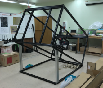
The structure of the CRAFFT detector is very simple, which makes it cost-effective and easy to deploy. Table 1 lists the main components of the detector. Figure 1 shows the structural design of the CRAFFT detector. The CRAFFT detector’s light collector is a Fresnel lens, which is made of UV-transmitting acrylic plastic, with a focal length of . At the focal point, an 8-inch PMT with a UV-transmitting filter is mounted. The PMT signal is recorded by the 80-MHz sampling 12-bit FADC board with field-programmable gate array (FPGA).
| Component | Product |
|---|---|
| Fresnel lens | NTKJ, CF1200-B |
| UV-transmitting filter | Hoya, U330 |
| Photomultiplier tube | Hamamatsu, R5912 |
| HV power supply | CAEN, N1470AR |
| HV divider | (special order) |
| FADC board | TokushuDenshiKairo, Cosmo-Z |
| Low pass filter | Mini Circuit, BLP-15+ |
| Amplifier | LeCroy, MODEL 612AM |
| Structure | YUKI, anodized T-slotted aluminum extrusions |
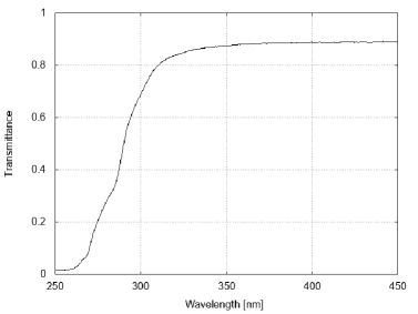
The focal length, effective aperture, dimensions, and pitch of the Fresnel lens are , , width , length , thickness and , respectively. The material of the Fresnel lens is acrylic plastic (Mitsubishi Chemical, ACRYLITE 000) and its transparencies is shown in Fig. 2 on the left. The scattering loss caused by the fine pitch of Fresnel lens is estimated 1.5% for the incident light with the angle of by ray tracing simulation.
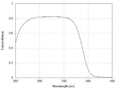
To reduce night sky background light in the visible range that does not contribute to the signal, a UV-transmitting filter of the range of is used. The filter is flat, and its dimensions are width , length and thickness . The transparency is shown in Fig. 2 on the right.
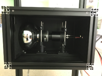
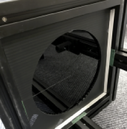
The photon sensor of the CRAFFT detector is an 8-inch large photocathode area PMT with a D type socket of a DC coupling with a negative high voltage power supply (E7694, Hamamatsu). The spectral response and the peak wavelength of the PMT are from to and . The photocathode and window material are bialkali and borosilicate glass, respectively. The photon entrance window is a spherical surface; thus, for this test observation, we use a spatial filter of diameter to cut the incident light at an angle of more than to reduce the ambiguity of detection efficiency at the periphery of the photon entrance windows (Fig. 4). The quantum efficiency at and the typical gain with of the PMT are and , respectively.
We use a high-voltage power supply that is controlled via a network to ensure that the Data acquisition (DAQ) system of CRAFFT can be controlled remotely.
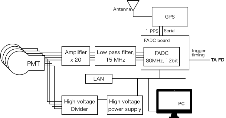
The signal from air showers is so faint that we use amplifier to amplify the signal and low pass filter to reduce the high frequency night sky background. The signal from the PMT is digitized and recorded by the FADC board on which Linux is available with Zynq. Zynq is a FPGA on which We can implement our own trigger algorithm now we are developing. The sampling rate and resolution of the Cosmo-Z are and , respectively. We can time events with precise time stamps using a GPS module (Linx Technologies Inc. EVM-GPS-FM), which provides 1 pulse per second as well as time information.
For the frame of the detector, T-slotted aluminum extrusions, that are black anodized to reduce light reflection, are used. Aluminum extrusions are easy-to-build and modify; hence, this a reasonable choice for the prototype test. To shield stray light and protect the components inside, the detector is covered by an thick steel plate. During daytime, we pull down the roll curtain between the lens and the PMT to prevent incident light from the sun.
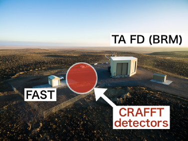
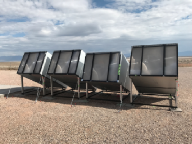
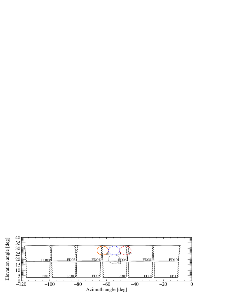
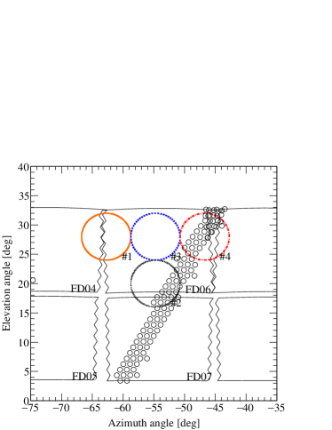
In October 2017, we deployed four CRAFFT detectors next to the fluorescence detector station at the Black Rock Mesa site of the TA experiment in Utah U.S. (Fig. 3). The F.O.V. of each detector was , limited by the spatial filter (Fig. 4). The elevation angles of the three detectors were and that of the other detector was . In this observation, we optimized the arrangement of the detectors to observe relatively low-energy air showers because the priority was to detect as many air shower events as possible. The F.O.V. of the four detectors corresponded to the 6th fluorescence detector of TA, as shown in Fig 5. The upper center and lower detectors observe the vertical laser from the TA Central Laser Facility (CLF) tomida . The remaining upper-viewing two detectors observe at an angle east or west from the center detector.
3 Observation
In 2017, we conducted a test observation for ten days from November 9 to November 23, when the TA FD was operating. The total observation time was 63.4 h.
We operated CRAFFT remotely from the control room of the TA FD at the Black Rock Mesa site. Figure 6 shows the block diagram of the electronics and DAQ system of CRAFFT. TA FDs recognize air shower events every and generate trigger timing pulses that are distributed from the front panel of trigger electronics tameda . We used a trigger timing signal from TA FD for data collection. We measured the relative gain of the telescopes, including the transparency effect, for both the lens and the UV filter, using a UV LED mounted on the lens surface. We regulate the applied voltage of PMT to adjust gain while measuring the LED light. As a result, we adjusted the gain of each telescopes within 20%. In this observation, we acquired 456,727 events. We searched air shower candidate events from all 456,727 data points recorded by CRAFFT. Most of the data did not include a signal because CRAFFT recorded the data using the trigger pulse from TA FD, the F.O.V. of which is about ten times larger than that of the CRAFFT detector. First, we selected the data with significant signals against the background. In addition, we excluded the CLF events that could easily identified from the time stamps. Figure 7 shows an example of a CLF event. Moreover, air plane events were also removed using a pulse width that is much wider than that of typical air shower events. Next, we selected the events with significant signals registered by more than two CRAFFT detectors. After this selection process, we obtained 6,600 event candidates. Finally, we extracted signals like air shower event via eye scanning while considering pulse width and height. We found ten apparent air shower events as a result of having compared those signals with corresponding TA Signals.
| Number of acquired data | 456,727 |
|---|---|
| Number of event candidate | 6,600 |
| Number of clear air shower event | 10 |
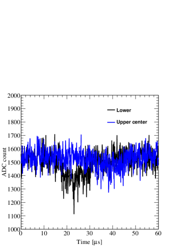
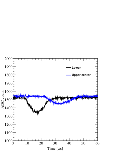
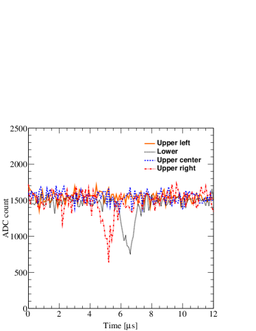
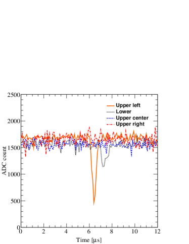
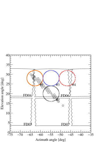
Figure 8 shows some typical events that we successfully observed. The left panels of Fig. 8 show waveforms of an air shower fluorescence signal recorded by CRAFFT. The right panels show the corresponding event displays of TA FD. As shown in Fig. 8, we successfully observed air shower events that were also identified as air shower events by the TA FD.
[a] 2017/11/11 05:59:54.835620750
[b] 2017/11/15 06:16:57.922469950
4 Discussion
We are developing a simple Fresnel lens FD, named CRAFFT, for UHECR observation. We deployed four CRAFFT detectors at the TA site and performed test observations. We acquired ten air shower events. We successfully demonstrated that UHECR can be observed using CRAFFT, which has a simple structure and an economic detector comprising only commercial products. This can be an attractive option for application in next generation UHECR observatories. In the case of a reflecting telescope especially for air shower observation, a large phototube cluster can be an obstacle to screen incident lights. On the other hand, all of incident lights can be focused at the focal plane with a refracting telescope. Therefore, a refracting telescope can be smaller than a reflecting telescope to achieve the same light collection efficiency. Additionally, it is much easier to extend the field of view by enlargement of the focal plane. The structure of a refracting telescope is very simple and compact so that all the component can be covered easily to keep detectors clean. This is good for easy maintenance. From these points, it is expected to impart the advantage of lower cost than ever.
FDs previously used for UHECR observation are expensive due to their strong structure required to support a large composite mirror system and the multi-channel DAQ system. Additionally, detectors must be covered by a building. In contrast, a refracting telescope using a Fresnel lens with a single-pixel phototube, such as the CRAFFT detector, possesses a simple structure. Thus, the cost reduces by more than ten times than that of the previous detectors. Moreover, the CRAFFT detector is easy to deploy and can be installed without a hut as all of its components can be covered by the structure alone due to its compactness.
We successfully demonstrated that a single-pixel Fresnel lens FD can be used for UHECR detection. For future work, we plan for stereo or multiple observations to establish a method to reconstruct geometry using CRAFFT. We believe that the current configuration of CRAFFT can be further optimized. We will also attempt the use of multiple pixels to improve or double lenses to extend the F.O.V., and reduce the cost per view. CRAFFT is a promising detector that may significantly contribute to the realization of next-generation UHECR observatories, post TA4 tax4 or AugerPrime augerprime .
Acknowledgment
This work was supported by the JSPS KAKENHI Grant Numbers 25610051 and JP16K17710. This work was partially carried out by the joint research program of the Institute for Cosmic Ray Research (ICRR), The University of Tokyo. This study was also supported by the Earthquake Research Institute The University of Tokyo Joint Usage/Research Program. The Telescope Array Collaboration supported CRAFFT as an associated experiment and allowed us to use TA equipments and FD event displays. We wish to thank the staffs at the University of Utah, especially Prof. J.N. Matthews.
References
- (1) M. Takeda et al., Phys. Rev. Letters 81, 1163-1166 (1998).
- (2) K. Greisen, Phys. Rev. Lett. 16, 748 (1966); G.T. Zatsepin and V.A. Kuz’min, JETP Lett. 4, 78 (1966).
- (3) R.U. Abbasi et al., Astropart. Phys. 23, 157-174 (2005).
- (4) The Pierre Auger Collaboration, Physics Letters B 685, 239–246 (2010).
- (5) T. Abu-Zayyad et al., The Astrophysical Journal Letters 768, 1 (2013).
- (6) R.U. Abbasi et al., The Astrophysical Journal Letters 790, 2 (2014).
- (7) The Pierre Auger Collaboration, Science 357 no.6537, 1266-1270 (2017).
- (8) R.U. Abbasi et al., Physical Review Letters 104, 161101 (2010).
- (9) R.U. Abbasi et al., The Astrophysical Journal 858, 76 (2018).
- (10) A. Aab et al., Physical Review D 90, no.12, 122005 (2014).
- (11) R.U. Abbasi et al., Proceedings of international symposium for Ultra-High Energy Cosmic Rays, 010016 (2016)
- (12) P. Privitera et al., Internal Symposium on Future Directions in UHECR Physics (2012).
- (13) D. Mandat et al., Journal of Instrumentation 12 T07001 (2017).
- (14) M. Casolino, Proceedings of the 35th International Cosmic Ray Conference, 370 (2017).
- (15) P. Klimov et al. Proceedings of the 35th International Cosmic Ray Conference, 1098 (2017).
- (16) A.V. Olinto et al., Proceedings of the 35th International Cosmic Ray Conference, 542 (2017).
- (17) T. Hara et al., Acta Phys. Acad. Sci. Hungaricae, 29:369 (1970).
- (18) H.E. Bergeson, G.L. Cassiday, T.W. Chiu, D.A. Cooper, J.W. Elbert, E.C. Loh, D. Steck, W.J. West, J. Linsley, and G.W. Mason, Phys. Rev. Lett. 39, 847 (1977).
- (19) H. Tokuno et al., Nucl. Instr. and Meth. A 676, 54-65 (2012).
- (20) T. Abu-Zayyad, PhD thesis, University of Utah (2000).
- (21) Y. Tameda et al., Proceedings of 2016 International Conference on Ultra-High Energy Cosmic Rays, 011037 (2018).
- (22) Y. Tameda et al., Nucl. Instr. and Meth. A 609, 227-234 (2009).
- (23) T. Tomida et al., Nucl. Instr. and Meth. A 654, 653-660 (2011).
- (24) E. Kido et al., Proceedings of the 35th International Cosmic Ray Conference, 386 (2017).
- (25) Z. Zong et al., Proceedings of the 35th International Cosmic Ray Conference, 449 (2017).