Full proximity treatment of topological superconductors in Josephson-junction architectures
Abstract
Experiments on planar Josephson-junction architectures have recently been shown to provide an alternative way of creating topological superconductors hosting accessible Majorana modes. These zero-energy modes can be found at the ends of a one-dimensional channel in the junction of a two-dimensional electron gas (2DEG) proximitized by two spatially separated superconductors. The channel, which is below the break between the superconductors, is not in direct contact with the superconducting leads, so that proximity coupling is expected to be weaker and less well controlled than in the simple nanowire configuration widely discussed in the literature. This provides a strong incentive for this paper which investigates the nature of proximitization in these Josephson junction architectures. At a microscopic level we demonstrate how and when it can lead to topological phases. We do so by going beyond simple tunneling models through solving self-consistently the Bogoliubov-de Gennes equations of a heterostructure multicomponent system involving two spatially separated -wave superconductors in contact with a normal Rashba spin-orbit-coupled 2DEG. Importantly, within our self-consistent theory we present ways of maximizing the proximity-induced superconducting gap by studying the effect of the Rashba spin-orbit coupling, chemical potential mismatch between the superconductor and 2DEG, and sample geometry on the gap. Finally, we note (as in experiment) a Fulde-Ferrell-Larkin-Ovchinnikov phase is also found to appear in the 2DEG channel, albeit under circumstances which are not ideal for the topological superconducting phase.
I Introduction
There has been much excitement in the literature over the possibility of observing one-dimensional (1D) topological superconductivity which involves a single 1D wire Lutchyn et al. (2010); Oreg et al. (2010) leading to accessible Majorana zero modes. Because of fluctuation effects in low dimensions, there can be no intrinsic superconductivity so that the focus is on proximitized superconductors. Studies of these wires and their applications towards quantum computation have led to a very extensive literature Alicea (2012); Leijnse and Flensberg (2012); Stanescu and Tewari (2013); Beenakker (2013); Elliott and Franz (2015); Sarma et al. (2015); Aguado (2018); Lutchyn et al. (2018). In a broad sense, there are two general configurations for proximitized 1D topological superconductors. These are associated with “nanowires” in direct contact with superconducting hosts as well as the recently proposed planar Josephson junction Pientka et al. (2017); Hell et al. (2017). The latter contains a proximitized 1D channel in the two-dimensional electron gas (2DEG) just below the break between the two superconductors. This configuration is less widely studied, but there is evidence based on zero-bias conductance peaks Sengupta et al. (2001); Law et al. (2009); Flensberg (2010); Prada et al. (2012), as in the simple nanowires Mourik et al. (2012); Rokhinson et al. (2012); Deng et al. (2012); Das et al. (2012); Churchill et al. (2013); Finck et al. (2013); Albrecht et al. (2016); Gül et al. (2018); Chen et al. (2017); Deng et al. (2016); Suominen et al. (2017); Nichele et al. (2017); Zhang et al. (2018, 2017); Sestoft et al. (2018); Deng et al. (2018); Laroche et al. (2019); van Veen et al. (2018); de Moor et al. (2018); Grivnin et al. (2018); Vaitiekėnas et al. (2018), that topological superconductivity has been experimentally observed Ren et al. (2019); Fornieri et al. (2019).
Indeed, the planar junctions have a notable strength relative to the nanowires. The phase difference between the two superconductors provides an alternative knob (beyond the Zeeman field) to tune the system into the topological phase Pientka et al. (2017); Hell et al. (2017). In ideal (i.e., transparent) systems, when the superconducting phase difference is , the topological phase can be achieved for rather small Zeeman fields. However, compared to the proximitized nanowire, the planar Josephson junction architecture is associated with weaker and less well-controlled proximitization, as the 1D channel in the junction is not in direct contact with the host superconductors.
This leads to the central goal of this paper which is to quantify this somewhat indirect form of proximitization and to optimize its effectiveness. We focus on a well-studied substrate: the 2DEG which has moderately strong Rashba spin-orbit coupling (SOC). Our calculations go beyond the simple tunneling models McMillan (1968a, b); Sau et al. (2010); Stanescu et al. (2010); Potter and Lee (2011) of the proximity effect by solving the full Bogoliubov-de Gennes (BdG) equations of a multicomponent system with self consistency 111Although not all of the results presented in this paper are fully self-consistent, we have checked in a few cases that increasing the number of iterations only very slightly modifies our results.. In our full proximity model, the host superconductors are treated as a participating component rather than as a passive source of Cooper pairing. The effectiveness of proximitization is quantified via the strength of the induced pairing amplitude, . Maximizing this pairing amplitude is the goal as it is associated with a large gap in the dispersion. This, in turn, leads to more localized and thus more stable Majorana modes. In this paper we characterize the deleterious effects on which can come from any of the following: SOC, enhanced substrate thickness, enhanced channel width, and chemical potential differences (between the host superconductors and the 2DEG). Importantly, our findings which are obtained using a fully self-consistent theory, can provide guidance in determining the optimal range of experimental parameters for the topological protection of Majorana modes.
While not essential to the topological superconductivity, a relevant complement to these studies relates to a very elusive state of matter, the Fulde-Ferrell-Larkin-Ovchinnikov (FFLO) Fulde and Ferrell (1964); Larkin and Ovchinnikov (1964) phase which we also observe in these planar junctions. This appears to be consistent with recent experiments which have reported that this otherwise rare phase of superconductivity is realized in proximitized superconductors Hart et al. (2017); Chen et al. (2018). For the situation here, it can be viewed as arising from a “second-order proximitization” process. We trace its origin to the fact that the channel makes little direct contact with the superconductors, unlike the rest of the proximitized 2DEG. Thus, in this region of the junction, the pairing amplitude is reduced and the effective small pairing gap is freer to oscillate in response to an applied Zeeman field. We finally note that this FFLO phase is most apparent in relatively wide junctions where the gap is smaller and it is thus unfavorable for stabilizing a topological phase.
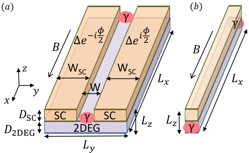
The two generic types of proximitized 1D topological superconductors are illustrated in Fig. 1. The Majorana zero-modes (indicated by ) appear at the ends of the junction where they are most easily manipulated. In structures as shown in Fig. 1(a), the substrate is a Rashba spin-orbit-coupled 2DEG. Figure 1(b) shows a more successful variant of these hybrid structures which involve semiconducting nanowires (although chains of magnetic atoms Nadj-Perge et al. (2014); Klinovaja et al. (2013); Nadj-Perge et al. (2013); Li et al. (2014, 2016); Brydon et al. (2015); Hui et al. (2015) and topological insulators Fu and Kane (2008); Xu et al. (2015); Sun et al. (2016) have also been considered).
One should appreciate that to design topological superconductors without proximitization, say by doping a topological insulator Fu and Berg (2010); Sasaki et al. (2011), there is less control in engineering the appropriate combination of SOC, Zeeman field, and band structure in the presence of sufficiently strong pairing attraction. The existence of these intrinsic topological superconductors is still controversial Peng et al. (2013) so that, currently, proximity-induced superconductivity appears to be an essential tool. Because it is so essential it is imperative to understand it better, not just in the immediate interface, which has been studied Potter and Lee (2011); Stanescu et al. (2010); Sau et al. (2010), but well into the depth of a hypothesized topological superconductor Chiu et al. (2016); Stanescu and Das Sarma (2013).
I.1 Overview and Outline
It is useful to quantitatively characterize the Josephson-junction-based topological superconductors we consider here in terms of the size of the energy gap, , associated with the proximitized 2DEG. The quantity depends on the junction geometry and materials parameters. It varies with the junction thickness, the strip width, the SOC and chemical potential difference between the host superconductors and the 2DEG. Equally important is its dependence on the external parameters which control topological phases: the Josephson-junction phase difference and the Zeeman field . This field enters in two different ways; it affects the gap opening and closing processes associated with topological phase transitions in a Josephson junction. It also affects the coupling at each separate interface between the host superconductor and the 2DEG substrate. Increasing in the 2DEG inhibits proximitization.
It is convenient, then, to isolate these processes by writing
| (1) |
This states that the energy gap in the presence of Zeeman and superconducting phase difference, , depends directly on a proximity-induced gap , (which is deduced in the absence of any Zeeman field, or phase bias ), times a multiplicative function, , which represents (dominantly) the topological characteristics of the junction.
In the topological region, the parameter is, thus, a crucial parameter, as its inverse characterizes the Majorana localization length. The smaller this length, the more localized are the Majorana modes. The localization of the Majoranas is, then, optimized when the proximity gap is maximal. Understanding this is one of the central contributions of our paper.
We now present a brief outline. Section II of the paper discusses the theoretical model, i.e., the Hamiltonian of the planar Josephson junction. In Sec. III, we give a discussion of the self-consistent BdG approach used to solve for the energy dispersion and proximity-induced gap. In Sec. IV we study a simple tunneling model of the superconducting proximity effect in which the junction is converted to a lower dimension by integrating out the host superconductors. Section V focuses on numerical results from our full-proximity model for the proximity gap where is the spectral gap calculated for junctions in the absence of Zeeman field and superconducting phase difference. Here we separately discuss the role of SOC, chemical potential mismatch, and 2DEG thickness on . The symmetry class of the planar Josephson junction is addressed in Sec. VI. In Sec. VII we present the topological phase diagram as a function of in-plane Zeeman field and superconducting phase bias for different chemical potential mismatch. We further show the evolution of the energy spectrum across the topological phase transition. Section VIII presents a brief discussion of how FFLO superconducting phase is established, in the presence of an in-plane Zeeman field along the junction. More details of this elusive FFLO phase are presented in Appendix A. Finally, we summarize our conclusions in Sec. IX.
II Theoretical Model
We consider a Josephson junction made from a Rashba spin-orbit-coupled 2DEG in contact with two spatially separated superconductors and subjected to an in-plane magnetic field along the junction as shown in Fig. 1(a). This system was proposed recently Pientka et al. (2017); Hell et al. (2017) as a new platform to realize topological superconductors. In this setup, the transition between the trivial and topological phases can be tuned by varying either the applied in-plane magnetic field along the junction or the phase difference between the two superconductors. In an ideal situation, the interplay between these two independent knobs enables a lower critical field for the topological transition to be achieved when the superconducting phase difference is tuned near . This Zeeman- and phase-tunable topological transition was demonstrated in recent experiments carried out by two independent groups Ren et al. (2019); Fornieri et al. (2019).
II.1 Hamiltonian
We begin by writing down the “normal” component (in the absence of superconducting pairing) of the Hamiltonian as
| (2) | |||||
where () is the annihilation (creation) operator of an electron with spin . In Eq. (II.1), is the identity matrix and are the Pauli matrices acting on the spin degree of freedom. Here, represents the real space momentum operator, is the effective electron mass, and is the chemical potential. The chemical potentials are taken to be
| (3) |
where and are the chemical potentials of the superconductor and 2DEG, respectively. Throughout this paper, we work in units where , , and which gives the Fermi momentum of the 2DEG, . The widths of the superconductors and the junction (along the direction) are denoted by and , respectively [see Fig. 1(a)]. In this paper we consider the width of the superconducting leads , where is the superconducting coherence length. We further denote the thicknesses of the superconductors and the 2DEG by and , respectively. Note that for numerical simplicity, we introduce an insulator in between the superconductors with the same thickness as the superconductor above the 2DEG. Its chemical potential is taken to be very negative (), so that it behaves essentially as a vacuum.
The Zeeman energy is due to the applied in-plane magnetic field along the junction ( direction) with being the Lande factor and being the Bohr magneton. Except when indicated otherwise, the Zeeman energy is assumed to be zero in the host superconductor and insulator but taken to be constant throughout the 2DEG (, where is the Zeeman energy of the 2DEG directly below the superconducting leads and is the Zeeman energy of the 2DEG in the junction). We justify this assumption by noting that the Lande factor for the superconductor ( for Al) is much smaller than the Lande factor for the semiconductor ( for InAs) Winkler (2003); Mikkelsen et al. (2018); Antipov et al. (2018).
An important parameter which appears throughout this paper is which characterizes the strength of the SOC in the 2DEG. The SOC strength is zero in the superconductors and insulator but finite in the 2DEG, i.e.,
| (4) |
This is a realistic representation Sticlet et al. (2017); Stanescu and Das Sarma (2017) of the well-studied situation of a spin-orbit-coupled semiconductor proximitized by an -wave superconductor.
So far we have described a noninteracting system. Now, let us include the superconducting pairing term in the Hamiltonian, which is given by
| (5) |
We assume that the system is translationally invariant along the direction and finite in both and directions. Because the system is translationally invariant along the direction, we can write the Hamiltonian in the Nambu basis as
| (6) |
where the BdG Hamiltonian is given by
| (7) |
Here the Pauli matrices and act in the spin and particle-hole subspace, respectively, with . The superconducting pairing potential, , arises microscopically from the attractive interactions which are only present in the host superconductors:
| (8) |
where is the coupling function within the parent superconductors:
| (9) |
Here, is the attractive coupling constant, and is the phase difference between the two superconductors. Applying a Bogoliubov transformation, Halterman and Valls (2001); Wu et al. (2012), where is the Bogoliubov quasiparticle annihilation (creation) operator at an energy , we then obtain the pair amplitude
| (10) |
with being the temperature. The Debye frequency provides an energy cutoff in Eq. (II.1). Note that, through the proximity effect, the pair amplitude in the 2DEG is nonzero even though there is a vanishing order parameter, , reflecting the fact that there. The superconducting pairing potential is obtained by solving the BdG Hamiltonian self-consistently as explained in the next subsection.
III Self-Consistent BdG Equation
We obtain the pair amplitude [Eq. (II.1)] by numerically solving the BdG eigenvalue problem following the scheme developed in Refs. Halterman and Valls (2001); Wu et al. (2012, 2017, 2018). The scheme is based on the idea of diagonalizing the BdG Hamiltonian [Eq. (II.1)]. The resulting BdG equation reads
| (11) |
where the wave function is given by
| (12) |
with the boundary condition at , and and subject to the self-consistency equation [Eqs. (8)- (II.1)]. To this end, we expand both the matrix elements and the eigenfunctions in terms of a Fourier basis. Specifically, the quasiparticle () and quasihole () wavefunctions are given by
| (13a) | |||||
| (13b) | |||||
For definiteness, we set the smallest length scale to be of the order of where is the Fermi momentum of the 2DEG.
General matrix elements are similarly expanded in terms of the same Fourier series. For example, we define the matrix elements of an operator to be
| (14) | |||||
In this way all terms in the BdG Hamiltonian can be expanded in this basis set. What we have accomplished in this procedure is to successfully transform a set of differential equations into an algebraic matrix eigenvalue problem.
Having recast the Hamiltonian in the basis given in Eq. (13), we then solve for the pair amplitude using Eqs. (8)-(II.1) from the wavefunction [Eq. (12)] obtained by diagonalizing the Hamiltonian [Eq. (11)]. The calculated pair amplitude is then used to get a new wavefunction . This self-consistent procedure is carried out repeatedly until convergence is reached. The first iteration generally contains the central physics. Because of the numerical complexity of the full-proximity model and the many parameter sets we address, in many plots we restrict ourselves to the first iteration; in test cases we have confirmed that higher iterations introduce changes in the solution of only a few percent. Throughout this paper, the pair amplitude is calculated by setting the parent superconductor pair potential, , Debye frequency , and temperature in Eq. (II.1).
IV Tunneling approximation to proximitization
The above more powerful procedure has not been widely applied; rather the literature focus has been on an approximate treatment of proximitization. The approximate approach builds on earlier work by McMillan McMillan (1968a, b), who introduced a perturbative treatment of a tunneling Hamiltonian for a single NS junction which consists of a normal metal in proximity to a superconductor. This treatment was later extended by Refs. Sau et al. (2010); Stanescu et al. (2010); Potter and Lee (2011) to deal with a spin-orbit-coupled electron gas or a topological insulator in proximity with a superconductor. In this section we use and to represent the 2DEG and superconductor, respectively; both are considered to be sufficiently thin so that any spatial variations within each can be ignored. The Hamiltonian for the SC/2DEG heterostructure can be written as
| (15) |
Here, is the Hamiltonian of the superconductor () and 2DEG (), respectively, and the tunneling Hamiltonian is given by
| (16) |
where is the annihilation operator in the or side of the interface for an electron with momentum and spin . This tunnel Hamiltonian conserves momentum parallel to the interface but changes the transverse momentum perpendicular to the interface.
In this approach one derives the proximity-induced superconductivity by integrating out the superconducting term in Eq. (15) and calculating the surface self-energy due to the electron tunneling between the 2DEG and superconductor.
Assuming the density of states to be weakly dependent on energy, the surface self-energy can be calculated to be Sau et al. (2010); Stanescu et al. (2011)
| (17) |
where the density of states is evaluated at the Fermi energy of the 2DEG and is the proximity-induced shift in the chemical potential of the 2DEG. We can now incorporate this self-energy into the strong-coupling form Nambu (1960); Eliashberg (1960); Schrieffer (1964) of the 2DEG Green’s function, where we have
| (18) |
Here,
| (19) |
is the reduced quasiparticle weight due to the virtual propagation of electrons in the superconductor with being the effective coupling between the 2DEG and superconductor. This quasiparticle weight can be viewed as the fraction of time that a propagating electron spends on the superconducting side of the interface. The proximity-induced superconducting pairing potential in the 2DEG is then given by
| (20) |
Having solved for , we now solve for the renormalized superconducting pairing potential in the superconductor. Similar to Eq. (IV), the self-energy of the superconductor due to electron tunneling from the 2DEG is given by
| (21) |
Substituting this into the strong-coupling form of Green’s function of the superconductor, we have
| (22) |
where
| (23) |
Thus, the renormalized superconducting pairing potential in the superconductor is given by
| (24) |
where is the gap of an isolated superconductor. Note that the subscripts in the above equations refer to the quantities in the 2DEG () and superconductor (), respectively. The coupled gap equations [Eqs. (20) and (24)] reflect the fact that proximitization is a two-way process. This leads to a pairing gap in a normal material and at the same time it renormalizes the excitation gap in the host superconductor.
IV.1 Relation to the standard effective model
In the literature, it is rather common to ignore the corrections in the host superconductor and assume but we will see in the full proximitization theory that this is not generally a good assumption. Also important is that in the more general situation, all pair amplitude parameters vary continuously across the system.
With this simplification, the above analysis is the basis for the so-called “effective model” which is described as having integrated out the host superconductor. In the effective model, the Hamiltonian of the 2DEG is given by Pientka et al. (2017); Hell et al. (2017)
| (25) |
where is the proximity-induced pairing potential in the 2DEG which is obtained after integrating out the superconductors. This is given by
| (26) |
where is chosen phenomenologically.
V Understanding the proximity-induced gap
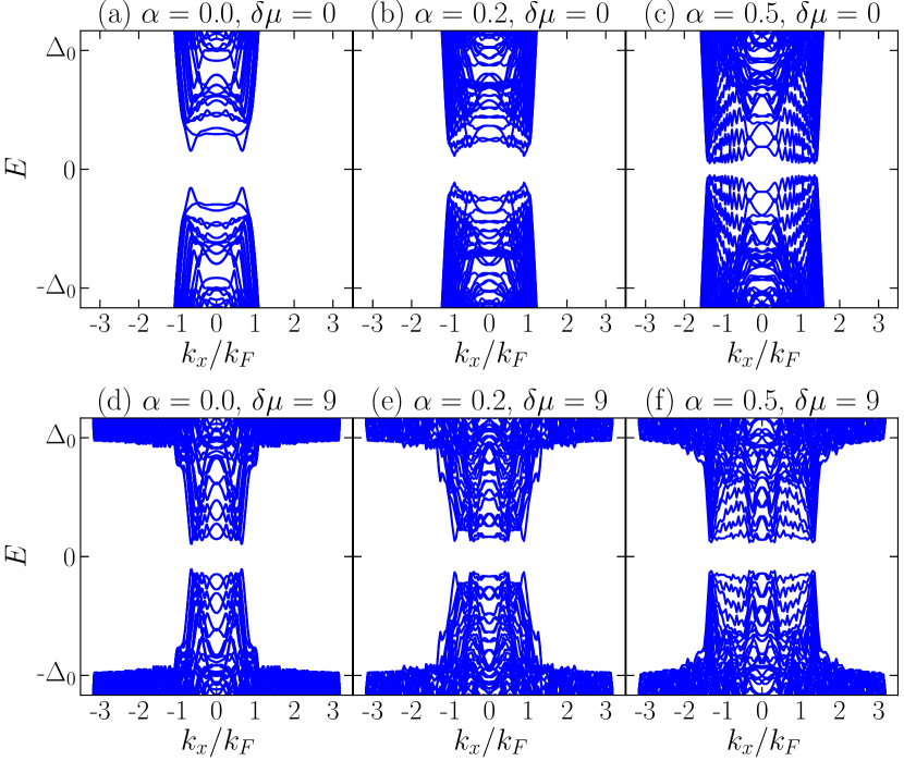
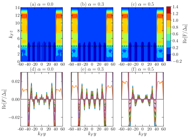
We turn now to numerical results for obtained from our full proximitization studies. Although we begin with the limit of zero magnetic field, it is useful to understand how the magnetic field affects the separate proximitization processes at each of the two interfaces between the 2DEG and the host superconductor. To do this we compare two kinds of Josephson-junction configuration: The first junction has the Zeeman field confined to the channel in the 2DEG between the two superconductors [Figs. 2(a) and 2(c)] and the second junction has the field applied uniformly in the 2DEG substrate [Figs. 2(b) and 2(d)], as in experiments.
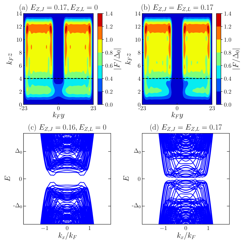
The upper panels in Fig. 2 present contour plots of the pair amplitudes and the lower plots show the energy dispersions. One can see that a magnetic field below the superconductors has very little effect on the parent superconductors but, as expected, it inhibits proximitization and does decrease the pair amplitude and energy gap in the 2DEG. Fortunately with the planar Josephson-junction design, we can tune the phase difference towards where the critical field for the transition into the topological phase is smaller such that there is still a substantial gap present when the system is in the topological phase.
In the remainder of this section, we will address how to optimize the proximity gap at . By dropping the Zeeman field and junction phase bias, we are establishing how to select materials as well as geometric parameters.
V.1 Effects of variable spin-orbit coupling and chemical potential mismatch
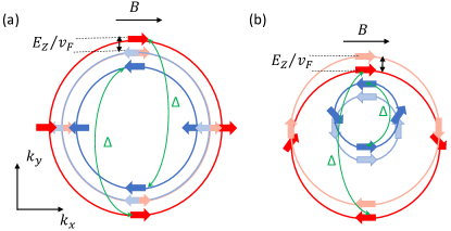
Since SOC plays an important role, it should be noted that there is no consensus in the literature about how SOC interacts with proximitization. It has been argued that larger SOC is beneficial Potter and Lee (2011). We find here, that in the absence of a magnetic field, the effects of SOC on the proximity-induced gap are strongly tied to the size of the chemical potential difference between the superconductors and the 2DEG. This can be understood in large part because of a mismatch in the Fermi momenta of the bands in the superconductors with those of the spin-orbit-coupled 2DEG.
This mismatch is illustrated in Fig. 3. Here the left panel (a) shows the superposed normal-state dispersions for the case where the superconductor and spin-orbit-coupled 2DEG have the same chemical potential and the right panel (b) is for the case where the chemical potential in the superconductor is much larger than that in the 2DEG, as is more often the case. The principal conclusion from panel (a) is that there are many bands in 2DEG which have little Fermi momentum overlap (because of the shift due to SOC in the 2DEG) with bands in the superconductors; one can anticipate that this mismatch increases as the SOC becomes larger. This is in contrast to panel (b) where all bands in the 2DEG have their Fermi momenta close to those in the superconductor. Here the deleterious effects of SOC on the proximity-induced gap will be less apparent.
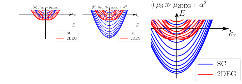
We summarize this by noting that the dependence of the proximitized gap on the SOC strength is weaker for the case where the superconductor chemical potential is larger than the 2DEG chemical potential. This is because a superconductor with a larger chemical potential has more occupied subbands. As a result, for an incident electron coming from the 2DEG with transverse momentum normal to the interface, there is an electron from one of the subbands in the superconductor with momentum which is close to matching the incident momentum of the electron from the 2DEG.
Note that a mismatch in the Fermi velocity of the electron in the superconductor and 2DEG increases the amplitude of the normal reflections while decreasing that of Andreev reflections. Since the superconductivity in the 2DEG is proximity induced via Andreev reflection processes at the interface Pannetier and Courtois (2000); Klapwijk (2004), the mismatch in turn reduces the strength of the proximity-induced gap.
These physical effects are illustrated more directly in Fig. 4. As shown in the top panel for the case where , the Fermi momentum mismatch between the superconductors and 2DEG increases as the SOC strength increases in the 2DEG which in turns reduces the proximity gap. The effect of the SOC on the proximity gap is less pronounced for the case where . This is shown in the lower panel of Fig. 4. In summary, for a weaker dependence of the proximity-induced gap on the SOC, the chemical potential of the superconductor has to be much larger than that of the 2DEG.
But this raises another important issue. While a substantial mismatch in chemical potentials helps to negate the SOC effects on the proximitization, there is a negative side to making the chemical potential mismatch () too large. To make this clear, we can compare Figs. 4(a) and 4(d) which represent an extreme example of zero SOC in the 2DEG. Here one can see that the larger the chemical potential difference, the smaller the effective pairing gap. This is because the chemical potential mismatch increases the Fermi velocity mismatch between the 2DEG and the superconductors resulting in a decrease in the NS interface transparency. 222The transparency of the interface between the superconductor and 2DEG is determined by the matching of the Fermi velocity between the two materials. While the difference between the Fermi energy of the superconductor and semiconductor can be of several orders of magnitude, the Fermi velocity between the two has a smaller mismatch in magnitude because of a smaller electron effective mass of the semiconductor, which is not accommodated here. We note that the transparency is also affected by microscopic parameters such as the tunnel coupling strength and charge accumulation at the 2DEG-SC interface which are not accounted for in our model. We will refer back to these competing effects involving and the SOC strength, , in a summary figure (Fig. 7) below, but we here emphasize the subtle tradeoffs which must be considered to optimize the outcome.
V.2 Effects of variable channel width and variable junction thickness
Figure 5 illustrates a striking effect of increasing the width of the quasi-1D channel of the junction in the 2DEG. The pairing gap is greatly suppressed as the channel becomes wider. This is relatively easy to understand, as proximitization strength (arising from the leaking of Cooper pairs from the superconductors to 2DEG) decays with increasing distance from the superconductors which results in a smaller superconducting gap for a wider junction between the two superconductors. We illustrate this case in part because this wide channel situation is more favorable for observing the FFLO phase discussed in Sec. VIII.
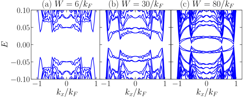
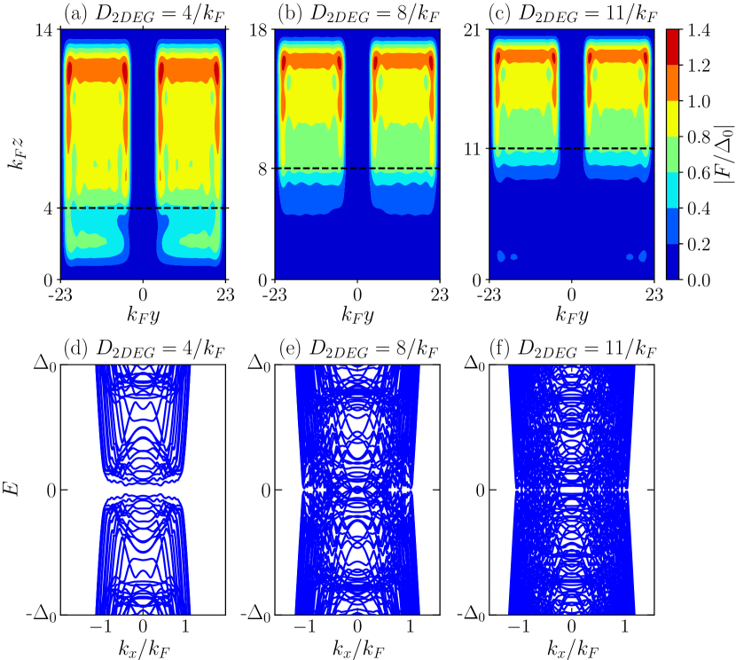
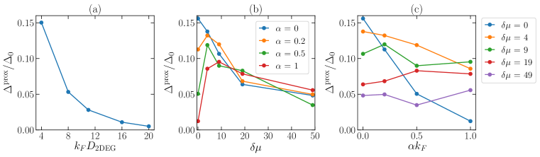
Figure 6 addresses the effect of varying the thickness of the 2DEG on the proximity gap, illustrating another effect associated with geometry. Shown here are plots of the pair amplitude (upper panel) and energy spectra (lower panel) of the Josephson junction. It can be seen from the plots that the pair amplitude and spectral gap decrease with increasing thickness of the 2DEG. There are contrary suggestions in the literature Lutchyn et al. (2011); Stanescu et al. (2011) that these thicker substrates could be favorable as they allow “multichannel participation”. As shown here, though, thicker junctions lead to smaller proximity gaps since they require that the superconducting correlations extend over a greater distance deeper into the 2DEG. We, thus, conclude that as Majorana zero modes are protected by large proximity-induced gaps, thinner 2DEGs are more favorable to be used as platforms for topological quantum computation.
Figure 7 presents a summary of how is affected by geometry and materials parameters. This figure shows how increasing (a) the thickness, (b) the chemical potential difference and (c) the SOC strength affect the proximity gap (at zero Zeeman field and zero phase difference). Clearly making both the thickness and the channel width larger has deleterious effects. However, as shown in Figs. 7(b) and 7(c), the effects of SOC are strongly connected to the magnitude of the chemical potential difference () 333Note that the realistic picture of chemical potential mismatch can be quite complicated as it involves band bending and charge screening at the NS interface (which are not taken into account in our model). Taking the band bending into account implies that the larger the chemical potential mismatch between the 2DEG and the superconductor, the larger Rashba SOC field (due to larger electrical field at the interface).. As shown in Fig. 7(b), when there is any finite SOC, there is a notable nonmonotonicity in plots of versus . The initial rise in with for a fixed is due to the matching of the band structure of the superconductor with the Rashba-derived band structure in the 2DEG. However, once the chemical potential difference is sufficiently large, as might be expected, increasing it further has a negative effect on the proximity gap due to the mismatch in the Fermi momenta between the superconductors and 2DEG, as illustrated in Fig. 3. There seems to be a “sweet spot” around which is substantially below the more realistic physical regime (where might approach or larger). Figure 7(c) shows that the effects of SOC on the proximity gap becomes weaker as increases, as discussed in Sec. V.1. Overall this figure should help guide materials parameters and geometries 444We note that our results are obtained using parabolic dispersions for the semiconductor and superconductor. In general, the semiconductor band structure is well approximated by a parabolic band dispersion since the chemical potential of a semiconductor is close to the band bottom. Our choice of the band structure for superconductor will not affect our results as the effect of the band structure of the superconductor is independent of the effect of the above three parameters (thickness, spin-orbit coupling, and chemical potential mismatch) on the proximity gap..
VI Symmetry class
It is useful to look at the underlying symmetries which dictate the nature of the topological phases. The above BdG Hamiltonian [Eq. (II.1)] for the planar Josephson junction commutes with the particle-hole symmetry operator where is the complex conjugation. For zero Zeeman field and a superconducting phase bias or , the Hamiltonian belongs to the symmetry class DIII in the tenfold classification Kitaev (2009); Ryu et al. (2010); Altland and Zirnbauer (1997) as it also commutes with the time-reversal symmetry operator (where ). Moreover, the system also has a mirror symmetry along the - plane with the mirror operator given by .
The and symmetries are broken when an in-plane Zeeman field is applied along the junction ( direction) or for a phase bias other than or . The Hamiltonian, however, remains invariant under an antiunitary “effective” time-reversal operator which is the product of the and operators, i.e., where . Thus the system has the BDI symmetry Pientka et al. (2017); Hell et al. (2017). Moreover, since the Hamiltonian possesses and symmetries, it also has a chiral symmetry, where the Hamiltonian anticommutes with the chirality operator . When the symmetry is broken, the symmetry class is reduced from class BDI to class D. In this case, an even number of Majorana zero modes at the same end of the junction couples to each other and splits into finite-energy mode leaving either zero or one Majorana mode at each end of the junction. This BDI symmetry can be broken by disorder Haim and Stern (2019), applying a transverse Zeeman field perpendicular to the junction (along the direction) Setiawan et al. (2019) or having left and right superconductors with different widths or pairing potentials Pientka et al. (2017); Hell et al. (2017); Setiawan et al. (2019).
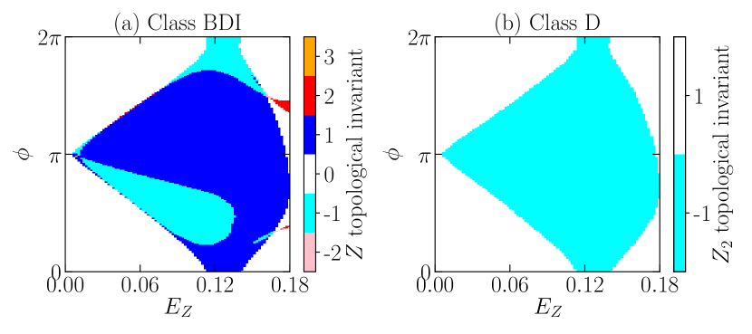
The symmetry class BDI is characterized by a topological invariant where denotes the number of Majorana zero modes at each end of the junctions. On the other hand, the symmetry class D is characterized by a topological invariant which denotes the parity of the invariant.
VII Topological phase diagram and transition
We obtain the phase diagram of the system by calculating the topological invariant following Ref. Tewari and Sau (2012). The numerical computation is considerably more complicated in the presence of our full treatment of proximitization. To do so, we first diagonalize the chiral operator with and in the upper-left and lower-right block, respectively. Since , in this basis where the is block diagonal, the BdG Hamiltonian is off diagonal, i.e.,
| (27a) | ||||
| (27b) | ||||
We can calculate the topological invariant () from the winding of the phase of the determinant of the off-diagonal part where . The topological invariant is given by
| (28) |
and the topological invariant (the parity of ) is given by
| (29) |
It is shown in Ref. Tewari and Sau (2012) that Eq. (29) is simply the Pfaffian invariant of 1D systems Kitaev (2001), i.e.,
| (30) |
Figures 8 and 9 present the phase diagrams of the planar Josephson junction obtained from the full proximity calculations. These phase diagrams emphasize the novel feature of the Josephson-junction architecture which enables the topological phase to be tuned either by changing the phase bias or the Zeeman field.
Figure 8 shows the class BDI and class D phase diagrams for the same junction. Each phase in the BDI phase diagram [Fig. 8(a)] is labeled by a different topological invariant () where denotes the number of Majorana zero modes located at each end of the junction. As can be seen from Fig. 8(a), the topological region occupies most of the phase diagram as it occurs in a wide range of parameters. The topological transition between each of the BDI phases is indicated by a gap closing at . The class D phase diagram [Fig. 8(b)], on the other hand, shows the parity of the topological invariant [Eq. (29)] where and correspond to the trivial and topological phases of class D, respectively. The topological transition between the and regions is reflected in a gap closing at Kitaev (2001) (see Sec. VII.1).
The bulk-boundary correspondence implies that the change in the topological index from to which is accompanied by a bulk gap closing at corresponds to the appearance of a Majorana zero mode at the end of a finite-length junction. Importantly, the edge states that appear in a finite-length junction of our model are Majorana zero modes and not Andreev bound states. Clearly, Andreev bound states do not involve a change of topological index (from trivial to topological) and are also not accompanied by bulk gap closings.
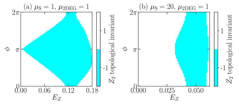
Figure 9 shows the effect of chemical potential mismatch () on the phase dependence of the class D phase diagram. For an ideal or “transparent” Josephson junction, the phase diagram has a diamond shape where the critical Zeeman field at which the topological phase transition happens is considerably smaller for than for [see Fig. 9(a)]. We observe that, with a larger value for , the phase diagram appears to be more stripelike as in Fig. 9(b). Here, the dependence of the phase diagram on the superconducting phase difference becomes weaker and the critical Zeeman field for shifts to a larger value.
We understand this stripelike phase diagram as deriving from an increasing mismatch between the chemical potential of the superconductor and the 2DEG. This, in turn, should be viewed as leading to an increase in the strength of the normal reflections in the 2DEG. Due to the proximity to the superconductor, the chemical potential of the 2DEG directly in contact with the superconductor will be renormalized by that of the superconductor. As a result, there is a difference between the effective chemical potential of the 2DEG directly below the superconductor with the effective chemical potential of the 2DEG in the junction. This effectively creates a potential barrier for the electrons which in turn increases the strength of normal reflections.
We conclude this section by noting that under ideal circumstances (i.e., for transparent junctions with small ), the critical Zeeman field needed to tune the system to topological phases can be greatly reduced for a phase bias . One can infer from Fig. 9(b), that when assumes a substantial (and physically reasonable) value, this gain in reduction of the critical Zeeman field (by tuning the phase to be near ) is mostly lost 555It can be noted that we use the same effective electron mass in the superconductor and 2DEG in addressing proximitization within this paper, and, thus, we may be overestimating the reduction in the phase dependence of the class D phase diagram and the proximity-induced gap due to the chemical potential mismatch .. We note that similar to the effect of , decreasing the width of the superconducting leads also makes the phase diagram becomes less dependent on the phase bias due to the enhancement of multiple normal reflections at the interface between the superconductors and the vacuum Setiawan et al. (2019).
VII.1 Energy dispersion across the topological phase transition
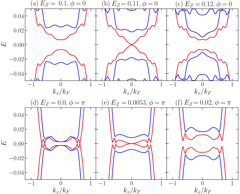
The topological phase transition of class D is associated with a gap closing at Kitaev (2001). As can be seen from the phase diagram [Fig. 9(a)], for a transparent junction the critical Zeeman field at which the transition happens is much smaller when the superconducting phase difference is near . As a complement to this phase diagram, we address the energy spectrum of the system as a function of across the phase transition.
Figure 10 shows the evolution of the energy spectrum of a planar Josephson junction as the Zeeman field is tuned across the topological phase transition for two different values of superconducting phase differences: (upper panel) and (lower panel). At a particular value of critical field , the gap at closes [panels (b) and (e)] which reflects the transition between trivial and topological phases. The critical Zeeman field is reduced as .
We summarize this section by noting that despite the more indirect form of proximitization associated with this Josephson-junction architecture, as compared with the nanowires of Fig. 1(b), we have presented strong evidence that proximitized topological phases exist. This topological superconductivity occurs even when there are no direct attractive interactions in the 2DEG channel. Nevertheless, in this Josephson-junction configuration the proximity coupling guarantees that there is a finite pair amplitude within the channel.
VIII Proximity-induced FFLO phase
An exotic superconducting state, characterized by nonzero center-of-mass momentum of Cooper pairs and spatially varying order parameter, may occur for certain materials in the presence of both in-plane magnetic field and superconductivity. Interestingly, the planar junctions discussed here are associated with this exotic form of superconductivity, referred to as the Fulde-Ferrell-Larkin-Ovchinikov (FFLO) phase Fulde and Ferrell (1964); Larkin and Ovchinnikov (1964). Indeed, it is hard to find examples where this elusive phase, deriving from magnetic field effects, has been observed Chen et al. (2018) which do not originate from proximity coupling. Experiments based on this Josephson-junction architecture Hart et al. (2017) report that the FFLO phase appears to be confined within the 1D channel of the junction. One might have expected it to be present in some form throughout the 2DEG since magnetic fields and proximity coupling are present outside the channel as well. Due to the close proximity to the parent superconductor the induced gap there, however, is stronger and is not energetically favorable to oscillate in response to an applied in-plane Zeeman field. The channel in the junction, on the other hand, is well away from the host superconductors and thus has greatly weakened pair amplitude with superconducting phases which are freer to oscillate.
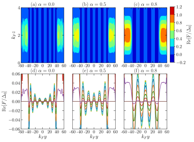
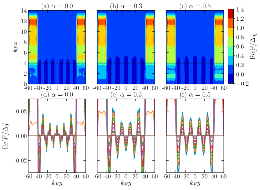
The upper panel of Fig. 11 presents a contour plot of the pair amplitude throughout the junction. We point out that the junctions considered here are very wide. They correspond to the widest case shown in Fig. 5(c) where the proximity gap is extremely small. This weak proximity gap is not favorable to topological superconductivity. This figure should make it clear, however, that even though the channel is wide, the existence of a FFLO phase demonstrates that the channel should be viewed as a proximitized superconductor, rather than as a strictly “normal” region. Shown in the upper panel of Fig. 11 are the pair amplitudes for three different values of SOC strength. The lower panel of Fig. 11 presents linecuts of this pair amplitude along the direction at different values of . As can be seen from the figure, the oscillations of the pair amplitude are confined to the 2DEG channel; this oscillation can manifest as the oscillation in the critical current as a function of an in-plane Zeeman field as observed in recent experiments Hart et al. (2017). The frequency of these oscillations scales appropriately with both the applied in-plane Zeeman field and the SOC strength.
In Appendix A we show that the FFLO state is also present for the case of 1D Rashba SOC. There we also illustrate how the same behavior can be found in the effective models where the superconducting hosts have been “integrated out”.
In general, the amplitude of the FFLO oscillation decreases with increasing temperature Heikkinen et al. (2013) as temperature weakens FFLO pairing. Since the typical experimental temperature (from 0.5 K down to 31 mK Ren et al. (2019)) is well below the superconducting critical temperature ( of an Al film is 1.2-1.6 K Ren et al. (2019)), the FFLO order should be experimentally observable, as reported in recent work on Al-proximitized HgTe quantum wells Hart et al. (2017). We note that since the proximitization strength decreases with increasing junction width, the FFLO oscillation amplitude decays towards the middle of the junction (away from the superconductor). This implies that the FFLO phase of a narrower junction is associated with a larger proximitized gap in the middle of the junction.
The presence of nonmagnetic disorder will decrease the amplitude and period of the FFLO oscillations. This is because the associated scattering involves an averaging of the effective magnitude of the magnetic field over all directions (from a minimum value of 0 to a maximum value of ), yielding a shorter oscillation period Demler et al. (1997). Magnetic disorder, on the other hand, leads to a decrease in the characteristic decay length and an increase in the period of oscillations Buzdin (2005, 1985).
IX Conclusions
While heterostructures that involve proximitization appear to be important for achieving topological superconductivity, the major components required to achieve this phase are in many ways inimical to the proximitization process. These involve Zeeman fields, spin-orbit coupling which can lead to band-structure mismatches and substantial chemical potential discontinuities between the parent superconductors and the proximitized (often semiconducting) medium. Nevertheless, experiments Ren et al. (2019); Fornieri et al. (2019) seem to be demonstrating success. Although theoretically we might expect this proximitization to be a rather delicate and fragile process, nevertheless, we are able to show that there are clear indications of well-established topological superconductivity. The figures throughout this paper illustrate this situation. We stress that in our Josephson-junction configuration the proximity is more remote compared to that in the conventional nanowire configuration of Fig. 1(b).
Because we have focused on the proximitization process itself, in this paper we were able to consider how to maximize the proximity gap both by varying geometry as well as materials parameters. This particular parameter is understood to be computed in the absence of Zeeman field or phase difference. It nevertheless sets the scale for the energy gap in the topological phase, , and thereby for the stability of Majorana zero modes.
Figure 7 presents a summary of our major findings. One should aim for junctions with very thin 2DEG regions and narrow channels between the host superconductors. Additionally, there is a delicate competition between the chemical potential differences of the 2DEG and the superconductors (), and the Rashba SOC strength. While a larger serves to compensate for deleterious effects of SOC, it cannot be too big. Indeed, Fig. 9(b) shows that one major knob of the Josephson junction architecture (which is the ability to tune the phase difference to and thereby require very small Zeeman fields to access topological phases) is undermined if is too large.
Finally, by plotting the pair amplitude itself, we have provided in this paper very direct evidence for the elusive FFLO phase. It is not necessarily to be associated with topological physics, but it has some of the same requirements. We show how the presence of Zeeman fields together with SOC and (remote) proximity effect stabilize this state which exists entirely inside the 2DEG channel, much as in recent experiments Hart et al. (2017).
Acknowledgements.
We thank Erez Berg for helpful conversations. This work was supported by NSF-DMR-MRSEC 1420709. C.-T.W. is supported by the MOST Grant No. 106-2112-M-009-001-MY2. We acknowledge the University of Chicago Research Computing Center for support of this work.References
- Lutchyn et al. (2010) Roman M. Lutchyn, Jay D. Sau, and S. Das Sarma, “Majorana fermions and a topological phase transition in semiconductor-superconductor heterostructures,” Phys. Rev. Lett. 105, 077001 (2010).
- Oreg et al. (2010) Yuval Oreg, Gil Refael, and Felix von Oppen, “Helical liquids and majorana bound states in quantum wires,” Phys. Rev. Lett. 105, 177002 (2010).
- Alicea (2012) Jason Alicea, “New directions in the pursuit of majorana fermions in solid state systems,” Reports on progress in physics 75, 076501 (2012).
- Leijnse and Flensberg (2012) Martin Leijnse and Karsten Flensberg, “Introduction to topological superconductivity and majorana fermions,” Semiconductor Science and Technology 27, 124003 (2012).
- Stanescu and Tewari (2013) Tudor D Stanescu and Sumanta Tewari, “Majorana fermions in semiconductor nanowires: fundamentals, modeling, and experiment,” Journal of Physics: Condensed Matter 25, 233201 (2013).
- Beenakker (2013) C W J Beenakker, “Search for majorana fermions in superconductors,” Annu. Rev. Con. Mat. Phys. 4, 113–136 (2013).
- Elliott and Franz (2015) Steven R. Elliott and Marcel Franz, “Colloquium: Majorana fermions in nuclear, particle, and solid-state physics,” Rev. Mod. Phys. 87, 137–163 (2015).
- Sarma et al. (2015) Sankar Das Sarma, Michael Freedman, and Chetan Nayak, “Majorana zero modes and topological quantum computation,” npj Quantum Information 1, 15001 (2015).
- Aguado (2018) Ramón Aguado, “Majorana quasiparticles in condensed matter,” Riv. Nuovo Cimento 40, 523–593 (2018).
- Lutchyn et al. (2018) RM Lutchyn, EPAM Bakkers, LP Kouwenhoven, P Krogstrup, CM Marcus, and Y Oreg, “Majorana zero modes in superconductor–semiconductor heterostructures,” Nature Reviews Materials 3, 52 (2018).
- Pientka et al. (2017) Falko Pientka, Anna Keselman, Erez Berg, Amir Yacoby, Ady Stern, and Bertrand I. Halperin, “Topological superconductivity in a planar josephson junction,” Phys. Rev. X 7, 021032 (2017).
- Hell et al. (2017) Michael Hell, Martin Leijnse, and Karsten Flensberg, “Two-dimensional platform for networks of majorana bound states,” Phys. Rev. Lett. 118, 107701 (2017).
- Sengupta et al. (2001) K. Sengupta, Igor Žutić, Hyok-Jon Kwon, Victor M. Yakovenko, and S. Das Sarma, “Midgap edge states and pairing symmetry of quasi-one-dimensional organic superconductors,” Phys. Rev. B 63, 144531 (2001).
- Law et al. (2009) K. T. Law, Patrick A. Lee, and T. K. Ng, “Majorana fermion induced resonant andreev reflection,” Phys. Rev. Lett. 103, 237001 (2009).
- Flensberg (2010) Karsten Flensberg, “Tunneling characteristics of a chain of majorana bound states,” Phys. Rev. B 82, 180516 (2010).
- Prada et al. (2012) Elsa Prada, Pablo San-Jose, and Ramón Aguado, “Transport spectroscopy of nanowire junctions with majorana fermions,” Phys. Rev. B 86, 180503 (2012).
- Mourik et al. (2012) V. Mourik, K. Zuo, S. M. Frolov, S. R. Plissard, E. P. A. M. Bakkers, and L. P. Kouwenhoven, “Signatures of majorana fermions in hybrid superconductor-semiconductor nanowire devices,” Science 336, 1003–1007 (2012).
- Rokhinson et al. (2012) Leonid P Rokhinson, Xinyu Liu, and Jacek K Furdyna, “The fractional ac josephson effect in a semiconductor-superconductor nanowire as a signature of majorana particles,” Nat. Phys. 8, 795–799 (2012).
- Deng et al. (2012) M. T. Deng, C. L. Yu, G. Y. Huang, M. Larsson, P. Caroff, and H. Q. Xu, “Anomalous zero-bias conductance peak in a nb–insb nanowire–nb hybrid device,” Nano Lett. 12, 6414–6419 (2012).
- Das et al. (2012) Anindya Das, Yuval Ronen, Yonatan Most, Yuval Oreg, Moty Heiblum, and Hadas Shtrikman, “Zero-bias peaks and splitting in an al-inas nanowire topological superconductor as a signature of majorana fermions,” Nat. Phys. 8, 887–895 (2012).
- Churchill et al. (2013) H. O. H. Churchill, V. Fatemi, K. Grove-Rasmussen, M. T. Deng, P. Caroff, H. Q. Xu, and C. M. Marcus, “Superconductor-nanowire devices from tunneling to the multichannel regime: Zero-bias oscillations and magnetoconductance crossover,” Phys. Rev. B 87, 241401 (2013).
- Finck et al. (2013) A. D. K. Finck, D. J. Van Harlingen, P. K. Mohseni, K. Jung, and X. Li, “Anomalous modulation of a zero-bias peak in a hybrid nanowire-superconductor device,” Phys. Rev. Lett. 110, 126406 (2013).
- Albrecht et al. (2016) Sven Marian Albrecht, AP Higginbotham, Morten Madsen, Ferdinand Kuemmeth, Thomas Sand Jespersen, Jesper Nygård, Peter Krogstrup, and CM Marcus, “Exponential protection of zero modes in majorana islands,” Nature 531, 206 (2016).
- Gül et al. (2018) Önder Gül, Hao Zhang, Jouri DS Bommer, Michiel WA de Moor, Diana Car, Sébastien R Plissard, Erik PAM Bakkers, Attila Geresdi, Kenji Watanabe, Takashi Taniguchi, et al., “Ballistic majorana nanowire devices,” Nature nanotechnology 13, 192 (2018).
- Chen et al. (2017) Jun Chen, Peng Yu, John Stenger, Moïra Hocevar, Diana Car, Sébastien R Plissard, Erik PAM Bakkers, Tudor D Stanescu, and Sergey M Frolov, “Experimental phase diagram of zero-bias conductance peaks in superconductor/semiconductor nanowire devices,” Science advances 3, e1701476 (2017).
- Deng et al. (2016) MT Deng, S Vaitiekėnas, Esben Bork Hansen, Jeroen Danon, M Leijnse, Karsten Flensberg, Jesper Nygård, P Krogstrup, and Charles M Marcus, “Majorana bound state in a coupled quantum-dot hybrid-nanowire system,” Science 354, 1557–1562 (2016).
- Suominen et al. (2017) H. J. Suominen, M. Kjaergaard, A. R. Hamilton, J. Shabani, C. J. Palmstrøm, C. M. Marcus, and F. Nichele, “Zero-energy modes from coalescing andreev states in a two-dimensional semiconductor-superconductor hybrid platform,” Phys. Rev. Lett. 119, 176805 (2017).
- Nichele et al. (2017) Fabrizio Nichele, Asbjørn C. C. Drachmann, Alexander M. Whiticar, Eoin C. T. O’Farrell, Henri J. Suominen, Antonio Fornieri, Tian Wang, Geoffrey C. Gardner, Candice Thomas, Anthony T. Hatke, Peter Krogstrup, Michael J. Manfra, Karsten Flensberg, and Charles M. Marcus, “Scaling of majorana zero-bias conductance peaks,” Phys. Rev. Lett. 119, 136803 (2017).
- Zhang et al. (2018) Hao Zhang, Chun-Xiao Liu, Sasa Gazibegovic, Di Xu, John A Logan, Guanzhong Wang, Nick Van Loo, Jouri DS Bommer, Michiel WA De Moor, Diana Car, et al., “Quantized majorana conductance,” Nature 556, 74 (2018).
- Zhang et al. (2017) Hao Zhang, Önder Gül, Sonia Conesa-Boj, Michał P Nowak, Michael Wimmer, Kun Zuo, Vincent Mourik, Folkert K De Vries, Jasper Van Veen, Michiel WA De Moor, et al., “Ballistic superconductivity in semiconductor nanowires,” Nature communications 8, 16025 (2017).
- Sestoft et al. (2018) Joachim E. Sestoft, Thomas Kanne, Aske Nørskov Gejl, Merlin von Soosten, Jeremy S. Yodh, Daniel Sherman, Brian Tarasinski, Michael Wimmer, Erik Johnson, Mingtang Deng, Jesper Nygård, Thomas Sand Jespersen, Charles M. Marcus, and Peter Krogstrup, “Engineering hybrid epitaxial inassb/al nanowires for stronger topological protection,” Phys. Rev. Materials 2, 044202 (2018).
- Deng et al. (2018) M.-T. Deng, S. Vaitiekėnas, E. Prada, P. San-Jose, J. Nygård, P. Krogstrup, R. Aguado, and C. M. Marcus, “Nonlocality of majorana modes in hybrid nanowires,” Phys. Rev. B 98, 085125 (2018).
- Laroche et al. (2019) Dominique Laroche, Daniël Bouman, David J van Woerkom, Alex Proutski, Chaitanya Murthy, Dmitry I Pikulin, Chetan Nayak, Ruben JJ van Gulik, Jesper Nygård, Peter Krogstrup, et al., “Observation of the 4-periodic josephson effect in indium arsenide nanowires,” Nature Communications 10, 245 (2019).
- van Veen et al. (2018) Jasper van Veen, Alex Proutski, Torsten Karzig, Dmitry I. Pikulin, Roman M. Lutchyn, Jesper Nygård, Peter Krogstrup, Attila Geresdi, Leo P. Kouwenhoven, and John D. Watson, “Magnetic-field-dependent quasiparticle dynamics of nanowire single-cooper-pair transistors,” Phys. Rev. B 98, 174502 (2018).
- de Moor et al. (2018) Michiel WA de Moor, Jouri DS Bommer, Di Xu, Georg W Winkler, Andrey E Antipov, Arno Bargerbos, Guanzhong Wang, Nick van Loo, Roy LM Veld, Sasa Gazibegovic, et al., “Electric field tunable superconductor-semiconductor coupling in majorana nanowires,” New Journal of Physics 20, 103049 (2018).
- Grivnin et al. (2018) Anna Grivnin, Ella Bor, Moty Heiblum, Yuval Oreg, and Hadas Shtrikman, “Concomitant opening of a topological bulk-gap with an emerging majorana edge-state,” arXiv:1807.06632 (2018).
- Vaitiekėnas et al. (2018) S Vaitiekėnas, M-T Deng, P Krogstrup, and CM Marcus, “Flux-induced majorana modes in full-shell nanowires,” arXiv:1809.05513 (2018).
- Ren et al. (2019) Hechen Ren, Falko Pientka, Sean Hart, Andrew Pierce, Michael Kosowsky, Lukas Lunczer, Raimund Schlereth, Benedikt Scharf, Ewelina M. Hankiewicz, Laurens W. Molenkamp, Bertrand I. Halperin, and Amir Yacoby, “Topological superconductivity in a phase-controlled josephson junction,” Nature 569, 93 (2019).
- Fornieri et al. (2019) Antonio Fornieri, Alexander M. Whiticar, F. Setiawan, Elías Portolés Marín, Asbjorn C. C. Drachmann, Anna Keselman, Sergei Gronin, Candice Thomas, Tian Wang, Ray Kallaher, Geoffrey C. Gardner, Erez Berg, Michael J. Manfra, Ady Stern, Charles M. Marcus, and Fabrizio Nichele, “Evidence of topological superconductivity in planar josephson junctions,” Nature 569, 89 (2019).
- McMillan (1968a) W. L. McMillan, “Tunneling model of the superconducting proximity effect,” Phys. Rev. 175, 537–542 (1968a).
- McMillan (1968b) W. L. McMillan, “Theory of superconductor—normal-metal interfaces,” Phys. Rev. 175, 559–568 (1968b).
- Sau et al. (2010) Jay D. Sau, Roman M. Lutchyn, Sumanta Tewari, and S. Das Sarma, “Robustness of majorana fermions in proximity-induced superconductors,” Phys. Rev. B 82, 094522 (2010).
- Stanescu et al. (2010) Tudor D. Stanescu, Jay D. Sau, Roman M. Lutchyn, and S. Das Sarma, “Proximity effect at the superconductor–topological insulator interface,” Phys. Rev. B 81, 241310 (2010).
- Potter and Lee (2011) Andrew C. Potter and Patrick A. Lee, “Engineering a superconductor: Comparison of topological insulator and rashba spin-orbit-coupled materials,” Phys. Rev. B 83, 184520 (2011).
- Note (1) Although not all of the results presented in this paper are fully self-consistent, we have checked in a few cases that increasing the number of iterations only very slightly modifies our results.
- Fulde and Ferrell (1964) Peter Fulde and Richard A. Ferrell, “Superconductivity in a strong spin-exchange field,” Phys. Rev. 135, A550 (1964).
- Larkin and Ovchinnikov (1964) AI Larkin and Yu N Ovchinnikov, “Nonuniform state of superconductors,” Zh. Eksp. Teor. Fiz. 47, 1136 (1964).
- Hart et al. (2017) Sean Hart, Hechen Ren, Michael Kosowsky, Gilad Ben-Shach, Philipp Leubner, Christoph Brüne, Hartmut Buhmann, Laurens W Molenkamp, Bertrand I Halperin, and Amir Yacoby, “Controlled finite momentum pairing and spatially varying order parameter in proximitized hgte quantum wells,” Nature Physics 13, 87 (2017).
- Chen et al. (2018) Angela Q Chen, Moon Jip Park, Stephen T Gill, Yiran Xiao, Dalmau Reig-i Plessis, Gregory J MacDougall, Matthew J Gilbert, and Nadya Mason, “Finite momentum cooper pairing in three-dimensional topological insulator josephson junctions,” Nature communications 9, 3478 (2018).
- Nadj-Perge et al. (2014) Stevan Nadj-Perge, Ilya K Drozdov, Jian Li, Hua Chen, Sangjun Jeon, Jungpil Seo, Allan H MacDonald, B Andrei Bernevig, and Ali Yazdani, “Observation of majorana fermions in ferromagnetic atomic chains on a superconductor,” Science 346, 602 (2014).
- Klinovaja et al. (2013) Jelena Klinovaja, Peter Stano, Ali Yazdani, and Daniel Loss, “Topological superconductivity and majorana fermions in rkky systems,” Phys. Rev. Lett. 111, 186805 (2013).
- Nadj-Perge et al. (2013) S. Nadj-Perge, I. K. Drozdov, B. A. Bernevig, and Ali Yazdani, “Proposal for realizing majorana fermions in chains of magnetic atoms on a superconductor,” Phys. Rev. B 88, 020407 (2013).
- Li et al. (2014) Jian Li, Hua Chen, Ilya K. Drozdov, A. Yazdani, B. Andrei Bernevig, and A. H. MacDonald, “Topological superconductivity induced by ferromagnetic metal chains,” Phys. Rev. B 90, 235433 (2014).
- Li et al. (2016) J Li, T Neupert, Z Wang, A H MacDonald, Y Yazdani, and A Bernevig, “Two-dimensional chiral topological superconductivity in shiba lattices,” Nature Communications 7, 12297 (2016).
- Brydon et al. (2015) P. M. R. Brydon, S. Das Sarma, Hoi-Yin Hui, and Jay D. Sau, “Topological yu-shiba-rusinov chain from spin-orbit coupling,” Phys. Rev. B 91, 064505 (2015).
- Hui et al. (2015) Hoi-Yin Hui, PMR Brydon, Jay D Sau, S Tewari, and S Das Sarma, “Majorana fermions in ferromagnetic chains on the surface of bulk spin-orbit coupled s-wave superconductors,” Scientific reports 5, 8880 (2015).
- Fu and Kane (2008) Liang Fu and C. L. Kane, “Superconducting proximity effect and majorana fermions at the surface of a topological insulator,” Phys. Rev. Lett. 100, 096407 (2008).
- Xu et al. (2015) Jin-Peng Xu, Mei-Xiao Wang, Zhi Long Liu, Jian-Feng Ge, Xiaojun Yang, Canhua Liu, Zhu An Xu, Dandan Guan, Chun Lei Gao, Dong Qian, Ying Liu, Qiang-Hua Wang, Fu-Chun Zhang, Qi-Kun Xue, and Jin-Feng Jia, “Experimental detection of a majorana mode in the core of a magnetic vortex inside a topological insulator-superconductor heterostructure,” Phys. Rev. Lett. 114, 017001 (2015).
- Sun et al. (2016) Hao-Hua Sun, Kai-Wen Zhang, Lun-Hui Hu, Chuang Li, Guan-Yong Wang, Hai-Yang Ma, Zhu-An Xu, Chun-Lei Gao, Dan-Dan Guan, Yao-Yi Li, Canhua Liu, Dong Qian, Yi Zhou, Liang Fu, Shao-Chun Li, Fu-Chun Zhang, and Jin-Feng Jia, “Majorana zero mode detected with spin selective andreev reflection in the vortex of a topological superconductor,” Phys. Rev. Lett. 116, 257003 (2016).
- Fu and Berg (2010) Liang Fu and Erez Berg, “Odd-parity topological superconductors: Theory and application to ,” Phys. Rev. Lett. 105, 097001 (2010).
- Sasaki et al. (2011) Satoshi Sasaki, M. Kriener, Kouji Segawa, Keiji Yada, Yukio Tanaka, Masatoshi Sato, and Yoichi Ando, “Topological superconductivity in ,” Phys. Rev. Lett. 107, 217001 (2011).
- Peng et al. (2013) Haibing Peng, Debtanu De, Bing Lv, Fengyan Wei, and Ching-Wu Chu, “Absence of zero-energy surface bound states in cuxbi2se3 studied via andreev reflection spectroscopy,” Phys. Rev. B 88, 024515 (2013).
- Chiu et al. (2016) Ching-Kai Chiu, William S. Cole, and S. Das Sarma, “Induced spectral gap and pairing correlations from superconducting proximity effect,” Phys. Rev. B 94, 125304 (2016).
- Stanescu and Das Sarma (2013) Tudor D. Stanescu and S. Das Sarma, “Superconducting proximity effect in semiconductor nanowires,” Phys. Rev. B 87, 180504 (2013).
- Winkler (2003) Roland Winkler, “Spin-orbit coupling effects in two-dimensional electron and hole systems,” Springer Tracts in Modern Physics 191, 1–8 (2003).
- Mikkelsen et al. (2018) August E. G. Mikkelsen, Panagiotis Kotetes, Peter Krogstrup, and Karsten Flensberg, “Hybridization at superconductor-semiconductor interfaces,” Phys. Rev. X 8, 031040 (2018).
- Antipov et al. (2018) Andrey E. Antipov, Arno Bargerbos, Georg W. Winkler, Bela Bauer, Enrico Rossi, and Roman M. Lutchyn, “Effects of gate-induced electric fields on semiconductor majorana nanowires,” Phys. Rev. X 8, 031041 (2018).
- Sticlet et al. (2017) Doru Sticlet, Bas Nijholt, and Anton Akhmerov, “Robustness of majorana bound states in the short-junction limit,” Phys. Rev. B 95, 115421 (2017).
- Stanescu and Das Sarma (2017) Tudor D. Stanescu and Sankar Das Sarma, “Proximity-induced low-energy renormalization in hybrid semiconductor-superconductor majorana structures,” Phys. Rev. B 96, 014510 (2017).
- Halterman and Valls (2001) Klaus Halterman and Oriol T. Valls, “Proximity effects at ferromagnet-superconductor interfaces,” Phys. Rev. B 65, 014509 (2001).
- Wu et al. (2012) Chien-Te Wu, Oriol T. Valls, and Klaus Halterman, “Proximity effects in conical-ferromagnet/superconductor bilayers,” Phys. Rev. B 86, 184517 (2012).
- Wu et al. (2017) Chien-Te Wu, Brandon M. Anderson, Wei-Han Hsiao, and K. Levin, “Majorana zero modes in spintronics devices,” Phys. Rev. B 95, 014519 (2017).
- Wu et al. (2018) Chien-Te Wu, F. Setiawan, Brandon M. Anderson, Wei-Han Hsiao, and K. Levin, “Quantum phase transitions in proximitized josephson junctions,” Phys. Rev. B 98, 064504 (2018).
- Stanescu et al. (2011) Tudor D. Stanescu, Roman M. Lutchyn, and S. Das Sarma, “Majorana fermions in semiconductor nanowires,” Phys. Rev. B 84, 144522 (2011).
- Nambu (1960) Yoichiro Nambu, “Quasi-particles and gauge invariance in the theory of superconductivity,” Phys. Rev. 117, 648–663 (1960).
- Eliashberg (1960) GM Eliashberg, “Interactions between electrons and lattice vibrations in a superconductor,” Sov. Phys. JETP 11, 696–702 (1960).
- Schrieffer (1964) J Robert Schrieffer, Theory of superconductivity (W. A. Benjamin, New York, 1964).
- Pannetier and Courtois (2000) B Pannetier and H Courtois, “Andreev reflection and proximity effect,” Journal of low temperature physics 118, 599–615 (2000).
- Klapwijk (2004) TM Klapwijk, “Proximity effect from an andreev perspective,” Journal of superconductivity 17, 593–611 (2004).
- Note (2) The transparency of the interface between the superconductor and 2DEG is determined by the matching of the Fermi velocity between the two materials. While the difference between the Fermi energy of the superconductor and semiconductor can be of several orders of magnitude, the Fermi velocity between the two has a smaller mismatch in magnitude because of a smaller electron effective mass of the semiconductor, which is not accommodated here. We note that the transparency is also affected by microscopic parameters such as the tunnel coupling strength and charge accumulation at the 2DEG-SC interface which are not accounted for in our model.
- Lutchyn et al. (2011) Roman M. Lutchyn, Tudor D. Stanescu, and S. Das Sarma, “Search for majorana fermions in multiband semiconducting nanowires,” Phys. Rev. Lett. 106, 127001 (2011).
- Note (3) Note that the realistic picture of chemical potential mismatch can be quite complicated as it involves band bending and charge screening at the NS interface (which are not taken into account in our model). Taking the band bending into account implies that the larger the chemical potential mismatch between the 2DEG and the superconductor, the larger Rashba SOC field (due to larger electrical field at the interface).
- Note (4) We note that our results are obtained using parabolic dispersions for the semiconductor and superconductor. In general, the semiconductor band structure is well approximated by a parabolic band dispersion since the chemical potential of a semiconductor is close to the band bottom. Our choice of the band structure for superconductor will not affect our results as the effect of the band structure of the superconductor is independent of the effect of the above three parameters (thickness, spin-orbit coupling, and chemical potential mismatch) on the proximity gap.
- Kitaev (2009) Alexei Kitaev, “Periodic table for topological insulators and superconductors,” in AIP Conference Proceedings, Vol. 1134 (AIP, 2009) pp. 22–30.
- Ryu et al. (2010) Shinsei Ryu, Andreas P Schnyder, Akira Furusaki, and Andreas WW Ludwig, “Topological insulators and superconductors: tenfold way and dimensional hierarchy,” New Journal of Physics 12, 065010 (2010).
- Altland and Zirnbauer (1997) Alexander Altland and Martin R. Zirnbauer, “Nonstandard symmetry classes in mesoscopic normal-superconducting hybrid structures,” Phys. Rev. B 55, 1142–1161 (1997).
- Haim and Stern (2019) Arbel Haim and Ady Stern, “Benefits of weak disorder in one-dimensional topological superconductors,” Phys. Rev. Lett. 122, 126801 (2019).
- Setiawan et al. (2019) F. Setiawan, Ady Stern, and Erez Berg, “Topological superconductivity in planar josephson junctions – narrowing down to the nanowire limit,” arXiv:1902.11300 (2019).
- Tewari and Sau (2012) Sumanta Tewari and Jay D. Sau, “Topological invariants for spin-orbit coupled superconductor nanowires,” Phys. Rev. Lett. 109, 150408 (2012).
- Kitaev (2001) A Yu Kitaev, “Unpaired majorana fermions in quantum wires,” Physics-Uspekhi 44, 131 (2001).
- Note (5) It can be noted that we use the same effective electron mass in the superconductor and 2DEG in addressing proximitization within this paper, and, thus, we may be overestimating the reduction in the phase dependence of the class D phase diagram and the proximity-induced gap due to the chemical potential mismatch .
- Heikkinen et al. (2013) Miikka O. J. Heikkinen, Dong-Hee Kim, and Päivi Törmä, “Finite-temperature stability and dimensional crossover of exotic superfluidity in lattices,” Phys. Rev. B 87, 224513 (2013).
- Demler et al. (1997) E. A. Demler, G. B. Arnold, and M. R. Beasley, “Superconducting proximity effects in magnetic metals,” Phys. Rev. B 55, 15174–15182 (1997).
- Buzdin (2005) A. I. Buzdin, “Proximity effects in superconductor-ferromagnet heterostructures,” Rev. Mod. Phys. 77, 935–976 (2005).
- Buzdin (1985) A. I. Buzdin, “Surface superconductivity in ferromagnets,” Pis’ma Zh. Eksp. Teor. Fiz. 42, 283 (1985).
- Zheng et al. (2013) Zhen Zheng, Ming Gong, Xubo Zou, Chuanwei Zhang, and Guangcan Guo, “Route to observable fulde-ferrell-larkin-ovchinnikov phases in three-dimensional spin-orbit-coupled degenerate fermi gases,” Phys. Rev. A 87, 031602 (2013).
- Zheng et al. (2014) Zhen Zheng, Ming Gong, Yichao Zhang, Xubo Zou, Chuanwei Zhang, and Guangcan Guo, “Fflo superfluids in 2d spin-orbit coupled fermi gases,” Scientific reports 4, 6535 (2014).
- Wang et al. (2014) Da Wang, Zhoushen Huang, and Congjun Wu, “Fate and remnants of majorana zero modes in a quantum wire array,” Phys. Rev. B 89, 174510 (2014).
Appendix A FFLO phases
We begin by studying the mechanism for the formation of the FFLO phases. In the absence of SOC, the Fermi surfaces of up and down spins always form concentric circles as shown in Fig. A.1(a). For zero Zeeman fields, the superconducting pairing occurs between electrons carrying opposite spin with opposite momentum ( and ) on the Fermi surface where the Cooper pair has a zero center of mass momentum. If an in-plane magnetic field is applied to a system with no SOC, the Zeeman field enlarges and shrinks the Fermi surfaces radially in momentum by for the up and down spins, respectively, while keeping the two Fermi surfaces concentric. The pairing now occurs between the up- and down-spin electrons with different Fermi momenta, i.e., and where , so that the Cooper pairs have a net center of mass momentum of . When the applied in-plane Zeeman field is sufficiently strong, spatial symmetry needs to be broken in order to lower the ground state energy which results in the FFLO state. However, because of the Pauli depairing, this FFLO state only survives in a narrow parameter regime. This depairing effect in strong Zeeman fields can be mitigated by using the SOC, which allows both singlet and triplet pairings, since the triplet pairing is not sensitive to the depairing effect.
In the presence of Rashba SOC, the Hamiltonian of a 2DEG without a Zeeman field [Eq. (II.1)] is invariant when the spin and momentum are rotated simultaneously in the - plane, i.e.,
| (A.1) |
where
| (A.2) |
is the rotation operator in the - plane.
Note that the Hamiltonian still respects this rotational symmetry even in the presence of an out-of-plane Zeeman field (along the direction). However, the application of an in-plane Zeeman field along the junction, i.e., along the direction, breaks this rotational symmetry. The energy spectrum of the electron in the presence of the in-plane Zeeman field is given by
| (A.3) |
which breaks the rotational symmetry.
In the limit where , the two Fermi surfaces are shifted in the direction perpendicular to the Zeeman field direction (along ) by as shown in Fig. A.1(b). The pairing in this case occurs between up and down spins belonging to the same Fermi surface resulting also in Cooper pairs having a net momentum of . Thus the wave function of the Cooper pair can be written as , where and are the singlet and triplet pairing wave functions, respectively. So, the presence of SOC stabilizes the FFLO phase as the SOC lifts the spin degeneracy and shifts the Fermi surface in such a way that the resulting Cooper pair has a finite center of momentum Zheng et al. (2013, 2014).
In the main text we have shown how the FFLO phase appears in a proximitized junction in the presence of an in-plane Zeeman field and a conventional (2D) Rashba SOC. In this appendix we show that our findings are quite robust, appearing also for a 1D Rashba SOC as well as in the effective model. We self-consistently solve the BdG equations to obtain the pair amplitude [as given by Eq. (II.1) of the main text]:
| (A.4) |
Figure A.2 shows the pair amplitude for a 2DEG with a 1D Rashba spin-orbit-coupling . The pair amplitudes are calculated for different SOC strengths. As for the case of 2D Rashba spin-orbit-coupled electron gas, here we also find an oscillation of the pair amplitude within the junction channel and with the oscillation length scale given by which increases with increasing Zeeman field and decreases with increasing (as increases with increasing ). This is indicative of the FFLO phases formed in the presence of an applied in-plane magnetic field along the junction. We note that the Hamiltonian of a 2DEG with a 1D Rashba SOC can be mapped by a gauge transformation into the Hamiltonian of a conical Holmium magnet (Ref. Wu et al. (2018)) or coupled nanowires (Ref. Wang et al. (2014)) which are also platforms for topological superconductors.
Finally, Fig. A.3 shows the pair amplitude for the effective model [Eq. (IV.1)] of a planar Josephson junction with a 2D Rashba SOC. As shown in the figure, in the presence of an in-plane magnetic field, the pair amplitude oscillates inside the junction channel with an oscillation length which decreases with increasing SOC strength. Again, the oscillation is consistent with the formation of an FFLO phase in the presence of an in-plane magnetic field.