11email: duerrschnabel,hanika,stumme@cs.uni-kassel.de
DimDraw – A novel tool for drawing concept lattices
Abstract
Concept lattice drawings are an important tool to visualize complex relations in data in a simple manner to human readers. Many attempts were made to transfer classical graph drawing approaches to order diagrams. Although those methods are satisfying for some lattices they unfortunately perform poorly in general. In this work we present a novel tool to draw concept lattices that is purely motivated by the order structure.
Keywords:
Formal Concept Analysis, Diagrams, Lattice-Drawing1 Introduction
Line diagrams are a great tool for interpreting data ordered through formal concept analysis. In such diagrams every concept is visualized as a dot on the plane and the covering order relations are visualized as straight lines that are not allowed to touch other concept dots. Additional to these strong conditions, there are several soft conditions to improve the readability of diagrams for a human reader. For example, to minimize the number of crossing lines or to minimize the number of different slopes. Another desirable condition is to draw as many chains as possible on straight lines. Lastly, the distance of dots to (non-incident) lines should be maximized. Experience shows that in order to obtain a (human) readable drawing one has to balance those criteria. Based on this idea, there are algorithms and tools that work well on order diagrams. However, such automated drawings usually cannot compete to those created manually by an experienced human. Since such an expert is often not available, the task for creating a suitable (and easily readable) line diagram for a given concept lattice is a challenging task.
Here we step in with our novel tool DimDraw. We claim that it produces drawings that come close to the quality of hand-drawn line diagrams. In contrast to prior approaches it tries not only to optimize on some set of criteria but also employs the order structure of the concept lattice itself. More precisely, our tool computes a family of linear orders, called realizer, that entails the to-be-drawn lattice order as its intersection. From this family we derive coordinates for our lattice drawing. In fact, our tool does not only work on concept lattices but also on arbitrary orders.
1.0.1 Related Work and Basics from Formal Concept Analysis.
We rely on notations from [3], i.e., is a formal context with sets and , and . Furthermore, and are derivation operators enabling , the set of all formal concepts. This set can be ordered through the inclusion order on . Various approaches for drawing line diagrams can be found: The author in [4] employs an order approach which lays the foundation for our work. In [1] a rank function and a forced directed approach was used and the author in [2] focuses on additive diagrams.
2 Order Dimension Approach
Before introducing the algorithm behind DimDraw we need to recollect some basic notions on order dimension. Let be an ordered set, i.e., is an order relation. Two elements are called incomparable in , if neither nor , otherwise they are called comparable. If is an ordered set with , such that no two elements are incomparable in , then is called a linear extension of . The intersection of two order relations and on is also an order relation on . Let be a set of linear extensions of with . Then is called a realizer of . The order dimension of an order relation is the cardinality of a minimal realizer of .
A Ferrers relation is a relation , such that for all and the following condition holds: and or . Following [3, Proposition 103] we know that is a Ferrers relation if and only if is a chain, i.e., all elements of are pairwise comparable. Those chains are essential for our drawing approach. The Ferrers dimension of a formal context is the smallest number , such that there exists a set of Ferrers relations with their intersection being . The Ferrers dimension of a context is equal to the order dimension of its concept lattice, see [3, Theorem 46]. We further know that the order dimension of for some context is at most , if there are Ferrers relations with . This fact gives a handy way to compute the order dimension of a concept lattice. One has to cover all empty cells of the cross table of a concept with Ferrers relations. Note that those do not have to be disjoint. Unfortunately deciding the order dimension and the Ferrers dimension is -complete if the dimensions is three or higher.
Computing Coordinates using a Realizer.
First we have to compute a minimal realizer of the order relation of the concept lattice. This can be done with an algorithm described in [5]. Note that the algorithm described there is only exact for certain ordered sets. Alternatively one can use the Ferrers dimension: Try to cover all the empty spaces in a cross-table by as few Ferrers relations as possible. Then take the inverse Ferrers relations, compute the chains given by these relations and extend them to cover every element of .
Given a linear extension of a lattice, let the position of each concept in the linear extension be the cardinality of the set of sub-concepts. Embed the concept lattice into with being its order dimension. The coordinates of concept are given as , such that is the position of concept in the linear extension . Note that for each pair of concepts it holds that is a sub-concept of , if and only if, for the coordinates and , it holds that for all . By rotating the resulting embedding we obtain a valid embedding of the concept lattice in . We have to carefully project this embedding to the plane to obtain our drawing. The theory we developed for the projection is very extensive and will be presented in a later work due to space constraints.
2.0.1 Example.
Take the “Life in water” context from [3], and consider the three Ferrers-relations that cover all free spaces in the cross table:
| 1 | 1 | 1 | 1 | 1 | |||||
| 1 | 1 | 1 | |||||||
| 1 | 1 | ||||||||
| 1 | |||||||||
| 1 | 1 | 1 | |||||||
| 1 | 1 | ||||||||
| 1 | 1 |
| 2 | |||||||||
| 2 | |||||||||
| 2 | 2 | 2 | |||||||
| 2 | 2 | 2 | |||||||
| 2 | 2 | 2 | 2 | 2 | |||||
| 2 | 2 | 2 | 2 |
| 3 | 3 | 3 | |||||||
| 3 | 3 | 3 | |||||||
| 3 | 3 | 3 | |||||||
| 3 | 3 | 3 | 3 | ||||||
| 3 | |||||||||
| 3 |
These Ferrers relations give rise to the following (not unique) realizer:
Note that this context is in fact 3-dimensional as the elements form the ordered set , which is well-known to be 3-dimensional. Now we embed the concepts based on their positions in the linear extensions as described above: A(18,18,18), B(16,7,17), C(9,17,16), D(15,16,7), E(15,16,7), F(13,6,15), G(12,13,6), H(6,5,14), I(11,10,4), J(14,4,11), K(8,9,10), L(7,15,5), M(10,3,9), N(5,12,3), O(2,2,13), P(4,1,8), Q(1,14,2), R(3,8,1), and S(0,0,0). Now the remaining task is to project this into the plane, which is a research task for itself. We obtain the following embedding (left) which is quite close to the hand drawn version (right):
![[Uncaptioned image]](/html/1903.00686/assets/fische.png)
![[Uncaptioned image]](/html/1903.00686/assets/fische_hand.png)
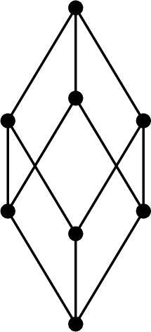
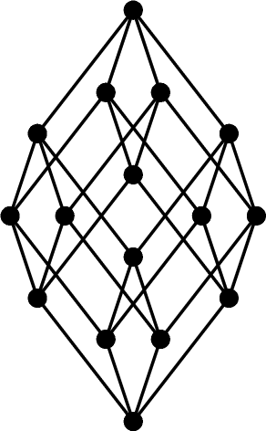
As another example we present the contra nominal scales on objects and attributes, i.e., where . It is easy to see that these exhibit order dimension . We show line diagrams of the concept lattices computed by DimDraw for the two, three, and four dimensional contra nominal scales in Figure 1.

We conclude this section by comparing our tool to previous results in [2]. There the author employed an approach to generate additive line diagrams (left). We may note that our drawing (middle) is not additive, however, it resembles the hand drawn additive diagram (right) more accurately.
![[Uncaptioned image]](/html/1903.00686/assets/ganter_generated.png)
![[Uncaptioned image]](/html/1903.00686/assets/ganter.png)
![[Uncaptioned image]](/html/1903.00686/assets/ganter_hand.png)
2.0.2 Outlook
In this work we demonstrated a novel approach for drawing lattice diagrams automatically, which resulted in the work-in-progress software DimDraw. This tool will be part of the upcoming version of conexp-clj (https://github.com/exot/conexp-clj). The ongoing research for more sophisticated projection theories, as used by this tool, will be extended in future publications.
References
- [1] R. Freese “Automated Lattice Drawing” In Concept Lattices 2961, LNCS Berlin/Heidelberg: Springer, 2004, pp. 112–127 URL: http://dx.doi.org/10.1007/978-3-540-24651-0_12
- [2] B. Ganter “Conflict Avoidance in Additive Order Diagrams” In Journal of Universal Computer Science, 10.8, 2004, pp. 955–966 URL: http://www.jucs.org/jucs_10_8/conflict_avoidance_in_additive/Ganter_B.pdf
- [3] B. Ganter and R. Wille “Formal Concept Analysis: Mathematical Foundations” Springer-Verlag, Berlin, 1999, pp. x+284
- [4] R. Wille “Lattices in Data Analysis: How to Draw Them with a Computer” In Algorithms and Order Dordrecht: Springer Netherlands, 1989, pp. 33–58 DOI: 10.1007/978-94-009-2639-4_2
- [5] J. Yáñez and J. Montero “A poset dimension algorithm” In Journal of Algorithms 30.1 Elsevier, 1999, pp. 185–208