Strain control of the Néel vector in Mn-based antiferromagnets
Abstract
Control of the Néel vector in antiferromagnetic materials is one of the challenges preventing their use as active device components. Several methods have been investigated such as exchange bias, electric current, and spin injection, but little is known about strain-mediated anisotropy. This study of the antiferromagnetic L10-type MnX alloys MnIr, MnRh, MnNi, MnPd, and MnPt shows that a small amount of strain effectively rotates the direction of the Néel vector by 90∘ for all of the materials. For MnIr, MnRh, MnNi, and MnPd, the Néel vector rotates within the basal plane. For MnPt, the Néel vector rotates from out-of-plane to in-plane under tensile strain. The effectiveness of strain control is quantified by a metric of efficiency and by direct calculation of the magnetostriction coefficients. The values of the magnetostriction coefficients are comparable with those from ferromagnetic materials. These results indicate that strain is a mechanism that can be exploited for control of the Néel vectors in this family of antiferromagnets.
There has been a rapidly increasing interest in the use of antiferromagnetic (AFM) materials for use as active device elements Baltz et al. (2018); Gomonay, Jungwirth, and Sinova (2017); Jungwirth et al. (2016). AFMs are insensitive to parasitic electromagnetic and magnetic interference. The dipolar coupling is minimal, since there is no net magnetic moment. Their lack of macroscopic magnetic fields allows AFM devices and interconnects to be highly scaled with reduced cross talk and insensitivity to geometrical anisotropy effects. AFM resonant frequencies and magnon velocities are several orders of magnitude higher than those in ferromagnetic materials, and these velocities correlate with similarly higher switching speeds Gomonay and Loktev (2014); Jungwirth et al. (2016); Grezes et al. (2016). AFM metals and insulators are plentiful, and many have Néel temperatures well above room temperature, a requirement for compatibility with on-chip temperatures in current Si integrated circuits.
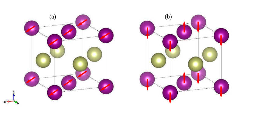
The high Néel temperatures of the Mn-based equiatomic alloys such as MnIr, MnRh, MnNi, MnPd, and MnPt make them suitable candidates for on-chip applications Baltz et al. (2018). Extensive research has been conducted on the electronic Sakuma (1998); Umetsu, Fukamichi, and Sakuma (2002); Umetsu et al. (2004); Umetsu, Fukamichi, and Sakuma (2006, 2007), magnetic Pál et al. (1968); Sakuma (1998); Umetsu, Fukamichi, and Sakuma (2006, 2007), and elastic properties Wang et al. (2013a, b) of these materials. The spins on the Mn atoms are antiferromagnetically coupled with each other in the basal plane, and each plane is coupled ferromagnetically as shown in Fig. 1.
The positive attributes of speed, scaling, and robustness to stray fields are accompanied by the challenges of manipulating and detecting the antiferromagnetic states. There are several methods to control the magnetic properties of AFM materials such as with exchange bias Baltz et al. (2018), the use of electric current Wadley et al. (2016), and strain induced by a piezoelectric material Barra et al. (2018); Yan et al. (2019). The recent experimental demonstration of strain control of the Néel vector in MnPt Yan et al. (2019), provides timely motivation for a theoretical study of strain-meditated magnetic anisotropy in the MnX AFM materials. Density functional theory (DFT) is used to analyze the effect of strain on the magnetic anisotropy. The effectiveness of strain control is quantified by a metric of efficiency and by calculation of the magnetostriction coefficients.
| a (Å) | b (Å) | c (Å) | () | |
|---|---|---|---|---|
| MnIr | 3.84 | 3.84 | 3.64 | 2.8 |
| MnRh | 3.85 | 3.85 | 3.62 | 3.1 |
| MnNi | 3.62 | 3.62 | 3.58 | 3.2 |
| MnPd | 3.99 | 3.99 | 3.69 | 3.8 |
| MnPt | 3.98 | 3.98 | 3.71 | 3.7 |
First principles calculations are performed as implemented in the Vienna Ab initio Simulation Package (VASP) Kresse and Hafner (1993) to investigate the effect of strain on the magnetic anisotropy of L10-ordered bulk MnIr, MnRh, MnNi, MnPd, and MnPt. Projector augmented-wave (PAW) potentials Blöchl (1994) and the generalized gradient approximation (GGA) parameterized by Perdew-Burke-Ernzerhof (PEB) were employed Perdew, Burke, and Ernzerhof (1996). Depending on the materials, different cut-off energies (typically ranging from 420 eV to 450 eV) and k-points grids were used in order to ensure the total energy converged within 10-7 eV per unit cell. The initial equilibrium structure consists of a tetragonal unit cell where the fractional coordinates of Mn atoms are (0, 0, 0) and (0.5, 0.5, 0), and those of the X atoms are (0.5, 0, 0.5) and (0, 0.5, 0.5). Compressive or tensile stress along the axis is applied to each structure, and the structure is fully relaxed along the and axes (biaxially) until all forces on each atom are less than 10-4 eVÅ-1. The relaxed lattice constants for each applied strain are shown in supplementary Fig. S1. The strain is defined as, , where and are the lattice constants with and without strain, respectively. With the relaxed structure, the spin-polarized self-consistent calculation is performed to obtain the charge density. Finally, the magnetic anisotropy energies are determined by calculating the total energies for different Néel vector directions including spin orbit coupling. Table 1 shows the lattice constants and the magnetic moments of the Mn site in MnX without strain. All of the values are very close to those from previous results Wang et al. (2013a, b). The local magnetic moments of the X site are zero for all materials.
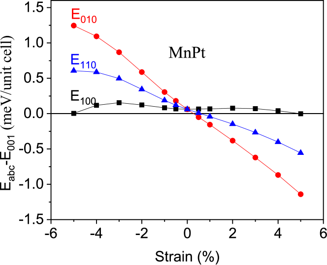
Figures 2–6 show the differences in the total energies as a function of the strain for MnIr, MnRh, MnNi, MnPd, and MnPt, respectively, where is the ground state energy with the Néel vector along the direction. The reference energy levels from each figure, which are indicated by the solid black lines, are for MnPt and for the other materials. The reference energies are the lowest energy state, which means MnIr, MnRh, MnNi, and MnPd have in-plane anisotropy and MnPt has out-of-plane anisotropy without strain. This is consistent with experimental results Pál et al. (1968). To show the energy differences more clearly as the strain changes, the reference level is taken at each value of the applied strain. At zero strain, there is no energy difference between and because of the symmetry of all of the materials.
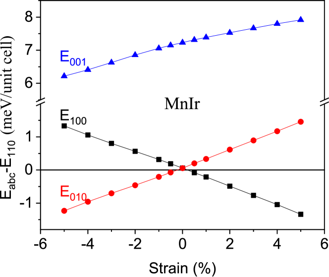
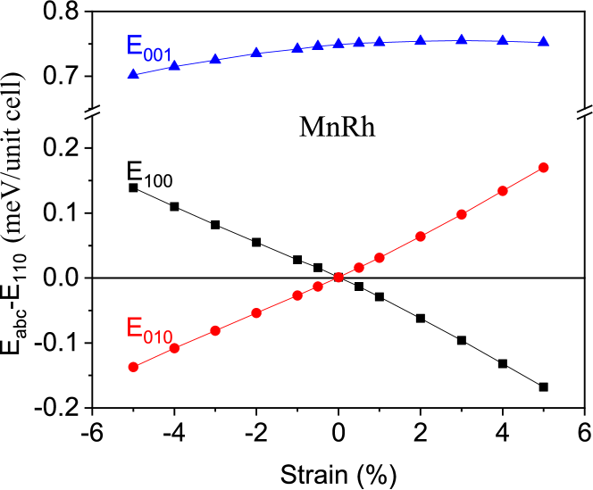
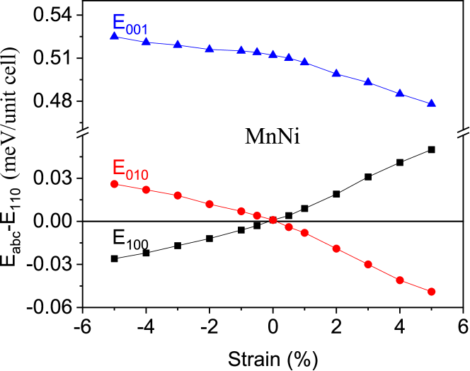
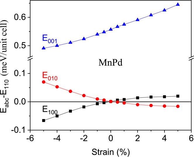
Figures 2–5 show that sweeping the strain from negative (compressive) to positive (tensile) causes a 90∘ rotation of the Néel vector in the -plane for the four materials MnIr, MnRh, MnNi, and MnPd. However, the alignment of the Néel vector with compressive or tensile strain depends on the specific material. MnIr and MnRh behave like magnets with a positive magnetostriction coefficient, since tensile strain along [100] causes the Néel vector to align in the [100] direction. On the other hand, MnNi and MnPd behave like magnets with a negative magnetostriction coefficient, since tensile strain along [100] causes the Néel vector to align in the [010] direction Biswas, Bandyopadhyay, and Atulasimha (2014).
MnPt is unique among the 5 materials. In equilibrium, in the absence of strain, the Néel vector has perpendicular anisotropy. Under compressive (negative) strain along the axis, the Néel vector remains out-of-plane. Under tensile strain along , the Néel vector switches from out-of-plane to in-plane aligning in the direction.
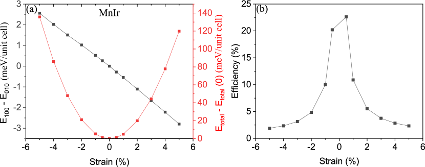
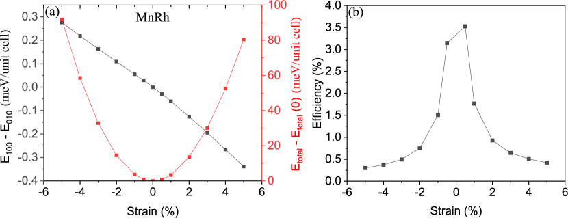
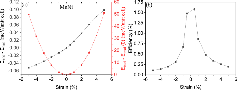

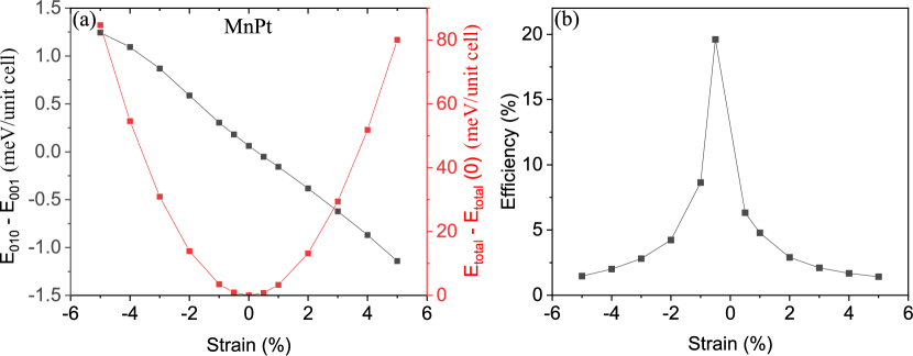
For applications, it is useful to quantify the efficiency with which strain rotates the Néel vector and to determine the magnetostriction coefficient from the ab initio calculations. The internal efficiency is defined as
| (1) |
where the total energies and are defined in the same way as above, i.e. the total energies in the presence of strain with the Néel vector oriented along or , respectively. The denominator in the Eq. (1) is the total energy change induced by the strain. For MnIr, MnRh, MnNi, and MnPd, and are and , respectively. For MnPt, and are and , respectively. The numerator and denominator of Eq. (1) are plotted as a function of strain in Figs. 7-11(a), and the resulting efficiencies are plotted as a function of strain in Figs. 7-11(b). The changes in the total energies, shown as red curves in Figs. 7-11(a), are parabolic so that they can be considered as the strain energy proportional to the square of the applied strain. On the other hand, the differences between two energies (the black curves in Figs. 7-11(a)) are approximately linear under small strain (). Therefore, the efficiency decreases sharply as the amount of strain increases. At strain, the highest efficiency for in-plane rotation of the Néel vector is for MnIr. For MnRh, MnNi, and MnPd, the efficiencies are smaller and equal to , , and , respectively. To rotate the Néel vector from out-of-plane to in-plane in MnPt, a positive, tensile strain must be applied. The efficiency of this process at strain is .
Using the data above, the magnetostriction coefficients (), which are widely used in ferromagnets, are calculated. The magnetostriction coefficient is defined as
| (2) |
where and are Young’s modulus and strain, respectively Bur et al. (2011). is the magnetoelastic anisotropy constant, which is defined as the difference of the magnetic anisotropy energies with and without strain, and the magnetic anisotropy energy is defined as . Plots of as a function of strain are shown in Supplementary Fig. S2. Young’s moduli for all MnX alloys except MnIr were adopted from previous calculation results Wang et al. (2013a, b), and the value for MnIr was determined as described in the Supplementary Information. For simplicity, we disregard which represents a negligible change in the lattice constant along the -axis caused by the applied strain along . The results for are summarized in the Table 2. As expected, MnIr and MnRh have positive values of , and MnNi, MnPd, and MnPt have negative values. Also, the magnitudes of the magnetostriction coefficients follow the magnitudes of the efficiencies. The magnetostriction coefficients of the MnX alloys are comparable with the ones from ferromagnets Clark et al. (2000); Panduranga et al. (2018); Hall (1959); Huang et al. (1995); Fritsch and Ederer (2012), which suggests that strain can be used to control the magnetic anisotropy of these antiferromagnetic materials.
| MnIr | MnRh | MnNi | MnPd | MnPt | |
|---|---|---|---|---|---|
| (ppm) | 241 | 43 | -15 | -17 | -196 |
In summary, the Néel vectors of MnIr, MnRh, MnNi, and MnPd can be rotated in the basal plane by applying in-plane strain. MnIr and MnRh behave like magnets with positive magnetostriction coefficients, since their Néel vectors align with tensile strain. MnNi and MnRh behave like magnets with negative magnetostriction coefficients, since their Néel vectors align with compressive strain. The internal efficiency of this process is highest for MnIr and it is equal to at strain. MnPt is unique among the 5 alloys in that its Néel vector aligns out-of-plane along the [001] axis in equilibrium. Applying a tensile strain along [100] rotates the Néel vector from out-of-plane [001] to in-plane [010]. The efficiency of this process at tensile strain is . Under compressive strain along [100], the Néel vector of MnPt remains out-of-plane [001]. The magnitudes of the calculated magnetostriction coefficients are comparable with those of ferromagnets, and they follow the same trends as the calculated efficiencies. For in-plane rotation of the Néel vector, MnIr has the highest magnetostriction coefficient of 241 ppm. The magnetostriction coefficient for out-of-plane rotation in MnPt is -196 ppm. These results suggest that strain can be an effective mechanism to control the Néel vectors in this family of antiferromagnets.
This work was supported as part of Spins and Heat in Nanoscale Electronic Systems (SHINES) an Energy Frontier Research Center funded by the U.S. Department of Energy, Office of Science, Basic Energy Sciences under Award #DE-SC0012670. This material is based upon work supported by or in part by the U.S. Army Research Laboratory and the U.S. Army Research Office under Grant No. W911NF-17-0364. This work used the Extreme Science and Engineering Discovery Environment (XSEDE) Towns et al. (2014), which is supported by National Science Foundation Grant No. ACI-1548562 and allocation ID TG-DMR130081.
References
- Baltz et al. (2018) V. Baltz, A. Manchon, M. Tsoi, T. Moriyama, T. Ono, and Y. Tserkovnyak, Rev. Mod. Phys. 90, 015005 (2018).
- Gomonay, Jungwirth, and Sinova (2017) O. Gomonay, T. Jungwirth, and J. Sinova, Physica Status Solidi (RRL) Rapid Research Letters 11, 1700022 (2017).
- Jungwirth et al. (2016) T. Jungwirth, X. Marti, P. Wadley, and J. Wunderlich, Nature Nanotechnology 11, 231 (2016).
- Gomonay and Loktev (2014) E. V. Gomonay and V. M. Loktev, Low Temperature Physics 40, 17 (2014).
- Grezes et al. (2016) C. Grezes, F. Ebrahimi, J. G. Alzate, X. Cai, J. A. Katine, J. Langer, B. Ocker, P. K. Amiri, and K. L. Wang, Appl. Phys. Lett. 108, 012403 (2016).
- Sakuma (1998) A. Sakuma, Journal of Magnetism and Magnetic Materials 187, 105 (1998).
- Umetsu, Fukamichi, and Sakuma (2002) R. Y. Umetsu, K. Fukamichi, and A. Sakuma, Journal of magnetism and magnetic materials 239, 530 (2002).
- Umetsu et al. (2004) R. Y. Umetsu, M. Miyakawa, K. Fukamichi, and A. Sakuma, Physical Review B 69, 104411 (2004).
- Umetsu, Fukamichi, and Sakuma (2006) R. Y. Umetsu, K. Fukamichi, and A. Sakuma, Materials transactions 47, 2 (2006).
- Umetsu, Fukamichi, and Sakuma (2007) R. Y. Umetsu, K. Fukamichi, and A. Sakuma, Journal of the Physical Society of Japan 76, 104712 (2007).
- Pál et al. (1968) L. Pál, E. Krén, G. Kádár, P. Szabó, and T. Tarnóczi, Journal of Applied Physics 39, 538 (1968).
- Wang et al. (2013a) J. Wang, Z. Jiang, W. Chen, X. Zhang, and B. Zhou, Intermetallics 34, 83 (2013a).
- Wang et al. (2013b) J. Wang, A. Gao, W. Chen, X. D. Zhang, B. Zhou, and Z. Jiang, Journal of Magnetism and Magnetic Materials 333, 93 (2013b).
- Wadley et al. (2016) P. Wadley, B. Howells, J. Železnỳ, C. Andrews, V. Hills, R. P. Campion, V. Novák, K. Olejník, F. Maccherozzi, S. S. Dhesi, et al., Science 351, 587 (2016).
- Barra et al. (2018) A. Barra, J. Domann, K. W. Kim, and G. Carman, Physical Review Applied 9, 034017 (2018).
- Yan et al. (2019) H. Yan, Z. Feng, S. Shang, X. Wang, Z. Hu, J. Wang, Z. Zhu, H. Wang, Z. Chen, H. Hua, et al., Nature Nanotechnology 14, 131 (2019).
- Kresse and Hafner (1993) G. Kresse and J. Hafner, Physical Review B 47, 558 (1993).
- Blöchl (1994) P. E. Blöchl, Physical Review B 50, 17953 (1994).
- Perdew, Burke, and Ernzerhof (1996) J. P. Perdew, K. Burke, and M. Ernzerhof, Physical Review Letters 77, 3865 (1996).
- Biswas, Bandyopadhyay, and Atulasimha (2014) A. K. Biswas, S. Bandyopadhyay, and J. Atulasimha, Applied Physics Letters 104, 232403 (2014).
- Bur et al. (2011) A. Bur, T. Wu, J. Hockel, C. J. Hsu, H. K. D. Kim, T. K. Chung, K. Wong, K. L. Wang, and G. P. Carman, Journal of Applied Physics 109, 123903 (2011).
- Clark et al. (2000) A. E. Clark, J. B. Restorff, M. Wun-Fogle, T. A. Lograsso, and D. L. Schlagel, IEEE Transactions on Magnetics 36, 3238 (2000).
- Panduranga et al. (2018) M. K. Panduranga, T. Lee, A. Chavez, S. V. Prikhodko, and G. P. Carman, AIP Advances 8, 056404 (2018).
- Hall (1959) R. C. Hall, Journal of Applied Physics 30, 816 (1959).
- Huang et al. (1995) J. Huang, C. Prados, J. E. Evetts, and A. Hernando, Physical Review B 51, 297 (1995).
- Fritsch and Ederer (2012) D. Fritsch and C. Ederer, Physical Review B 86, 014406 (2012).
- Towns et al. (2014) J. Towns, T. Cockerill, M. Dahan, I. Foster, K. Gaither, A. Grimshaw, V. Hazlewood, S. Lathrop, D. Lifka, G. D. Peterson, et al., Computing in Science & Engineering 16, 62 (2014).