A controllable superconducting electromechanical oscillator with a suspended membrane
Abstract
We fabricate a microscale electromechanical system, in which a suspended superconducting membrane, treated as a mechanical oscillator, capacitively couples to a superconducting microwave resonator. As the microwave driving power increases, nonmonotonic dependence of the resonance frequency of the mechanical oscillator on the driving power has been observed. We also demonstrate the optical switching of the resonance frequency of the mechanical oscillator. Theoretical models for qualitative understanding of our experimental observations are presented. Our experiment may pave the way for the application of a mechanical oscillator with its resonance frequency controlled by the electromagnetic and/or optical fields, such as a microwave-optical interface and a controllable element in a superqubit-mechanical oscillator hybrid system.
There are intensive efforts for interfacing the microwave and optical domains by using various systems including the opto-electro-mechanical systems Wang and Clerk (2012); Tian (2012); Bochmann et al. (2013); Andrews et al. (2014); Higginbotham et al. (2018), solid-state spins in resonators O’Brien et al. (2014); Williamson et al. (2014); Xia and Twamley (2015), molecules or spins coupled to a nanowaveguide Das et al. (2017); Xia et al. (2018), electro-optical material-based Whispering Gallery mode resonator Rueda et al. (2016) or cold atoms Han et al. (2018). Among these approaches, the opto-electro-mechanical system is of particular interest because it is efficient in signal conversion and can be integrated on a chip.
In the opto-electro-mechanical resonator, the core element is the mechanical oscillator, which has been attractive for its promising applications in both classical and quantum regimes Ekinci and Roukes (2005); Poot and van der Zant (2012); Aspelmeyer et al. (2014). The features of mechanical oscillators have been engineered by using various materials and structures. One of the main characteristics of a mechanical oscillator is its resonance frequency, which is determined by its parameters such as the mass, the geometric shapes and dimensions and the spring constant. These parameters are almost unchangeable after the sample is fabricated. In order to control the resonance frequency, an electrostatic field is usually applied to in situ change the tension of the mechanical oscillator Kozinsky et al. (2006); Parmar et al. (2015); Willick et al. (2017). However adding the controlling component such as the electrostatic electrode to the structure of the mechanical oscillator greatly improves the complexity and difficulty of the whole micro-fabrication process.
In this letter we report an experimental implementation of controlling the resonance frequency of a mechanical oscillator with microwave and optical fields instead of the electrostatic field. We fabricate a microscale electromechanical system composed of a microwave coplanar waveguide (CPW) resonator and a mechanical oscillator, which is a suspended membrane. Under a microwave driving to the microwave subsystem, we observe a nonlinear and nonmonotonic frequency shift of the mechanical subsystem due to the radiation pressure force of the field. Also we use a laser beam pressing the mechanical part to modify its resonance frequency. Because the microwave signal passing through the microwave resonator is modulated by the motion of the mechanical oscillator, we demonstrate the switching on/off of the transmission of the sidebands of the microwave signal, which is a step towards bridging the microwave and optical signals without an optical cavity. The experimental observations are qualitatively reproduced with our theoretical models.
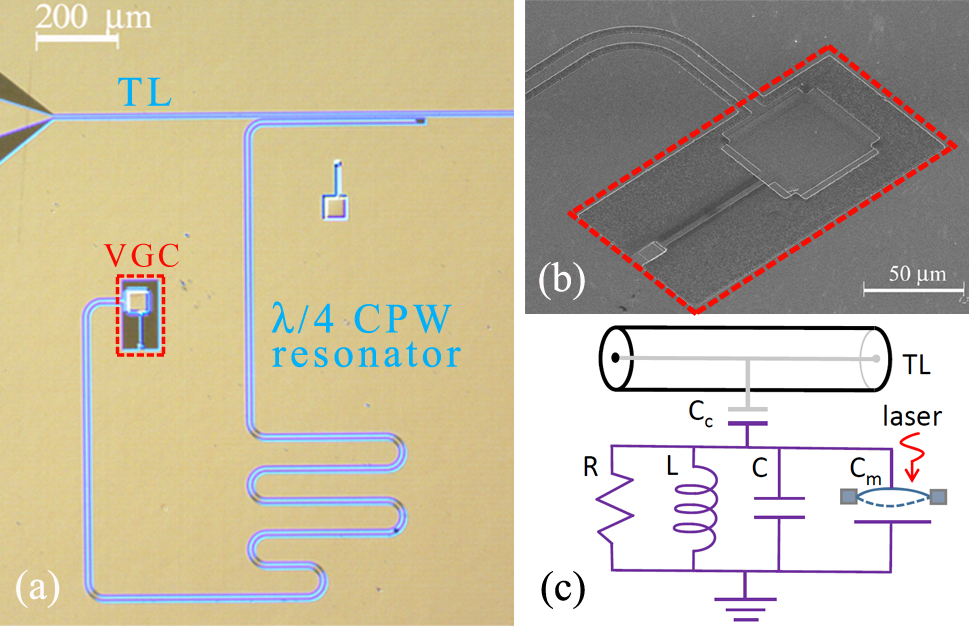
The optical photograph of our sample is shown in Fig. 1(a). A /4 microwave CPW resonator is capacitively coupled to a transmission line on one end and is terminated by the a vacuum-gap capacitor (VGC) Cicak et al. (2010); Teufel1 et al. (2011); Suh et al. (2014) (see Fig. 1(b)) on the other end. The sample is made from aluminum on the high-resistivity silicon substrate evaporated in a multi-chamber evaporation system with ultra-high vacuum. The main fabrication procedure includes three steps: (1) Fabricating the lower electrode plate of VGC by lift-off process. (2) Preparing the sacrificial layer by using diluted S1813 UV photoresist. (3) Forming the rest of the circuit, including the top electrode plate of VGC, the CPW resonator and the CPW feed lines by wet-etching after depositing another layer of -thick aluminum film. The fabricated device is equivalent to an electric circuit with a mechanical oscillator shown in Fig. 1(c). The CPW resonator couples to the transmission line with characteristic impedance of via a capacitor of f F . The value of VGC is determined approximately by , where is the permittivity of vacuum, is the membrane area and is the vacuum gap between the top and lower plates of VGC. The gap can be adjusted in the process of fabrication and later be tuned with the microwave and optical field. The displacement of the fundamental vibration mode of the square membrane is a spatial function given by
| (1) |
where and are the length and width of the suspended membrane, respectively, and the spatial ranges of vibration are and , and is the oscillation amplitude. The fundamental-mode frequency is evaluated as , where and are the tension per unit length and mass per unit area, respectively.
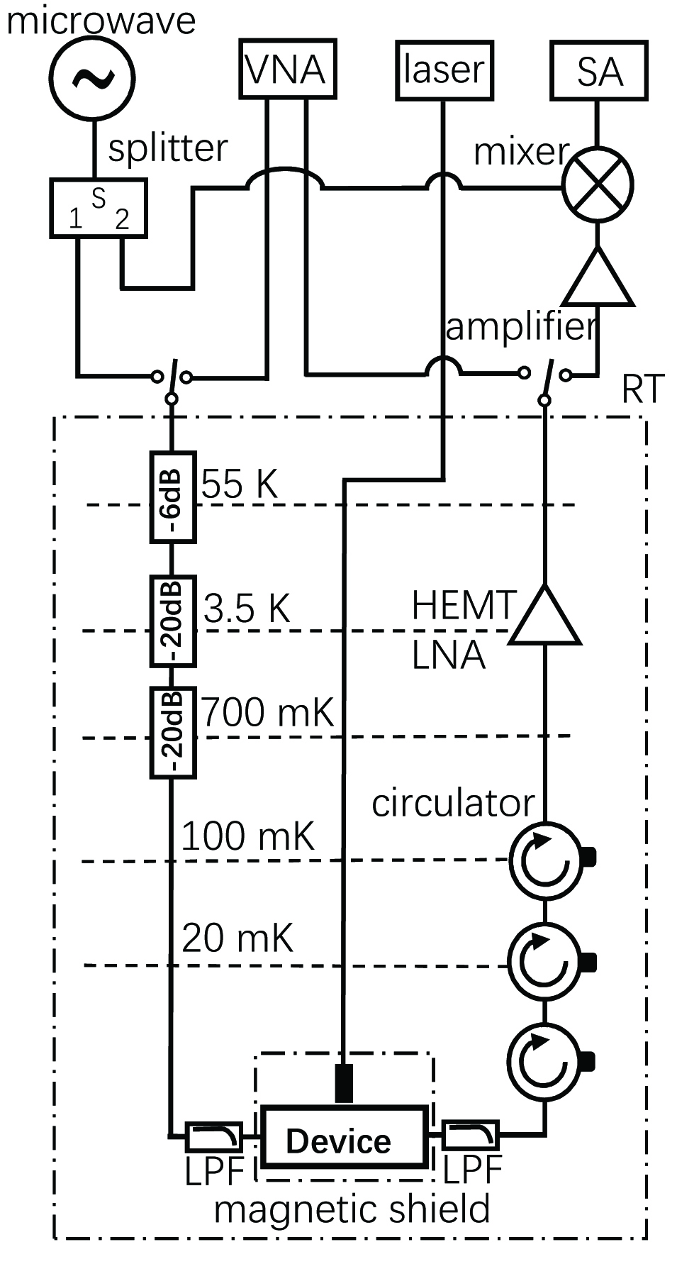
The device is located in an Oxford Triton 400 dilution refrigerator below m K , with magnetic shielding at both mK and room temperature (see Fig. 2). To suppress the background noise from the higher-temperature parts, the microwave field input to the device is heavily attenuated at each stage of the dilution refrigerator and filtered by low-pass filters with a cutoff frequency of . The output signal from the microwave resonator first passes through microwave circulators at cryogenic temperature to reject the back-action noise from amplifiers. Then, it is amplified by a low-noise amplifier and microwave amplifiers at room temperature, respectively Pan et al. (2017). The low-noise amplifier uses a high-electron-mobility transistor located in the dilution refrigerator. A vector network analyzer is used to measure the transmission characteristics of the device. To measure the resonance frequency of the mechanical oscillator, we use frequency down-conversion technology as described below: The input microwave signal is divided into two paths. One of the paths is fed into the cryostat and the other one is for the local reference signal of a mixer. This mixer works as a frequency down-converter for the amplified output microwave signal which is modulated by the mechanical oscillator. The down-converted signal is then measured by a spectrum analyzer. We apply a n m laser, generated by a semiconductor diode laser source, to the mechanical oscillator to control its resonance frequency, thus switch on/off the microwave sideband signals arising from the modulation of the mechanical oscillator.
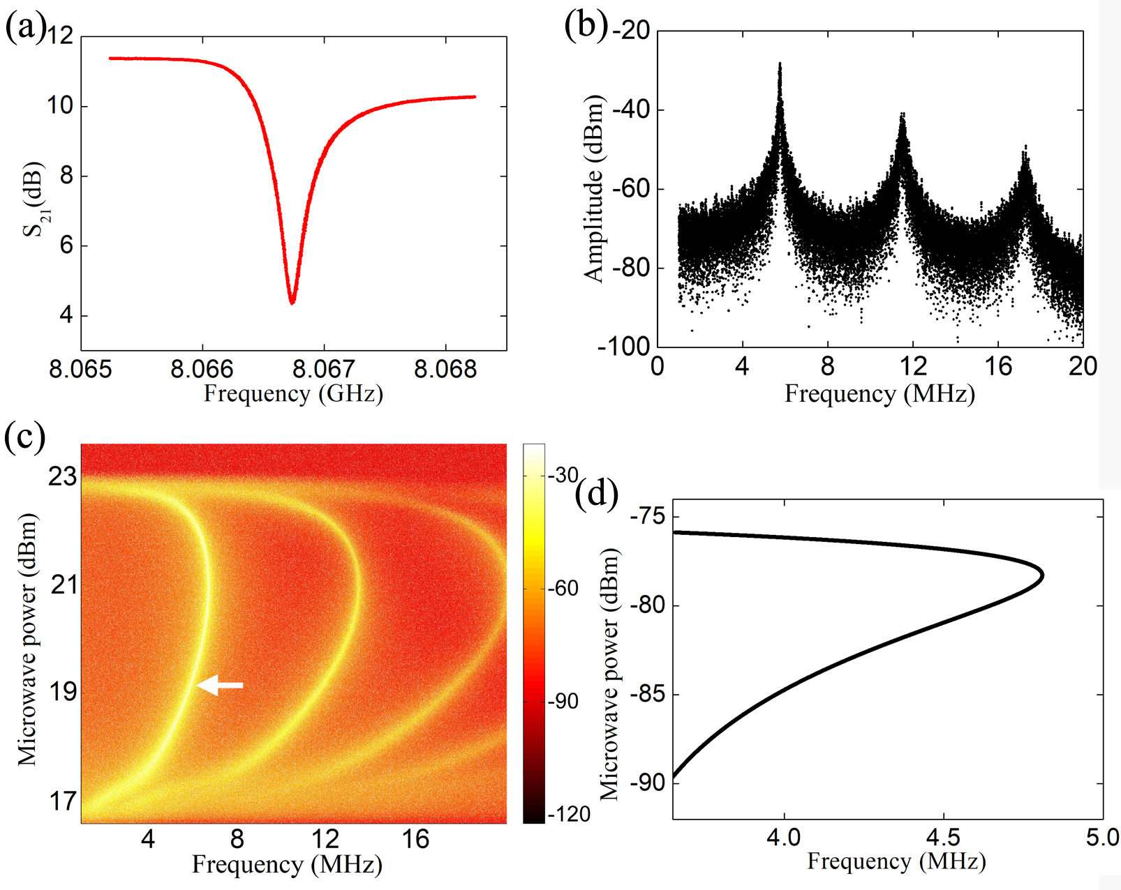
The transmission characteristic of the CPW resonator is measured by a vector network analyzer shown in Fig. 3(a). Clearly, a dip appears at the resonance frequency of . In our device, the impedance of the CPW resonator is given by
| (2) |
where is the VGC impedance, is the characteristic impedance of the CPW resonator and is the propagation constant of microwave field in the vicinity of the resonance frequency. Under the superconducting condition and neglecting the loss, the propagation constant approximates to the phase constant. is the physical length of the CPW resonator. Using , µ m and rad / m , we obtain p F , in consistence with the estimate from the fabrication parameters.
After obtaining the resonant frequency of the superconducting microwave CPW resonator, we measure the frequency of the mechanical oscillator using the frequency down-conversion technology as described previously. As shown in Fig. 3(b), with an input microwave power of 19 dBm at room temperature, three evenly spaced peaks appear at M Hz , M Hz and M Hz , respectively. Note that the lowest frequency M Hz is the resonance frequency of the mechanical fundamental mode. The higher frequencies correspond to the higher-order harmonics of the fundamental mode. These harmonics are caused by the nonlinear conversion of the microwave resonator system Rokhsari et al. (2005). The dependence of the fundamental-mode frequency and its harmonics on the input microwave power are obtained by scanning the input microwave power. Hereafter we focus on the fundamental-mode frequency. It can be seen from Fig. 3(c) that the fundamental-mode frequency of mechanical oscillator increases first from about M Hz to a maximum MHz and then decreases rapidly as the input power increases further.
The observed nonmonotonic frequency shift of the mechanical oscillator can be understood by treating the device as an electromechanical resonator. Its motion is governed by the Hamiltonian ref (2010)
| (3a) | ||||
| (3b) | ||||
| (3c) | ||||
| (3d) | ||||
where is the resonance frequency of the microwave resonator, and are the effective mass and the resonance frequency of the mechanical oscillator, and are the mechanical momentum and displacement operators, and are the annihilation and creation operators of the microwave resonator. is the corresponding photon-number operator. The input photon flux is determined by the driving amplitude as , related to the input power . The microwave resonator is driven by a microwave field with frequency , yielding a detuning . The single-photon coupling rate of the electromechanical oscillator is . For our device, , where n m . When considering the effective displacement of the whole area of the membrane, we have . In a realistic experiment, can be even smaller. We use a rough estimate of M Hz / n m . The microwave loss of the system includes two contributions: one due to the coupling to the input and output channel yielding a decay rate , the other from the intrinsic loss causing a decay rate . For simplicity, we consider the critical-coupling case, i.e. .
For a constant driving leading to all time derivatives () vanishing small, we can find the stable solutions and that ref (2010)
| (4a) | |||
| (4b) | |||
where . Due to the displacement, the detuning now becomes . By calculating the effective mechanical susceptibility, we obtain the effective resonance frequency of the mechanical subsystem under the driving as
| (5) |
where
| (6) |
In our case, the driving is strong that the frequency change of the mechanical subsystem can be even larger than its free oscillation frequency . As a result, the commonly applied fluctuation approximation, i.e. , breaks. The effective frequency can be found by numerically solving the joint Eq. 4 and then substituting the solution into Eq. 6. In fact, when the input power increases, the intra-cavity photon number increases, and so does the displacement . Thus, the value of decreases rapidly. For a certain input power, the frequency reaches its maximum. Crossing this point, approaches zero. As a result, the effective frequency reduces to a small value. Thus the effective frequency has a nonmonotonic dependence on the input power as observed in our experiment, which is also confirmed by the theoretical result in Fig. 3(d). It can be clearly seen from Fig. 3(d) that, by treating the device as a simple electromechanical resonator and using G Hz , M Hz , , , M Hz / n m and p g , we reproduce qualitatively the nonmonotonic frequency shift of the mechanical oscillator as the driving power increases. Due to the difficulty in the calibration on the power entering the microwave resonator, the input power in our model is different from the experimental data which is a nominal value at room temperature.
Then fixing the input microwave power at 19.2 dBm as schematically illustrated by the white arrow in Fig. 3(c), we apply a n m laser beam from a semiconductor diode to the suspended membrane. As shown in Fig. 4(a), we experimentally observe the laser-induced mechanical frequency shift. When the laser power increases, the mechanical fundamental-mode frequency deceases from M Hz to M Hz and then increase to M Hz , wich also displays a nonmonotonic change. The first- and second-order harmonics show similar nonmonotonic behavior. Due to the difficulty in the calibration of the optical power, we use the arbitrary unit in the y-axis.
To understand this optically-induced frequency shift, we consider an optical pressure on the suspended membrane of the electromechanical system. Unlike typical optomechanical system ref (2010), our model has an external force from the laser beam and the equation of motion of the mechanical oscillator with a microwave probe takes the form
| (7) |
where is the optical force on the mechanical oscillator applied by the control laser beam with power , is a coefficient describing how effective the laser pressure acts on the moving part, and is the mechanical decay rate. Here we simply set . indicates the intra-cavity photon number. is the vacuum light velocity. With this light force considered, the stable solutions, and , for the cavity mode and the mechanical displacement are determined by the joint equations
| (8a) | |||
| (8b) | |||
Substituting the solutions into Eq. 5, we obtain the effective mechanical resonance frequency under the laser pressure. The force attributed to the laser beam is equivalent to the radiation pressure from the microwave CPW resonator. It also strongly modulates the mechanical resonance frequency. In this configuration, the mechanical oscillator vibrates initially at a resonance frequency, biased by the microwave input. When the laser beam is weak, the microwave radiation force is dominant. As the laser power increases, the light pressure presses the membrane and becomes larger and larger. Thus, the effective detuning, increases. As a result, the intra-cavity photon number rapidly reduces, leading to smaller radiation force from the microwave field. When the laser beam is weak, the microwave radiation force is dominant and the total force on the membrane reduces. Thus the effective resonance frequency of the mechanical oscillator decreases rapidly. At a certain laser power, the frequency reaches its minimum. When the laser power increases further to become dominant over the microwave radiation force, the total force pressing the membrane increases again. Thus the effective mechanical resonance frequency increases but at a smaller rate. For a very strong laser beam, both the light pressure and the displacement increases at constant rates, resulting in the saturation of . Numerically solving Eq. 8, we find the effective mechanical resonance frequency as a function of a constant laser power. As shown in Fig. 4(b), our theoretical model reproduces well the frequency shift of the mechanical oscillator taking G Hz , M Hz , M Hz , M Hz / n m , p g and . and change a little in comparison with those used in understanding the microwave-power-dependent frequency shift. One of the reasons may be the simultaneous injection of the laser and the higher-power microwave to the mechanical oscillator.
With the laser, we can optically control the sideband signals of the probe microwave field in our device. The key idea is to apply a temporally modulated laser beam to the movable membrane and thus to change the capacitor . In doing so, we dynamically modulate the resonance frequency of the microwave CPW resonator and subsequently its sideband signals. Experimentally, a rectangular voltage pulse is used to modulate the laser power. When the rectangular voltage pulse is on a high level, a laser beam is applied to press the suspended membrane. This pressure causes a frequency shift to the mechanical resonator, and thus the sideband signals of the resonant frequency in the microwave CPW resonator. The duration of such “on”-state laser beam is controlled by the duty ration of the rectangular voltage pulse. The spectrum of down-converted microwave sideband signal is presented in Fig. 4(c). The fundamental-mode frequency shifts from M Hz to M Hz , when the laser is tuned from the “off” state to “on”, corresponding to the laser power being 0 and as shown in Fig. 4(a), respectively. We can switch on/off the microwave sideband signal output from the microwave CPW resonator with an extinction ratio of .
Figure 4(d) shows the switching temporal distribution of the transmitted “on”-state sideband signal with the mechanical fundamental-mode frequency of M Hz . This signal is switched from the “off”-state signal, corresponding to the sideband field modulated by the lower mechanical fundamental-mode frequency of M Hz . A time counter is triggered to start timing with the synchronization output of the pulse generator, which modulates the laser beam. The amplified down-converted signal is filtered with a bandpass filter through which only the signal associated with the mechanical fundamental-mode frequency of M Hz can pass. This filtered signal is then sent to the time counter to stop timing. We perform measurements for each repetition rate of the laser pulse to obtain the corresponding switching time statistic distribution. The highest repetition rate is at least k Hz , which is limited by the modulation rate of our laser. The average irradiation force of laser beam increases as the rectangular pulse repeats faster. If there is heating effect due to the laser, the mechanical resonant frequency will change Teufel et al. (2008). In this case, the distribution will also change and even vanish as the repetition rate of laser pulse increases. However, as seen from Fig. 4(c)(d), little difference is observed in the distributions and the line width of the mechanical resonator when the repetition rate increases from Hz to k Hz . Therefore, the heat effect due to the laser is not observable with the measuring accuracy in our experiment.
To summarize, we fabricate a superconducting electromechanical system and modulate its mechanical frequency with both the microwave and optical fields. We first drive the microwave resonator strongly with the microwave field and observe large but nonmonotonic mechanical frequency shifts. By applying a laser beam to the mechanical membrane, we further demonstrate the optical control of the mechanical frequency and thus the transmission of the sideband signals of the microwave through the microwave CPW resonator. The developed device may work as an interface for microwave and optical domains. Also, the scenario demonstrated here has the potential in controlling a superconducting qubit coupled to a mechanical oscillator Cicak et al. (2010); Teufel et al. (2008); LaHaye et al. (2009); Pirkkalainen et al. (2013); Bosman et al. (2017) with lasers mediated by an optically modulated capacitor.
This work was partially supported by the NKRDP of China (Grant Nos. 2016YFA0301801, 2017YFA0303703), NSFC (Grant Nos. 11474154,61521001,11874212,11574145), PAPD, and Dengfeng Project B of Nanjing University.
References
- Wang and Clerk (2012) Y.-D. Wang and A. A. Clerk, Phys. Rev. Lett. 108, 153603 (2012).
- Tian (2012) L. Tian, Phys. Rev. Lett. 108, 153604 (2012).
- Bochmann et al. (2013) J. Bochmann, A. Vainsencher, D. D. Awschalom, and A. N. Cleland, Nat. Phys. 9, 712 (2013).
- Andrews et al. (2014) R. W. Andrews, R. W. Peterson, T. P. Purdy, K. Cicak, R. W. Simmonds, C. A. Regal, and K. W. Lehnert, Nat. Phys. 10, 321 (2014).
- Higginbotham et al. (2018) A. P. Higginbotham, P. S. Burns, M. D. Urmey, R. W. Peterson, N. S. Kampel, B. M. Brubaker, G. Smith, K. W. Lehnert, and C. A. Regal, Nat. Phys. 14, 1038 (2018).
- O’Brien et al. (2014) C. O’Brien, N. Lauk, S. Blum, G. Morigi, and M. Fleischhauer, Phys. Rev. Lett. 113, 063603 (2014).
- Williamson et al. (2014) L. A. Williamson, Y.-H. Chen, and J. J. Longdell, Phys. Rev. Lett. 113, 203601 (2014).
- Xia and Twamley (2015) K. Xia and J. Twamley, Phys. Rev. A 91, 042307 (2015).
- Das et al. (2017) S. Das, V. E. Elfving, S. Faez, and A. S. Sørensen, Phys. Rev. Lett. 118, 140501 (2017).
- Xia et al. (2018) K. Xia, F. Jelezko, and J. Twamley, Phys. Rev. A 97, 052315 (2018).
- Rueda et al. (2016) A. Rueda, F. Sedlmeir, M. C. Collodo, U. Vogl, B. Stiller, G. Schunk, D. V. Strekalov, C. Marquardt, J. M. Fink, O. Painter, et al., Optica 3, 597 (2016).
- Han et al. (2018) J. Han, T. Vogt, C. Gross, D. Jaksch, M. Kiffner, and W. Li, Phys. Rev. Lett. 120, 093201 (2018).
- Ekinci and Roukes (2005) K. L. Ekinci and M. L. Roukes, Rev. Sci. Instrum. 76, 061101 (2005).
- Poot and van der Zant (2012) M. Poot and H. S. van der Zant, Phys. Rep. 511, 273 (2012).
- Aspelmeyer et al. (2014) M. Aspelmeyer, T. J. Kippenberg, and F. Marquardt, Rev. Mod. Phys. 86, 1391 (2014).
- Kozinsky et al. (2006) I. Kozinsky, H. W. C. Postma, I. Bargatin, and M. L. Roukes, Appl. Phys. Lett. 88, 253101 (2006).
- Parmar et al. (2015) M. M. Parmar, P. R. Y. Gangavarapu, and A. K. Naik, Appl. Phys. Lett. 107, 113108 (2015).
- Willick et al. (2017) K. Willick, X. Tang, and J. Baugh, Appl. Phys. Lett. 111, 223108 (2017).
- Cicak et al. (2010) K. Cicak, D. Li, J. A. Strong, M. S. Allman, F. Altomare, A. J. Sirois, J. D. Whittaker, J. D. Teufel, and R. W. Simmonds, Appl. Phys. Lett. 96, 093502 (2010).
- Teufel1 et al. (2011) J. D. Teufel1, D. Li, M. S. Allman, K. Cicak, A. J. Sirois, J. D. Whittaker, and R. W. Simmonds, Nature 471, 204 (2011).
- Suh et al. (2014) J. Suh, A. J. Weinstein, C. U. Lei, E. E. Wollman, S. K. Steinke, P. Meystre, A. A. Clerk, and K. C. Schwab, Science 344, 1262 (2014).
- Pan et al. (2017) J. Pan, H. Z. Jooya, G. Sun, Y. Fan, P. Wu, D. A. Telnov, S.-I. Chu, and S. Han, Phys. Rev. B 96, 174518 (2017).
- Rokhsari et al. (2005) H. Rokhsari, T. J. Kippenberg, T. Carmon, and K. J. Vahala, Opt. Express 13, 5293 (2005).
- ref (2010) in Advances In Atomic, Molecular, and Optical Physics, edited by P. Berman, E. Arimondo, and C. Lin (Academic Press, 2010), vol. 58 of Advances In Atomic, Molecular, and Optical Physics, pp. 207 – 323.
- Teufel et al. (2008) J. D. Teufel, J. W. Harlow, C. A. Regal, and K. W. Lehnet, Phys. Rev. Lett. 101, 197203 (2008).
- LaHaye et al. (2009) M. D. LaHaye, J. Suh, P. M. Echternach, K. C. Schwab, and M. L. Roukes, Nature 459, 960 (2009).
- Pirkkalainen et al. (2013) J.-M. Pirkkalainen, S. U. Cho, J. Li, G. S. Paraoanu, P. J. Hakonen, and M. A. Sillanpää, Nature 494, 211 (2013).
- Bosman et al. (2017) S. J. Bosman, M. F. Gely, V. Singh, D. Bothner, A. Castellanos-Gomez, and G. A. Steele, Phys. Rev. B 95, 224515 (2017).