figurec
LHCb VELO Timepix3 Telescope
Kazu Akibaa, Martin van Beuzekoma,1, Henk Boterenbrooda, Emma Buchananb, Jan Buytaertc, Wiktor Byczynskic, Xabier Cid Vidald, Paula Collinsc, Elena Dall’Occoa, Alvaro Dosil Suárezd, Raphael Dumpsc, Tim Evanse, Vinicius Franco Limaf, Abraham Gallas Torreirad, Julián García Pardiñasd, Bas van der Heijdena, Christoph Hombachg, Malcolm Johne, Szymon Kulisc, Xavi Llopart Cudiec, Franciole Marinhoh, Eugenia Priceb, Sophie Richardsb, Pablo Rodriguez Perezg, Daniel Saundersb, Åsmund Schiager Folkestadc, Heinrich Schindlerc, Frans Schreudera, Hella Snoeka, Panagiotis Tsopelasa, Jaap Velthuisb, Maria Vieites Diazd, Mark R. J. Williamsg
aNikhef
bBristol University
cCERN
dUniversity of Santiago de Compostela
eOxford University
fLiverpool University
gUniversity of Manchester
hUniversidade Federal de São Carlos
1 Corresponding author: m.van.beuzekom@nikhef.nl
The LHCb VELO Timepix3 telescope is a silicon pixel tracking system constructed initially to evaluate the performance of LHCb VELO Upgrade prototypes. The telesope consists of eight hybrid pixel silicon sensor planes equipped with the Timepix3 ASIC. The planes provide excellent charge measurement, timestamping and spatial resolution and the system can function at high track rates. This paper describes the construction of the telescope and its data acquisition system and offline reconstruction software. A timing resolution of 350 ps was obtained for reconstructed tracks. A pointing resolution of better than 2 was determined for the 180 GeV/c mixed hadron beam at the CERN SPS. The telescope has been shown to operate at a rate of 5 million particles without a loss in efficiency.
1 Introduction
Hybrid pixel detectors from the Medipix [1] ASIC family have been previously employed for reconstruction of trajectories of high energy charged particles [2, 3]. The combination of powerful integrated circuits and the high signal to noise ratio of the sensor assemblies makes this technology ideal for precise track reconstruction. The Timepix3 ASIC [4] offers very precise and simultaneous measurements of the particle’s Time-of-Arrival (ToA) and Time-over-Threshold (ToT), which is proportional to the deposited charge of the corresponding signal. These two measurements provide an excellent input for the pattern recognition algorithms, making the subsequent track reconstruction fast and precise.
This paper describes a high performance particle telescope which has been constructed based on the Timepix3 ASIC, in the view of the sensor characterisation program for the upgrade of the LHCb Vertex Locator (VELO) [5]. The telescope reconstructs timestamped tracks with a precise projected position in the centre of the telescope. A Device-Under-Test (DUT) can be mounted at this position and moved via remote-controlled rotation and translation stages. The telescope has already integrated a variety of DUTs in the telescope data acquisition system; either with an identical readout in the case of Timepix3 assemblies, or via offline timestamp alignment. To characterise DUT sensors in detail, charged particle beams at the PS and SPS [6, 7] were used. These facilities provide protons with momenta of 24 GeV/c (PS) and mixed hadrons (p, , K) of about 120 GeV/c (SPS). Most of the results presented are obtained with SPS hadrons that are provided in spills of about 2 million particles during 4.5 seconds.
The telescope mechanical design is described in section 2, followed by the readout chain and slow controls in sections 3 and 4, and the data analysis software packages in section 5. Finally, the relevant telescope performance figures required to assess the quality of DUTs are described in section 6.
2 Hardware Description
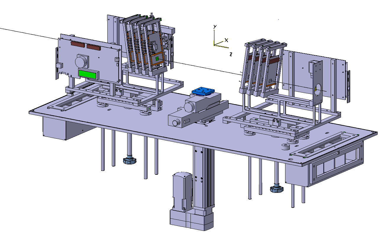
The telescope consists of two arms of four detector planes each, as illustrated in figure 1. A global right-handed coordinate frame is defined with the axis in the direction of the beam and the axis pointing upwards. This convention is adopted throughout this paper. The detector modules are 300 thick -on- pixelised silicon sensors bump-bonded to thick Timepix3 ASICs. Hence, each plane adds approximately 1 mm of silicon (, where is the radiation length) to the material budget of the telescope. The printed circuit boards that hold the sensor assemblies have a square cut-out beneath the active area of the chip and thus do not contribute to the material budget, except for an outer ring of about 0.5 mm. To improve the spatial resolution, charge sharing between pixels is maximised by placing the planes under an angle about the and with respect to the axis. For 300 thick sensors and 55 pixel pitch the optimal angle corresponds to approximately . Given the pixel pitch and a matrix size of 256256, the active area of the telescope is about 1.41.4 cm2. The positions of the telescope planes along the axis are adjustable; the telescope is operated typically with a distance of 31 mm between the planes within one arm and about 200 mm between the two arms. Cooling of the telescope planes is achieved with pre-cooled air circulating inside the telescope protective enclosure, which is also light-tight.
A DUT can be installed on a remote-controlled motion stage between the two telescope arms. The two telescope arms are mounted on rails such that the distance between the arms can be adjusted depending on the size of the DUT. The stage allows translations in and and rotations about the axis. A second stage is available downstream of the telescope which is used by DUTs larger than the available space or less demanding in terms of pointing resolution. The telescope also includes two scintillators, one upstream and one downstream of the telescope arms, which can be used to trigger the data acquisition systems of external DUTs111External devices are detectors that are not based on the Timepix3 ASIC..
Finally, the base of the telescope is mounted on a remote controlled motion stage, which allows the entire telescope to be moved in and . This allows the alignment of the telescope with respect to the beam.
3 Data Acquisition (DAQ)
The telescope silicon sensor signals are processed by Timepix3 ASICs that can be operated in different readout modes [4]. The acquisition mode used for the telescope features simultaneous measurement of the Time-of-Arrival (ToA) and Time-over-Threshold (ToT) per pixel. A pixel hit is timestamped with a Time-to-Digital converter bin size of 1.56 ns, and a timestamp range of 409.6 . The ToT measurement provides information about the amount of charge collected by the pixel. It has a range of 10 bits, with a configurable resolution that can be set via the discharge current of the preamplifier. The typical operational conditions for the telescope give a correspondence of each ToT count to a charge of about 200 e-. The capacitance of the small pixels is low and hence the noise contribution from the amplifier circuit is less than 100 e- RMS. The shot noise contribution from the sensor is negligible. Running with a nominal threshold of 1000 e- for the telescope planes ensures that there are virtually no noise hits, while allowing full detection efficiency for multi pixel clusters.
For high rate tracking performance, the chip features a so-called data-driven readout mode in which the 48 bit data packet of each pixel hit is sent off-chip immediately after ToT conversion. The chip can send out up to 80 Mhits/s over 8 serial links each running at 640 Mbit/s. To acquire the data from the ASICs a readout system called Speedy PIxel Detector Readout (SPIDR) [8, 9] is employed. The SPIDR system is specially tailored to the readout of the Timepix3 and Medipix3 chips at their maximum rate, and can be operated with both a 1 Gigabit and 10 Gigabit ethernet (GbE) interface. The 10 GbE interface is occupied when reading out a single Timepix3 chip at its maximum rate. The SPIDR version used in the telescope is based on the Xilinx Virtex 7 VC707 evaluation board and can read out two telescope planes in parallel. This is the default configuration of the readout, but to operate the whole telescope at its maximum rate each telescope plane requires a single dedicated SPIDR board.
Three data streams can be distinguished: slow control to and from the SPIDR via TCP/IP, the (full) data stream from SPIDR to computer via the User Datagram Protocol (UDP), and monitoring data from SPIDR to computer via UDP.
The two main tasks of the Virtex 7 FPGA board are the slow and fast (clock synchronisation and timing) control of the Timepix3 chips, and the packing of the data coming from the chips into UDP datagrams. Upon reception of the pixel packets, the timestamp in the packet with a range of 409.6 is extended by 16 bits, thereby increasing the range to 28.8 seconds to ease the offline reconstruction. Synchronisation of the different telescope planes is achieved via a central logic unit (TLU, Telescope Logic Unit) that provides the clock to all SPIDR systems. The TLU hardware is based on a Xilinx SP601 evaluation board and the fan out of the signal is is done with boards originally designed for a cosmic ray experiment [10]. The TLU also supplies a signal to synchronise all time counters, and a shutter signal to synchronously control the start and stop of the data flow. Each SPIDR supplies a busy signal to the TLU which is used to signal buffer overflow either in the SPIDR or its DAQ computer. If one of the systems overflows the shutter is closed by the TLU and the entire data acquisition is paused until the buffers are emptied. The SPIDR boards and the TLU receive commands from the run control software via ethernet. The run control software provides a graphical user interface for configuring the boards and ASICs and to start and stop runs. Moreover, the run control graphically displays the volume of data acquired per telescope plane. In this way problems in the data acquisition can be monitored, which occasionally occur due to radiation induced Single Event Upsets in the configuration registers of the Timepix3.
In order to simplify integration of other, non-Timepix3, detectors, the SPIDR boards feature a TDC input with 260 ps bins. The trigger signal of such a detector can then be timestamped in the clock domain of the telescope and reconstructed tracks can be linked to these triggers in the offline software. Since the telescope uses four SPIDR boards, up to four different detectors can be run simultaneously with the telescope.
4 Slow Control and Monitoring
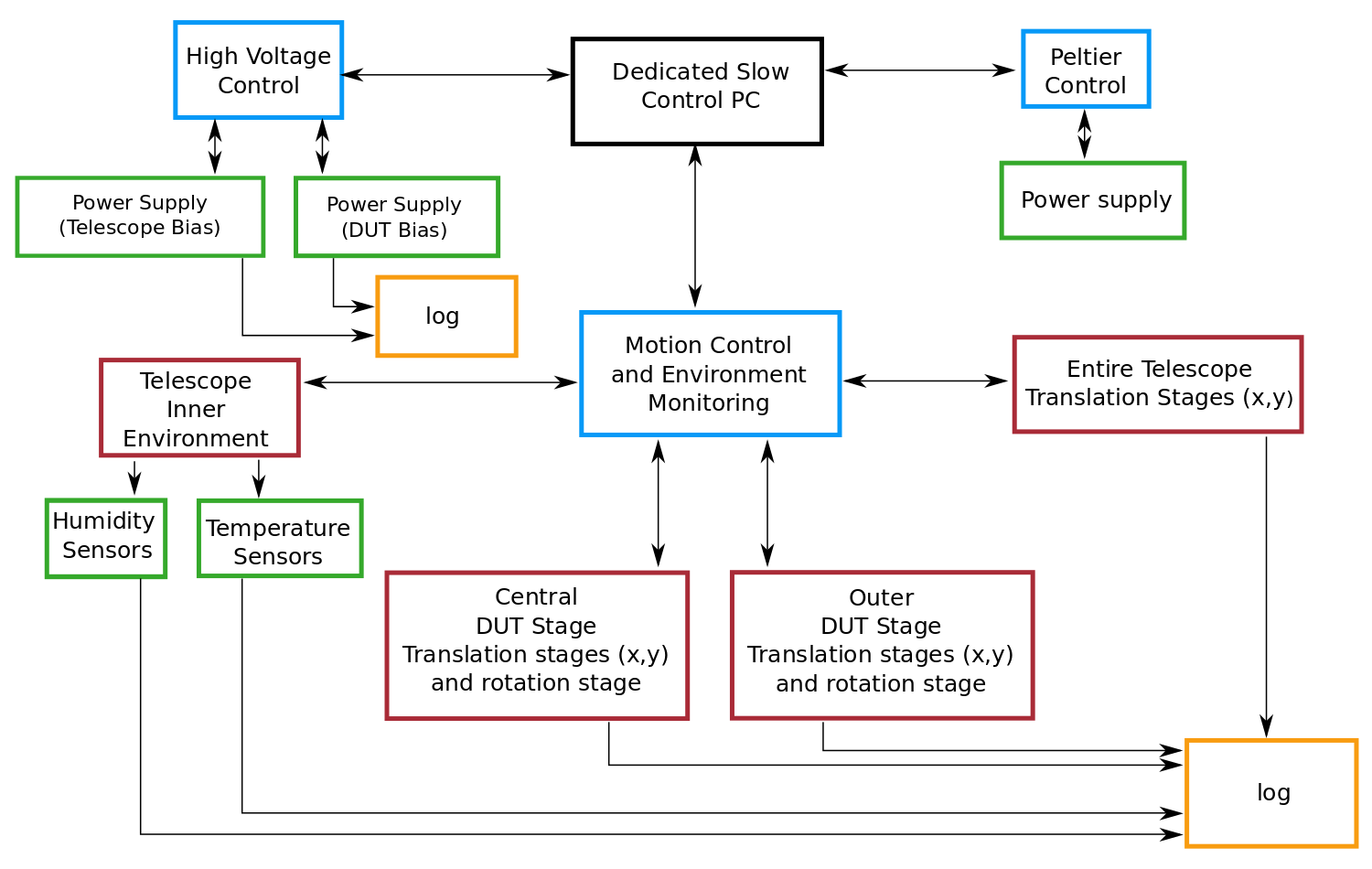
A dedicated slow control system has been developed to enable remote-control of all motion stages and power supplies. The entire telescope can be moved in and to remotely align with the beam position, or be removed from the beam path completely if required. The two DUT stages, one mounted at the centre between the two telescope arms and the other mounted outside of the main telescope enclosure, include precise remote-controlled translation and rotation stages. The translation and rotation stages, supplied by PI [11], are controlled by stepper motors and have a repeatability of 2 for translation and 50 for rotation. The vertical stages are supplied by Festo [12]. Two Keithley 2410 Source Meters [13] are used to bias independently the telescope planes and DUT. The telescope planes are usually operated with a bias tension of 150 V, which is at least 100 V above the sensor full depletion voltage. An additional power supply is also controlled remotely for a Peltier based DUT cooling system. Humidity and temperature sensors provide environmental monitoring of conditions within the telescope enclosure. The positions of all motion stages as well as the bias voltages, currents and environmental measurements are logged periodically to enable recovery of all conditions for analysis. Figure 2 summarises all elements of the slow control system.
5 Offline Reconstruction Software
A software application, “Kepler 222in honour of the German astronomer Johannes Kepler (1571-1630).”, based on the Gaudi event-processing framework [14] has been developed to analyse the telescope data and provides track fitting, alignment and charge calibration among other tasks. The application produces a ROOT file with histograms and ntuples for further user analyses.
The Gaudi framework was developed to process data taken at colliders, where there is a clear ‘event’ structure corresponding to the bunch crossing. No such structure exists in the PS and SPS secondary beams, where there is a continuous time profile during the flat top of a spill, which typically lasts about 4.5 seconds for the CERN SPS. In contrast to frame-based telescopes [3], the Timepix3 telescope data does not have an inherent event structure due to the data-driven readout described in section 3. Because the typical dataset of a run is hundreds of MBytes it is impractical to process the entire run in a single pass. The data stream is therefore divided into time slices of configurable length and each slice is processed individually. The length of the time slice is chosen to be 400 and with this setting the number of tracks that are split up into different events is negligible.
For each event, a sequence of algorithms is executed, starting by decoding the raw data files for each detector plane. The pixel packets are not received in order with respect to their timestamps. In order to ensure all hits belonging to the current event are found, it is necessary to read ahead in the file until a packet with a timestamp newer than the next-to-next event, i.e. over 800 after the start of the current event, is found.
The reconstruction of one spill ( tracks) takes approximately 70 seconds on an Intel E3 2.6 GHz processor. The large-scale processing of runs on a distributed analysis platform such as DIRAC is enabled in GANGA [15], a process management interface.
In the following sections the general structure of the telescope reconstruction software is described. The ToT to charge calibration method is described in section 5.1, followed by the time alignment in section 5.2. The clustering and tracking algorithms are detailed in section 5.3. Finally the spatial alignment is described in section 5.4.
5.1 Charge calibration
The Timepix3 ToT measurement provides information about the charge deposited in the sensor. In order to find the correspondence between ToT and charge, a calibration procedure is performed using test pulses. The ToT values are converted to charge with a surrogate function [16]. The parameters of this function are obtained for each pixel by injecting known charges via a test-pulse circuit and measuring the corresponding ToT values. The calibration has been verified using monochromatic x-rays in the Brazilian Synchrotron Light Laboratory. These two methods agree within 4% [17].
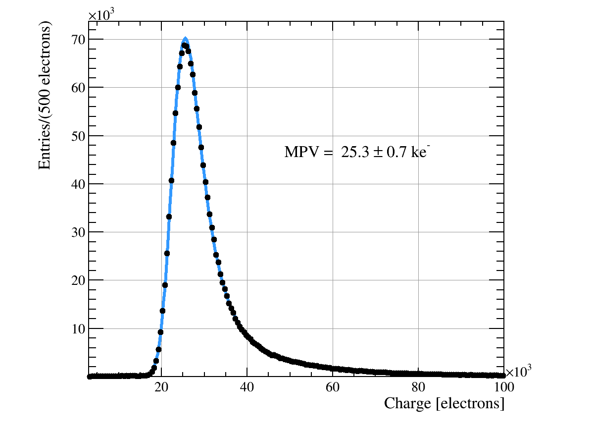
The charge collected in a typical telescope plane for clusters associated to a track is shown in figure 3. After applying the charge calibration described above, the distribution of charge deposited is well described by a Landau function convoluted with a Gaussian distribution to account for the intrinsic resolution of the charge measurement. The extracted Landau MPV (Most Probable Value) is found to be ke-, which is compatible with the expected value of a MIP crossing a 300 silicon layer.
5.2 Time alignment
There are small time offsets between the planes of the telescope due to the time of flight of the particles and non equal delays in the cables and electronics. Each plane is time aligned by minimising the variance of the cluster times (as defined in section 5.3) with a set of offsets . This is equivalent to subtracting the mean of the biased track time residuals. The offsets are measured for all runs, and found to be consistent with each other to within a spread of about , showing stability over time.
5.3 Clustering and tracking
Neighbouring pixel hits within a time window of 100 ns are grouped into a cluster. The cluster coordinates are calculated as the charge-weighted centre-of-gravity of the pixel hits constituting the cluster. The difference in the charge-weighted and ToT-weighted position resolution was studied and found to be negligible. The timestamp of the earliest hit in the cluster is used as the cluster timestamp, which mitigates the time spread due to the timewalk of hits with low charge.
The pattern recognition is based on a simple track-following technique. Track seeds are created from pairs of clusters on adjacent planes that are not yet part of a track, and differ by less than 10 ns in their timestamps. The seed tracks are extrapolated to the next plane following the beam propagation direction (downstream) and the closest cluster in time is added to the track if it is found within a temporal and spatial tolerance window. This is repeated until all planes are searched. If the candidate track comprises 8 clusters, it is accepted and a straight-line fit is performed. The track time is given by the arithmetic average of the timestamps of the clusters constituting the track. A list of the standard selection requirements used in the track reconstruction is shown in Table 1.
| Requirement | Default value | Description |
|---|---|---|
| Cluster time window | < 100 | Maximum time difference of hits |
| within the same cluster | ||
| Cluster width, in and | 3 pixels | Rejects large clusters from |
| -rays, nuclear interactions etc. | ||
| Track time window | 10 | Clusters within 10 ns window are |
| considered for the pattern recognition | ||
| Number of clusters | = 1 per plane | Rejects multi prong interaction vertices |
| in time window | ||
| Number of clusters | = 8 | Maximizes track precision |
| per track | ||
| Opening Angle | 0.01 rad | Angle that defines the reconstruction |
| window from plane to plane, | ||
| assuming straight tracks | ||
| Fit /ndof | 10 | Cut on divided by the number of |
| degrees of freedom for track quality |
5.4 Spatial alignment
The planes of the telescope are aligned using the Millipede algorithm [18]. The principal advantage of this method is the simultaneous fit of both the track states and the geometry. The algorithm is iterated several times with progressively more restrictive selections on the tracks used. A sample consisting of a fixed number of tracks, typically 8000, is reconstructed and an alignment tool executed. This alignment is then used to update the geometry constants, and the next sample of tracks can be reconstructed with reduced spatial windows and more restrictive requirements on track fit qualities. This is repeated until either all alignment tools have been executed, or the data set has been exhausted. All runs are automatically aligned using the same procedure. Alignment of DUTs that have a similar geometry as the telescope planes is also provided by the Kepler software framework, and can be integrated into the automated alignment sequence.
6 Telescope Performance
In this section the telescope performance results are presented. The most relevant parameters assessed are the track time resolution (section 6.1), the spatial resolution (section 6.2), together with its extrapolation to the track pointing resolution (section 6.3). Finally, an assessment of the high rate capabilities of the telescope is shown in section 6.5.
6.1 Time resolution
After the time alignment procedure described in section 5.2, the time resolution of the telescope can be determined. The track timestamp is calculated as the average of the associated cluster timestamps. The unbiased time resolution for a single plane is given by the standard deviation of the time residual of the clusters in one plane relative to the corresponding track, where the track time is the average time of the other seven clusters on the track. This resolution is given by the combination of the intrinsic time resolution of a single plane and the track resolution:
If the intrinsic time resolution () is the same for each plane and the errors on the time measurements are uncorrelated, the track time resolution for a telescope with planes is given by . Since the unbiased resolution is measured on a seven plane telescope, .
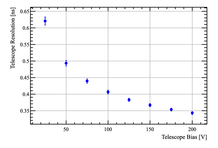
The unbiased distribution in a 22 mm2 fiducial region shows a Gaussian shape with a width of ns and from this the intrinsic time resolution is determined to be ns per plane for a bias voltage of 200 V. The difference between this result and the naïvely expected value of is due to a mixture effects such as timewalk in the chip, pixel-to-pixel variations, the spread in charge collection times in the sensor, and possibly partial correlations of the time measurements in the different planes. At 200 V bias the telescope time resolution from the combination of the eight uncorrelated measurements yields a value of 0.35 ns. Figure 4 shows the telescope time resolution as function of the applied bias tension to all planes, where this improvement is due to the lower charge collection time. Increasing the bias voltage beyond 200 V might still yield a better resolution but it was considered to pose a risk of damaging the sensors.
This resolution was cross checked by measuring the time difference with respect to two scintillators instrumented with constant fraction discriminators. The scintillator signals are timestamped with the TDCs of the SPIDR which have an average bin size of 260 ps and hence a resolution of about 75 ps. The time resolution of the scintillator system is determined to be better than 0.3 ns and this measurement confirms the track time resolution of ns.
6.2 Spatial residuals
The precision of the spatial alignment of a plane is measured in an unbiased manner by excluding it from the pattern recognition and comparing the extrapolated position of tracks with the corresponding cluster on that plane. These unbiased residuals are displayed for a typical plane in figure 5, integrated over the sensor and as a function of position. In this case the residual is shown as a function of the orthogonal position, testing for rotations around the z axis. Typically the variation across the beam spot relative to all axes is less than 0.2 , and the residual width is very stable. The unbiased residual resolution is a convolution of the pointing resolution of the telescope with the intrinsic resolution of the device.
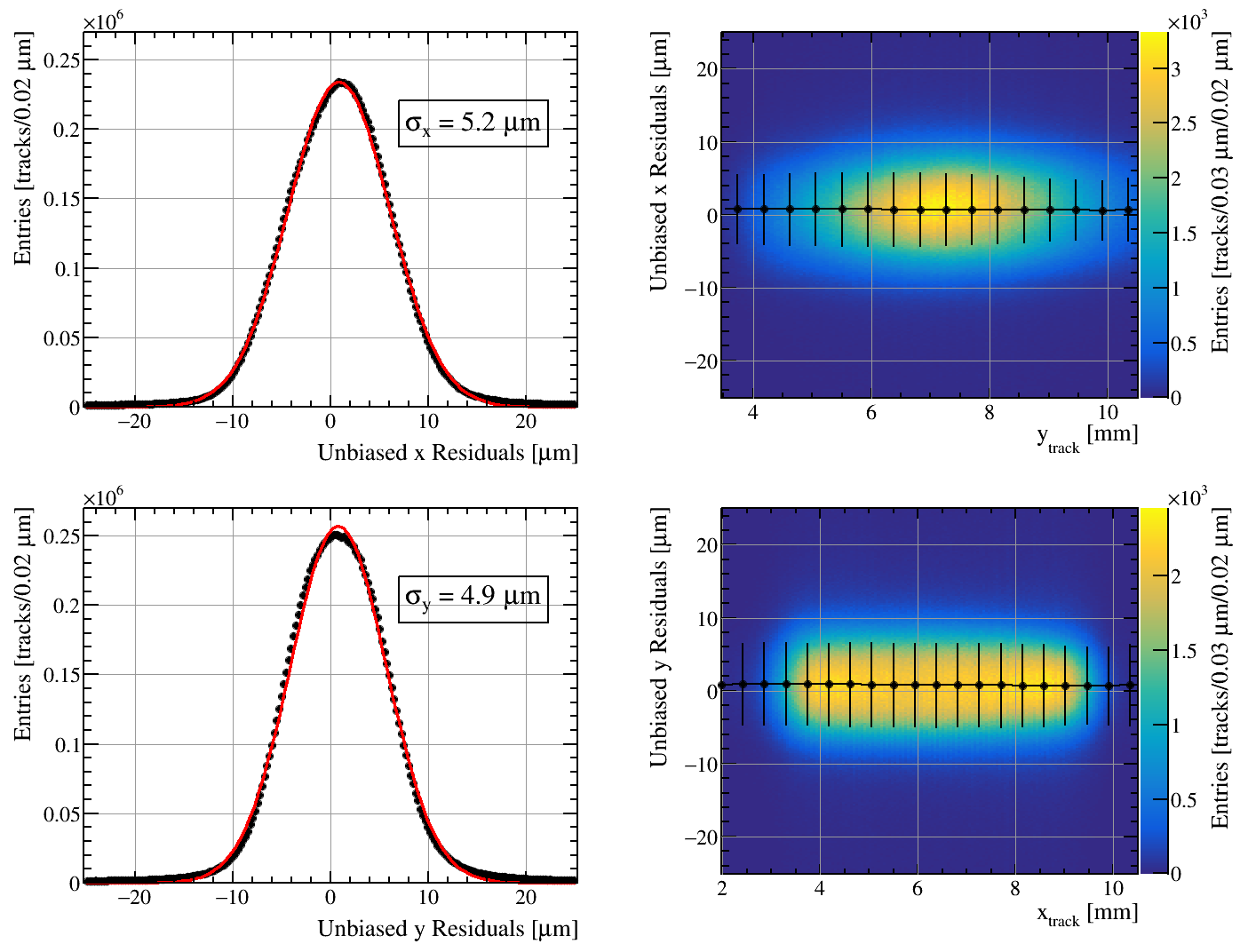
The systematic error on the resolution of each plane is estimated from the variation across the plane in both and . A spread of 3-4% (0.15 ) is obtained analysing the variations of the standard deviation of the residuals distribution.
6.3 Pointing resolution
A quantity which is of great interest for any device being tested in the telescope is the pointing resolution; the precision with which the position of each track is known when extrapolated to the DUT position. For the Timepix3 telescope this resolution is a function of the measurement precision of each plane, the spacing between the telescope planes, and the amount of material traversed by the track. In the case of high energy ( 10 GeV) hadronic beams the dominant contribution in this case is the measurement error of each plane.
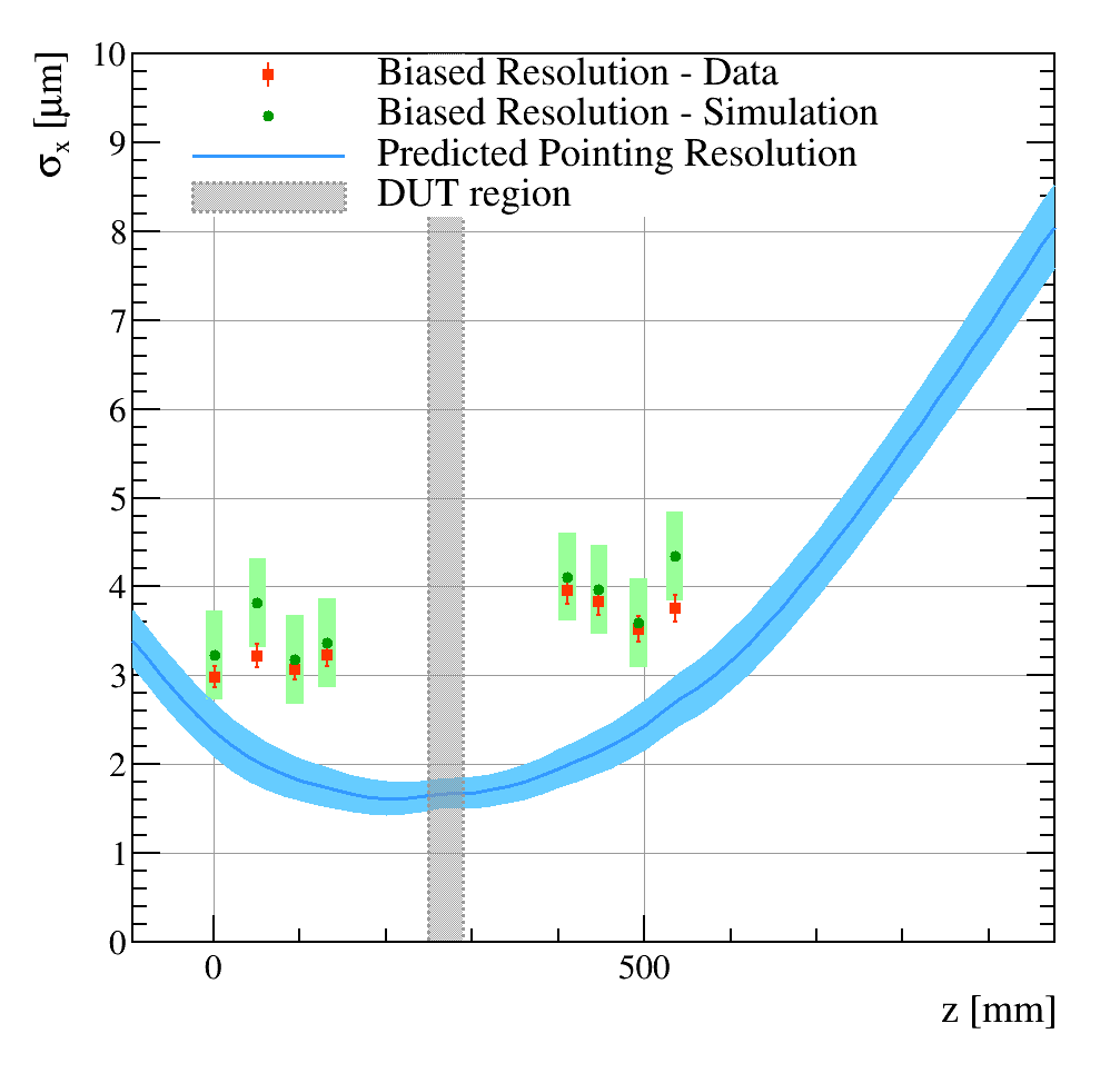
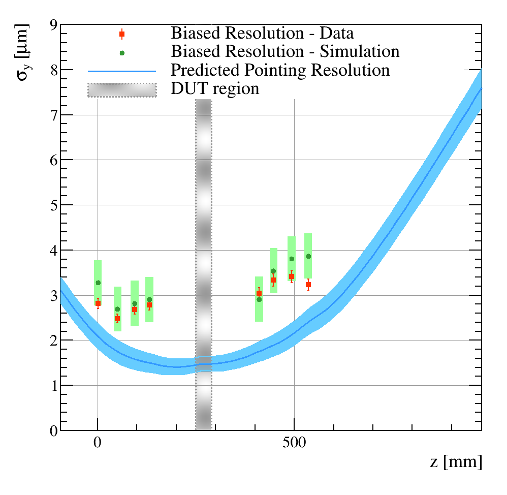
In order to determine the track-pointing resolution a simulation procedure is used. The first step is to obtain an initial estimate of the cluster resolution of each individual plane. Note that this varies plane by plane due to the slightly different thresholds used and the variations in the angle presented to the beam in both the and direction. The initial estimates are found by taking the unbiased residuals and subtracting in quadrature a reasonable first guess of the track-pointing resolution at the position of that plane. The cluster resolution values so obtained are used as inputs to a fast Monte Carlo simulation similar to the one described in Ref. [3]. The simulation gives as output the expected biased residual distributions at each plane, which are the track-cluster residuals measured at each plane for tracks which use clusters from all 8 planes. The set of biased residuals obtained from the simulation are then compared to the data, and the input errors are scaled by a single number for all planes until the best overall agreement with data is achieved. The cluster resolutions of the planes are found to be between 3.7 and 4.2 in and 2.8 and 3.4 in . The output of the simulation is used to derive the -dependent track-pointing error. A conservative estimate of the error on this quantity is derived by varying the intrinsic spatial resolution of each plane by .
The result of the study is illustrated in figure 6 for the and pointing resolution separately. There is a good agreement between the biased residuals measured in data and the ones predicted by the simulation. The predicted pointing resolution and uncertainty is shown by the blue band. The best pointing resolution is achieved at the DUT position in the centre of the telescope. Here the resolutions are and . Also at the DUT stage downstream ( mm) of the telescope a reasonable pointing precision (< 10 ) is achieved.
6.4 Track purity
The track purity is defined as the fraction of reconstructed tracks that are due to a true charged particle traversing the telescope with respect to the total number of reconstructed tracks. The precise time-stamping of each hit in the telescope allows a very clean pattern recognition. Even at the highest rates of about particles/second, the average time between tracks is 16 times larger than the tracking time window, and 160 times larger than the timestamp precision obtained in each of the planes. The use of timing measurements and the requirement to have exactly one cluster in each of the telescope planes reduce the rate of fake tracks to a negligible level. The remaining contamination from fake tracks is estimated by performing a fit to the spatial residuals of the telescope including a flat background component. This component is taken as the upper bound of the number of fake tracks and found to be below 2‰. Hence the purity of the tracks reconstructed by the telescope is above 99.8%.
6.5 High rate performance
The beam intensity at the SPS experimental area can be modified by moving collimators located upstream in the beam line. The maximum achievable sustained intensity is million tracks per spill of length 4.5 s. This limitation is imposed by the background radiation alarms that dump the beam once they are triggered. In order to operate at high rates, the configuration of the Timepix3 telescope was altered with respect to the one described in section 3. The high-rate configuration consists of six planes each read out by a dedicated SPIDR board to ensure enough throughput to run the Timepix3 ASIC at its maximum rate. During the dedicated high-rate performance runs, the beam average particle rate was gradually increased from 70k to 26M tracks per 4.5 s spill. Since the beam and the telescope are not exactly parallel, some particles will not traverse all planes and hence not result in a reconstructed track. To mitigate the impact of this effect, the high rate performance is assessed in a fiducial region which contains the highest concentration of reconstructable tracks.
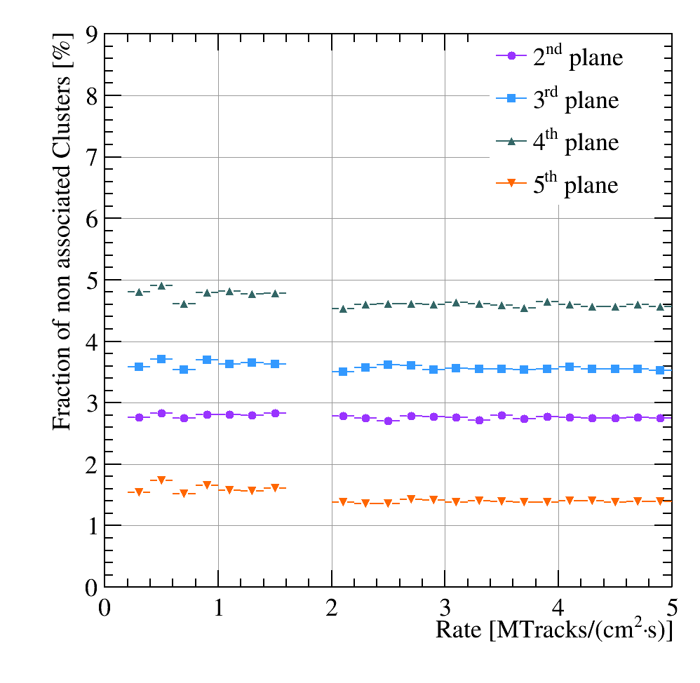
The fraction of clusters in each plane which are not associated to a track is studied in order to verify that the telescope maintains a good pattern recognition efficiency at high track rates. The dominant source of nonassociated clusters is particle interactions in the telescope material which can generate -rays, large angle scattering or vertices with multiple secondary tracks. The background rate from noise hits in the telescope is checked with runs without beam and found to be negigible. The fraction of nonassociated clusters should remain constant as the particle rate increases, as long as the pattern recognition remains efficient and there is no significant increase in the number of clusters on a particular plane. This quantity is plotted in figure 7 as a function of particle rate, where the rate is determined from the telescope track reconstruction and timestamps. Up to a rate of 5 MHz/cm2, corresponding to the maximum that the SPS can deliver, the rate of nonassociated clusters is constant, indicating that the telescope track reconstruction efficiency is not significantly degraded.
7 Summary
A high speed telescope based on the Timepix3 ASIC has been constructed. This paper presented the mechanics, data acquisition, slow controls, and performance figures. The simultaneous ToT and ToA measurements of the Timepix3 offers a fast, simple and robust pattern recognition and track reconstruction. The use of a charge-weighted clustering algorithm and a track-based alignment procedure provide residuals of the order of 4 for each telescope plane. The pointing resolution at the DUT position, in the centre of the telescope, is determined to be . A time resolution of 350 ps is achieved for reconstructed tracks traversing eight telescope planes. No deterioration of the telescope performance has been observed to a rate of 5 MHz/cm2.
8 Acknowledgements
We would like to thank the Medipix3 collaboration and especially Michael Campbell and Jerome Alozy for providing the Timepix3 assemblies for the telescope. We also express our gratitude to our colleagues in the CERN accelerator departments for the excellent performance of the PS and SPS. We gratefully acknowledge the financial support from CERN and from the national agencies: CAPES, CNPq, FAPERJ (Brazil); the Netherlands Organisation for Scientific Research (NWO); The Royal Society and the Science and Technology Facilities Council (UK).
References
- [1] R. Ballabriga, M. Campbell, and X. Llopart, Asic developments for radiation imaging applications: The medipix and timepix family, Nucl. Instrum. Meth. A878 (2018) 10
- [2] K. Akiba et al., Charged particle tracking with the Timepix ASIC, Nucl. Instrum. Meth. A661 (2011) 31, arXiv:1103.2739
- [3] K. Akiba et al., The Timepix Telescope for High Performance Particle Tracking, Nucl. Instrum. Meth. A723 (2013) 47, arXiv:1304.5175
- [4] T. Poikela et al., Timepix3: a 65k channel hybrid pixel readout chip with simultaneous toa/tot and sparse readout, Journal of Instrumentation 9 (2014), no. 05 C05013
- [5] LHCb Collaboration, LHCb VELO Upgrade Technical Design Report, Tech. Rep. CERN-LHCC-2013-021. LHCB-TDR-013, 2013
- [6] CERN, The proton synchrotron, https://home.cern/science/accelerators/proton-synchrotron
- [7] CERN, The super proton synchrotron, https://home.cern/science/accelerators/super-proton-synchrotron
- [8] J. Visser et al., SPIDR: a read-out system for Medipix3 & Timepix3, JINST 10 (2015), no. 12 C12028
- [9] B. van der Heijden et al., SPIDR, a general-purpose readout system for pixel ASICs, Journal of Instrumentation 12 (2017), no. 02 C02040
- [10] D. Cussans et al., A readout system for a cosmic ray telescope using Resistive Plate Chambers, JINST 8 (2013) C03003
- [11] P. Instrumente, Models m403.42s (translation) and m-060.2s (rotation), http://www.physikinstrumente.com
- [12] Festo, Model reference egsl-bs-55-200-5p, https://www.festo.com/
- [13] Keithley, Model 2410 smu, http://www.tek.com/keithley
- [14] M. Clemencic et al., Recent developments in the LHCb software framework Gaudi, J. Phys. Conf. Ser. 219 (2010) 042006
- [15] J. Mościcki et al., Ganga: A tool for computational-task management and easy access to grid resources, Computer Physics Communications 180 (2009), no. 11 2303
- [16] J. Jakubek et al., Pixel detectors for imaging with heavy charged particles, Nucl. Instrum. Meth. A591 (2008) 155
- [17] M. Vicente Barreto Pinto, K. Carvalho Akiba, and E. Ribeiro Polycarpo Macedo, Caracteriza o do TimePix3 e de sensores resistentes radia o para upgrade do VELO, 2016. Presented 04 Sep 2015
- [18] V. Blobel, Software alignment for tracking detectors, Nucl. Instr. Meth. A566 (2006), no. 1 5