Parametric solutions involving geometry integrated with computer-aided design

Ruben Sevilla
Zienkiewicz Centre for Computational Engineering,
College of Engineering, Swansea University, Bay Campus, SA1 8EN, Wales, UK
Sergio Zlotnik, and Antonio Huerta
Laboratori de Càlcul Numèric (LaCàN),
ETS de Ingenieros de Caminos, Canales y Puertos,
Universitat Politècnica de Catalunya, Barcelona, Spain
Abstract

The main objective of this work is to describe a general and original approach for computing an off-line solution for a set of parameters describing the geometry of the domain. That is, a solution able to include information for different geometrical parameter values and also allowing to compute readily the sensitivities. Instead of problem dependent approaches, a general framework is presented for standard engineering environments where the geometry is defined by means of NURBS. The parameters controlling the geometry are now the control points characterising the NURBS curves or surfaces. The approach proposed here, valid for 2D and 3D scenarios, allows a seamless integration with CAD preprocessors. The proper generalised decomposition (PGD), which is applied here to compute explicit geometrically parametrised solutions, circumvents the curse of dimensionality. Moreover, optimal convergence rates are shown for PGD approximations of incompressible flows.

Keywords: Geometry parametrisation; Reduced order model; Computer-aided design (CAD); Proper generalised decomposition (PGD).

1 Introduction

The current role of computational simulations in modern engineering design is limited by the complexity of the simulations that are required, particularly during the final stages of a design. The main problem is motivated by the number of configurations that need to be tested (e.g. loads, boundary conditions, material parameters and geometric configurations).

One alternative to decrease the computational complexity in this scenario is to introduce a reduced order model [27]. The main idea involves projecting the governing equations describing the full model onto a space with lower dimension that is described using a reduced order basis. Well known methods to produce reduced order basis are Krylov-based methods [16], the reduced basis method [29] and the proper orthogonal decomposition (POD) [4, 20]. More recently, the proper generalised decomposition (PGD) [8, 9] has gained popularity due to its ability to build reduced basis with no prior knowledge of the solution. The PGD starts by considering the solution not only as a function of the standard coordinates (i.e., space and time) but also of any parameter of interest (e.g. boundary conditions, external loads, material parameters). The problem involving a range of all the desired parameters can be solved at the cost of several problems of the same size as the original problem for a particular choice of the parameters. This expensive calculation, usually referred as the off-line stage, is performed only once, usually making use of high performance computing resources, to build the reduced order basis that is written as an explicit function of the coordinates (space and time) and the parameters (i.e. a computational vademecum, see [10]). Then, the on-line stage consists of just a particularisation of the solution by using, in the simplest case, an interpolation of the already computed results.

The PGD has been successfully applied to numerous multi-dimensional problems involving boundary conditions, material parameters and external loads as extra coordinates, to name a few, see [8, 9] and references therein. The application to problems involving geometrically parametrised domains is generally more challenging and the existing work is usually limited to simple geometries where the extra coordinates are scalings: the length of an interval in one-dimensional problems [11], the thickness of extruded geometries [19, 5] or problem specific parameters [17]. More recently, an approach based on an initial subdivision of the computational domain in macro-elements was proposed in [2]. This idea was extended to domains with interfaces in [34] and has been also applied to an engineering design process in [12].

In this paper, a new approach to incorporate the geometric parameters as extra coordinates in a PGD framework is proposed. The objective is to produce a general methodology that enables to obtain the solution of a particular problem when the geometry of the domain is parametrised using the NURBS boundary representation of the domain, as usually done in a computer-aided design (CAD) environment. The control points of the NURBS entities defining the boundary are considered as extra coordinates and a mapping between a reference domain and the current configuration is proposed by using a solid mechanics analogy. An explicit and separated representation of the mapping is derived and the application of the proposed methodology to Stokes flow problems is presented using examples of increasing difficulty in two and three dimensions. Contrary to the approach in [2, 34], the methodology proposed in this paper considers geometric parameters that are independent on the spatial discretisation, i.e. the control points of the NURBS entities defining the boundary representation of the domain. In addition, the technique presented here enables the solution of the multi-dimensional problem to be computed using high-order finite elements whereas the technique introduced in [2, 34] requires an affine mapping between a reference element and the macro-elements that are used to parametrise the geometry.

The structure of the remainder of the paper is as follows. Section 2 presents the problem statement using the Poisson equation on a geometrically parametrised domain and summarises the application of the PGD. Section 3 describes in detail the proposed technique to build a generalised solution assuming that a mapping between a reference configuration and the current one can be written in separated form. In Section 4, a methodology to integrate this approach in a CAD environment is presented. Considering the geometric parameters as the control points of the NURBS entities describing the boundary of the domain, the methodology to build a mapping that can be explicitly written in separated form is detailed. Finally, Section 5 presents a series of numerical examples of increasing difficulty involving the solution of Stokes flow problems in two and three dimensions.

2 Problem statement and geometrically parametrised solutions

2.1 The Poisson equation on a parametrised domain

The methodology proposed here can be directly extended to second order linear problems such as the Stokes problem that is studied in the examples. However, in order to simplify the presentation, the heat problem (Poisson) is presented in detail for a parametrised domain Ω𝝁nsdsuperscriptΩ𝝁superscriptsubscriptnsd\Omega^{\text{\boldmath$\mu$\unboldmath}}\subset\mathbb{R}^{\texttt{n}_{\texttt{sd}}} (with nsdsubscriptnsd\texttt{n}_{\texttt{sd}} number of spatial dimensions), whose boundary Ω𝝁superscriptΩ𝝁\partial\Omega^{\text{\boldmath$\mu$\unboldmath}} is characterised by a set of geometric parameters 𝝁𝓘npa𝝁𝓘superscriptsubscriptnpa\text{\boldmath$\mu$\unboldmath}\in\text{\boldmath$\mathcal{I}$\unboldmath}\subset\mathbb{R}^{\texttt{n}_{\texttt{pa}}} (with npasubscriptnpa\texttt{n}_{\texttt{pa}} number of parameters characterising the geometry) and is partitioned into Dirichlet, ΓD𝝁subscriptsuperscriptΓ𝝁𝐷\Gamma^{\text{\boldmath$\mu$\unboldmath}}_{D}, and Neumann, ΓN𝝁subscriptsuperscriptΓ𝝁𝑁\Gamma^{\text{\boldmath$\mu$\unboldmath}}_{N}, frontiers such that Ω¯𝝁=Γ¯D𝝁Γ¯N𝝁superscript¯Ω𝝁subscriptsuperscript¯Γ𝝁𝐷subscriptsuperscript¯Γ𝝁𝑁\overline{\partial\Omega}^{\text{\boldmath$\mu$\unboldmath}}=\overline{\Gamma}^{\text{\boldmath$\mu$\unboldmath}}_{D}\cup\overline{\Gamma}^{\text{\boldmath$\mu$\unboldmath}}_{N} and ΓD𝝁ΓN𝝁=subscriptsuperscriptΓ𝝁𝐷subscriptsuperscriptΓ𝝁𝑁\Gamma^{\text{\boldmath$\mu$\unboldmath}}_{D}\cap\Gamma^{\text{\boldmath$\mu$\unboldmath}}_{N}=\emptyset. Note that the set 𝓘npa𝓘superscriptsubscriptnpa\text{\boldmath$\mathcal{I}$\unboldmath}\subset\mathbb{R}^{\texttt{n}_{\texttt{pa}}}, which characterises the admissible range for parameters 𝝁𝝁\mu, can be defined as the Cartesian combination of the range for each parameter, namely, 𝓘:=1×2××npaassign𝓘subscript1subscript2subscriptsubscriptnpa\text{\boldmath$\mathcal{I}$\unboldmath}:=\mathcal{I}_{1}\times\mathcal{I}_{2}\times\dotsb\times\mathcal{I}_{\texttt{n}_{\texttt{pa}}} with μiisubscript𝜇𝑖subscript𝑖\mu_{i}\in\mathcal{I}_{i} for i=1,,npa𝑖1subscriptnpai=1,\dotsc,\texttt{n}_{\texttt{pa}}.

For each set of parameter 𝝁𝝁\mu, the objective is to determine the parametric solution u𝝁(𝒙)superscript𝑢𝝁𝒙u^{\text{\boldmath$\mu$\unboldmath}}(\text{\boldmath$x$\unboldmath}), with 𝒙Ω𝝁𝒙superscriptΩ𝝁\text{\boldmath$x$\unboldmath}\in\Omega^{\text{\boldmath$\mu$\unboldmath}}, of the boundary value problem

{(𝐊u𝝁)=sin Ω𝝁,u𝝁=uDon ΓD𝝁,𝒏(𝐊u𝝁)=ton ΓN𝝁,\left\{\begin{aligned} -\text{\boldmath$\nabla$\unboldmath}\cdot(\mathbf{K}\text{\boldmath$\nabla$\unboldmath}u^{\text{\boldmath$\mu$\unboldmath}})&=s&&\text{in $\Omega^{\text{\boldmath$\mu$\unboldmath}}$,}\\ u^{\text{\boldmath$\mu$\unboldmath}}&=u_{D}&&\text{on $\Gamma^{\text{\boldmath$\mu$\unboldmath}}_{D}$,}\\ \text{\boldmath$n$\unboldmath}\cdot(\mathbf{K}\text{\boldmath$\nabla$\unboldmath}u^{\text{\boldmath$\mu$\unboldmath}})&=t&&\text{on $\Gamma^{\text{\boldmath$\mu$\unboldmath}}_{N}$,}\end{aligned}\right. (1)

where 𝐊𝐊\mathbf{K} is the thermal conductivity (symmetric and positive definite) matrix, s𝑠s is a source term, uDsubscript𝑢𝐷u_{D} is the imposed temperature, t𝑡t is the imposed heat normal flux and 𝒏𝒏n is the outward unit normal vector. The standard variational form of the previous problem reads: find u𝝁𝒱𝝁superscript𝑢𝝁superscript𝒱𝝁u^{\text{\boldmath$\mu$\unboldmath}}\in\mathcal{V}^{\text{\boldmath$\mu$\unboldmath}} for all vΓD𝝁1𝑣subscriptsuperscript1subscriptsuperscriptΓ𝝁𝐷v\in\mathcal{H}^{1}_{\Gamma^{\text{\boldmath$\mu$\unboldmath}}_{D}} such that

a(𝝁;u𝝁,v)=(𝝁;v),𝑎𝝁superscript𝑢𝝁𝑣𝝁𝑣a(\text{\boldmath$\mu$\unboldmath};u^{\text{\boldmath$\mu$\unboldmath}},v)=\ell(\text{\boldmath$\mu$\unboldmath};v), (2a)
where the space of trial functions is 𝒱𝝁:={w1(Ω𝝁):w=uD on ΓD𝝁}assignsuperscript𝒱𝝁conditional-set𝑤superscript1superscriptΩ𝝁𝑤subscript𝑢𝐷 on subscriptsuperscriptΓ𝝁𝐷\mathcal{V}^{\text{\boldmath$\mu$\unboldmath}}:=\{w\in\mathcal{H}^{1}(\Omega^{\text{\boldmath$\mu$\unboldmath}}):w=u_{D}\text{ on }\Gamma^{\text{\boldmath$\mu$\unboldmath}}_{D}\} and its corresponding test functions space is ΓD𝝁1:={w1(Ω𝝁):w=0 on ΓD𝝁}assignsubscriptsuperscript1subscriptsuperscriptΓ𝝁𝐷conditional-set𝑤superscript1superscriptΩ𝝁𝑤0 on subscriptsuperscriptΓ𝝁𝐷\mathcal{H}^{1}_{\Gamma^{\text{\boldmath$\mu$\unboldmath}}_{D}}:=\{w\in\mathcal{H}^{1}(\Omega^{\text{\boldmath$\mu$\unboldmath}}):w=0\text{ on }\Gamma^{\text{\boldmath$\mu$\unboldmath}}_{D}\}. The parametric bilinear and linear forms a(𝝁;,)𝑎𝝁a(\text{\boldmath$\mu$\unboldmath};\cdot,\cdot) and (𝝁;)𝝁\ell(\text{\boldmath$\mu$\unboldmath};\cdot) are defined by
a(𝝁;u,v):=(v,𝐊u)Ω𝝁 and (𝝁;v):=(v,s)Ω𝝁+v,tΓN𝝁,assign𝑎𝝁𝑢𝑣subscriptbold-∇𝑣𝐊bold-∇𝑢superscriptΩ𝝁 and 𝝁𝑣assignsubscript𝑣𝑠superscriptΩ𝝁subscript𝑣𝑡subscriptsuperscriptΓ𝝁𝑁a(\text{\boldmath$\mu$\unboldmath};u,v):=\bigl{(}\text{\boldmath$\nabla$\unboldmath}v,\mathbf{K}\text{\boldmath$\nabla$\unboldmath}u\bigr{)}_{\!\Omega^{\text{\boldmath$\mu$\unboldmath}}}\text{ and }\;\ell(\text{\boldmath$\mu$\unboldmath};v):=\bigl{(}v,s\bigr{)}_{\!\Omega^{\text{\boldmath$\mu$\unboldmath}}}+\bigl{\langle}v,t\bigr{\rangle}_{\Gamma^{\text{\boldmath$\mu$\unboldmath}}_{N}}, (2b)

where

(u,v)Ω=Ωuv𝑑Ω(𝒖,𝒗)Ω=Ω𝒖𝒗𝑑Ω, and u,vΓ=Γuv𝑑Γ,formulae-sequencesubscript𝑢𝑣ΩsubscriptΩ𝑢𝑣differential-dΩformulae-sequencesubscript𝒖𝒗ΩsubscriptΩ𝒖𝒗differential-dΩ, and subscript𝑢𝑣ΓsubscriptΓ𝑢𝑣differential-dΓ\bigl{(}u,v\bigr{)}_{\!\Omega}=\int_{\Omega}u\,v\,d\Omega\text{, }\;\quad\bigl{(}\text{\boldmath$u$\unboldmath},\text{\boldmath$v$\unboldmath}\bigr{)}_{\!\Omega}=\int_{\Omega}\text{\boldmath$u$\unboldmath}\cdot\text{\boldmath$v$\unboldmath}\,d\Omega\text{, and }\;\quad\bigl{\langle}u,v\bigr{\rangle}_{\Gamma}=\int_{\Gamma}{u\,v}\,d\Gamma,

denote, respectively, the 2subscript2\mathcal{L}_{2} product of scalar/vector functions in ΩΩ\Omega and its traces over ΓΓ\Gamma.

2.2 The multi-dimensional parametric problem

There are different alternatives to obtain, for any given set of parameters 𝝁𝝁\mu, an approximation to the solution u𝝁(𝒙)superscript𝑢𝝁𝒙u^{\text{\boldmath$\mu$\unboldmath}}(\text{\boldmath$x$\unboldmath}) of problem (1). The obvious option of solving a new problem for every instance of 𝝁𝝁\mu is feasible but too costly. A standard strategy to reduce the cost is to pre-compute off-line some representative samples of the parametric family of solutions (e.g. snapshots for reduced basis methods, principal components for POD). Then, any other instance is computed on-line with a small computational overhead. Here, the PGD is preferred because the off-line phase provides an explicit description of the parametric solution, i.e. a computational vademecum see [10]. Thus, in spite of an off-line phase more involved, the on-line phase is a simple functional evaluation with a negligible computational overhead.

In practice, this can be interpreted as taking 𝝁𝝁\mu as additional independent variables (or parametric coordinates) instead of problem parameters. Hence, the unknown temperature field is not interpreted any more as a parametric solution, denoted as u𝝁superscript𝑢𝝁u^{\text{\boldmath$\mu$\unboldmath}}, but it is seen now as a function in a larger dimensional space and it is written as u(𝒙,𝝁)𝑢𝒙𝝁u(\text{\boldmath$x$\unboldmath},\text{\boldmath$\mu$\unboldmath}) with (𝒙,𝝁)Ω𝝁×𝓘𝒙𝝁superscriptΩ𝝁𝓘(\text{\boldmath$x$\unboldmath},\text{\boldmath$\mu$\unboldmath})\in\Omega^{\text{\boldmath$\mu$\unboldmath}}\times\text{\boldmath$\mathcal{I}$\unboldmath}. Consequently, formally u𝑢u lies in a tensor product space, namely, u𝒱𝝁2(1)2(2)2(npa)𝑢tensor-producttensor-producttensor-productsuperscript𝒱𝝁subscript2subscript1subscript2subscript2subscript2subscriptsubscriptnpau\in\mathcal{V}^{\text{\boldmath$\mu$\unboldmath}}\otimes\mathcal{L}_{2}(\mathcal{I}_{1})\otimes\mathcal{L}_{2}(\mathcal{I}_{2})\otimes\dotsb\otimes\mathcal{L}_{2}(\mathcal{I}_{\texttt{n}_{\texttt{pa}}}). A standard weighted residuals approach, with integrals in Ω𝝁×𝓘superscriptΩ𝝁𝓘\Omega^{\text{\boldmath$\mu$\unboldmath}}\times\text{\boldmath$\mathcal{I}$\unboldmath} and the usual integration by parts only in Ω𝝁superscriptΩ𝝁\Omega^{\text{\boldmath$\mu$\unboldmath}} produces a weak form in this multi-dimensional setup. Namely, find u𝒱𝝁2(1)2(2)2(npa)𝑢tensor-producttensor-producttensor-productsuperscript𝒱𝝁subscript2subscript1subscript2subscript2subscript2subscriptsubscriptnpau\in\mathcal{V}^{\text{\boldmath$\mu$\unboldmath}}\otimes\mathcal{L}_{2}(\mathcal{I}_{1})\otimes\mathcal{L}_{2}(\mathcal{I}_{2})\otimes\dotsb\otimes\mathcal{L}_{2}(\mathcal{I}_{\texttt{n}_{\texttt{pa}}}) such that

A(u,v)=L(v),vΓD𝝁12(I1)2(I2)2(Inpa),formulae-sequence𝐴𝑢𝑣𝐿𝑣for-all𝑣tensor-producttensor-producttensor-productsubscriptsuperscript1subscriptsuperscriptΓ𝝁𝐷subscript2subscript𝐼1subscript2subscript𝐼2subscript2subscript𝐼subscriptnpaA(u,v)=L(v),\;\forall v\in\mathcal{H}^{1}_{\Gamma^{\text{\boldmath$\mu$\unboldmath}}_{D}}\otimes\mathcal{L}_{2}(I_{1})\otimes\mathcal{L}_{2}(I_{2})\otimes\dotsb\otimes\mathcal{L}_{2}(I_{\texttt{n}_{\texttt{pa}}}), (3a)
with the following definitions of the bilinear and linear forms
A(u,v):=12npaa(𝝁;u,v)𝑑μnpa𝑑μ2𝑑μ1 and L(v):=12npa(𝝁;v)𝑑μnpa𝑑μ2𝑑μ1.assign𝐴𝑢𝑣subscriptsubscript1subscriptsubscript2subscriptsubscriptsubscriptnpa𝑎𝝁𝑢𝑣differential-dsubscript𝜇subscriptnpadifferential-dsubscript𝜇2differential-dsubscript𝜇1 and 𝐿𝑣assignsubscriptsubscript1subscriptsubscript2subscriptsubscriptsubscriptnpa𝝁𝑣differential-dsubscript𝜇subscriptnpadifferential-dsubscript𝜇2differential-dsubscript𝜇1\begin{split}A(u,v)&:=\int_{\mathcal{I}_{1}}\!\int_{\mathcal{I}_{2}}\dotsi\int_{\mathcal{I}_{\texttt{n}_{\texttt{pa}}}}a(\text{\boldmath$\mu$\unboldmath};u,v)\,d\mu_{\texttt{n}_{\texttt{pa}}}\dotsm d\mu_{2}\,d\mu_{1}\;\text{ and }\\ L(v)&:=\int_{\mathcal{I}_{1}}\!\int_{\mathcal{I}_{2}}\dotsi\int_{\mathcal{I}_{\texttt{n}_{\texttt{pa}}}}\ell(\text{\boldmath$\mu$\unboldmath};v)\,d\mu_{\texttt{n}_{\texttt{pa}}}\dotsm d\mu_{2}\,d\mu_{1}.\end{split} (3b)

Obviously, the number of dimensions of the solution domain increases with the number of parameters. To circumvent the curse of dimensionality, the PGD approach [3, 11, 8, 9] is employed here. This approach assumes a separable structure in the function that approximates u𝑢u. Note that the tensor product space 𝒱𝝁2(1)2(2)2(npa)tensor-producttensor-producttensor-productsuperscript𝒱𝝁subscript2subscript1subscript2subscript2subscript2subscriptsubscriptnpa\mathcal{V}^{\text{\boldmath$\mu$\unboldmath}}\otimes\mathcal{L}_{2}(\mathcal{I}_{1})\otimes\mathcal{L}_{2}(\mathcal{I}_{2})\otimes\dotsb\otimes\mathcal{L}_{2}(\mathcal{I}_{\texttt{n}_{\texttt{pa}}}) inherits the multi-dimensional complexity of the problem and, in principle, does not assume separability of the functions.

Moreover, the solution of (3a) requires an affine parameter dependence of the different forms. This is standard in reduced order methods and it is very well discussed in [23, 28]. More precisely, it is required that the different forms are expressed (or at least well approximated) by the sum of products of parameter-dependent functions and parameter-independent operators, for instance

a(𝝁;u,v)=q=1Q(i=1npaΘiq(μi))aq(u,v).𝑎𝝁𝑢𝑣superscriptsubscript𝑞1𝑄superscriptsubscriptproduct𝑖1subscriptnpasubscriptsuperscriptΘ𝑞𝑖subscript𝜇𝑖superscript𝑎𝑞𝑢𝑣a(\text{\boldmath$\mu$\unboldmath};u,v)=\sum_{q=1}^{Q}\biggl{(}\prod_{i=1}^{\texttt{n}_{\texttt{pa}}}\Theta^{q}_{i}(\mu_{i})\biggr{)}a^{q}(u,v).

Note that the forms aq(u,v)superscript𝑎𝑞𝑢𝑣a^{q}(u,v) do not depend on the parameters (in particular, they are integrated over domains parameter independent). In fact, finding the affine parameter dependence of (2b) is a major concern in subsequent sections and will enable to obtain a separated approximation of the solution, namely

uuPGDn=m=1nψmu(𝝁)wm(𝒙).𝑢superscriptsubscript𝑢PGD𝑛superscriptsubscript𝑚1𝑛subscriptsuperscript𝜓𝑢𝑚𝝁subscript𝑤𝑚𝒙u\approx u_{\texttt{PGD}}^{n}=\sum_{m=1}^{n}\psi^{u}_{m}(\text{\boldmath$\mu$\unboldmath})w_{m}(\text{\boldmath$x$\unboldmath}).

3 Separated spatial mapping to determine generalised solutions

If the affine parameter dependence must be enforced, it is necessary to integrate in space over domains not depending on the parameters. Note that forms a(𝝁;u,v)𝑎𝝁𝑢𝑣a(\text{\boldmath$\mu$\unboldmath};u,v) and (𝝁;v)𝝁𝑣\ell(\text{\boldmath$\mu$\unboldmath};v), see (2b), are integrated on spacial parametrised domains (domains depending on parameters 𝝁𝝁\mu). As suggested in [2, 34], a mapping 𝓜𝝁subscript𝓜𝝁\text{\boldmath$\mathcal{M}$\unboldmath}_{\text{\boldmath$\mu$\unboldmath}} is necessary (not sufficient) in order to have an affine parameter dependence. This mapping transforms a reference domain ΩΩ\Omega into the geometrically parametrised (“deformed”) domain Ω𝝁superscriptΩ𝝁\Omega^{\text{\boldmath$\mu$\unboldmath}}, namely

𝓜𝝁:Ω×𝓘:subscript𝓜𝝁Ω𝓘\displaystyle\text{\boldmath$\mathcal{M}$\unboldmath}_{\text{\boldmath$\mu$\unboldmath}}\,:\Omega\times\text{\boldmath$\mathcal{I}$\unboldmath} Ω𝝁absentsuperscriptΩ𝝁\displaystyle\longrightarrow\Omega^{\text{\boldmath$\mu$\unboldmath}} (4)
(𝑿,𝝁)𝑿𝝁\displaystyle(\text{\boldmath$X$\unboldmath},\text{\boldmath$\mu$\unboldmath}) 𝓜𝝁(𝑿,𝝁)=𝒙=𝑿+𝒅(𝑿,𝝁).absentsubscript𝓜𝝁𝑿𝝁𝒙𝑿𝒅𝑿𝝁\displaystyle\longmapsto\text{\boldmath$\mathcal{M}$\unboldmath}_{\text{\boldmath$\mu$\unboldmath}}(\text{\boldmath$X$\unboldmath},\text{\boldmath$\mu$\unboldmath})=\text{\boldmath$x$\unboldmath}=\text{\boldmath$X$\unboldmath}+\text{\boldmath$d$\unboldmath}(\text{\boldmath$X$\unboldmath},\text{\boldmath$\mu$\unboldmath}).

As classically in computational mechanics, the reference configuration ΩΩ\Omega is associated to a reference coordinate system denoted by 𝑿𝑿X, whereas the distorted domain Ω𝝁superscriptΩ𝝁\Omega^{\text{\boldmath$\mu$\unboldmath}} will be associated to the spatial description 𝒙𝒙x. Following this analogy, a displacement field 𝒅𝒅d is used to relate both coordinate systems.

The mapping 𝓜𝝁subscript𝓜𝝁\text{\boldmath$\mathcal{M}$\unboldmath}_{\text{\boldmath$\mu$\unboldmath}} can be defined in an ad hoc manner for each problem [2, 12] or by a more general strategy [2, 34], but always has to induce an affine parameter dependence of forms (2b). The introduction of this mapping allows to rewrite (2b) as integrals over the reference computational domain ΩΩ\Omega and its corresponding boundary ΩΩ\partial\Omega, partitioned into the Dirichlet, ΓDsubscriptΓ𝐷\Gamma_{D}, and Neumann, ΓNsubscriptΓ𝑁\Gamma_{N}, boundaries, all independent of parameter 𝝁𝝁\mu. Namely,

a(𝝁;u,v)=(𝐉𝝁1𝑿v,det(𝐉𝝁)𝐊𝐉𝝁1𝑿u)Ω=(𝑿v,𝐇𝝁𝑿u)Ω and (𝝁;v)=(v,det(𝐉𝝁)s)Ω+v,det(𝐉𝝁)tΓN,𝑎𝝁𝑢𝑣subscriptsuperscriptsubscript𝐉𝝁1subscriptbold-∇𝑿𝑣subscript𝐉𝝁superscriptsubscript𝐊𝐉𝝁1subscriptbold-∇𝑿𝑢Ωsubscriptsubscriptbold-∇𝑿𝑣subscript𝐇𝝁subscriptbold-∇𝑿𝑢Ω and 𝝁𝑣subscript𝑣subscript𝐉𝝁𝑠Ωsubscript𝑣subscript𝐉𝝁𝑡subscriptΓ𝑁\begin{split}a(\text{\boldmath$\mu$\unboldmath};u,v)&=\bigl{(}\mathbf{J}_{\!\text{\boldmath$\mu$\unboldmath}}^{-1}\text{\boldmath$\nabla$\unboldmath}\!\!_{\text{\boldmath$X$\unboldmath}}v,\det(\mathbf{J}_{\!\text{\boldmath$\mu$\unboldmath}})\mathbf{K}\mathbf{J}_{\!\text{\boldmath$\mu$\unboldmath}}^{-1}\text{\boldmath$\nabla$\unboldmath}\!\!_{\text{\boldmath$X$\unboldmath}}u\bigr{)}_{\!\Omega}=\bigl{(}\text{\boldmath$\nabla$\unboldmath}\!\!_{\text{\boldmath$X$\unboldmath}}v,\mathbf{H}_{\text{\boldmath$\mu$\unboldmath}}\,\text{\boldmath$\nabla$\unboldmath}\!\!_{\text{\boldmath$X$\unboldmath}}u\bigr{)}_{\!\Omega}\text{ and }\\ \ell(\text{\boldmath$\mu$\unboldmath};v)&=\bigl{(}v,\det(\mathbf{J}_{\!\text{\boldmath$\mu$\unboldmath}})\,s\bigr{)}_{\!\Omega}+\bigl{\langle}v,\det(\mathbf{J}_{\!\text{\boldmath$\mu$\unboldmath}})\,t\bigr{\rangle}_{\Gamma_{N}},\end{split} (5)

where [𝐉𝝁]ij=[xj/Xi]subscriptdelimited-[]subscript𝐉𝝁𝑖𝑗delimited-[]subscript𝑥𝑗subscript𝑋𝑖[\mathbf{J}_{\!\text{\boldmath$\mu$\unboldmath}}]_{ij}=[\partial x_{j}/\partial X_{i}] is the Jacobian matrix of the mapping 𝓜𝝁subscript𝓜𝝁\text{\boldmath$\mathcal{M}$\unboldmath}_{\text{\boldmath$\mu$\unboldmath}} and, more importantly, it is the only element in the above equations that depends upon parameters 𝝁𝝁\mu. Moreover, in order to compact the notation a new matrix 𝐇𝝁subscript𝐇𝝁\mathbf{H}_{\text{\boldmath$\mu$\unboldmath}} is introduced,

𝐇𝝁:=adj(𝐉𝝁T)𝐊adj(𝐉𝝁)det(𝐉𝝁),assignsubscript𝐇𝝁adjsuperscriptsubscript𝐉𝝁𝑇𝐊adjsubscript𝐉𝝁subscript𝐉𝝁\mathbf{H}_{\text{\boldmath$\mu$\unboldmath}}:=\frac{\operatorname{adj}(\mathbf{J}_{\!\text{\boldmath$\mu$\unboldmath}}^{T})\,\mathbf{K}\,\operatorname{adj}(\mathbf{J}_{\!\text{\boldmath$\mu$\unboldmath}})}{\det(\mathbf{J}_{\!\text{\boldmath$\mu$\unboldmath}})}, (6)

where the definition of the adjoint operator, adj(𝑨)=det(𝑨)𝑨1adj𝑨𝑨superscript𝑨1\operatorname{adj}(\text{\boldmath$A$\unboldmath})=\det(\text{\boldmath$A$\unboldmath})\,\text{\boldmath$A$\unboldmath}^{-1}, has been used.

Note that even for ad hoc [2] or a piecewise linear [2, 34] mappings, the affine parameter dependence of the different forms in (5) must be now determined.

Remark 1 (Mapping for the Stokes problem).

Despite being more cumbersome, the same rationale can be applied for the Stokes problem without any extra conceptual challenge. The bilinear viscosity form is reproduced here for illustration purposes

a(𝝁;𝒖,𝒗)=(𝐯,𝐂¯¯:𝐮)Ω𝝁=(𝑿𝒗,𝐂¯^¯𝝁:𝑿𝒖)Ω,a(\text{\boldmath$\mu$\unboldmath};\text{\boldmath$u$\unboldmath},\text{\boldmath$v$\unboldmath})=\bigl{(}\text{\boldmath$\nabla$\unboldmath}\text{\boldmath$v$\unboldmath},\underline{\underline{\mathbf{C}}}:\text{\boldmath$\nabla$\unboldmath}\text{\boldmath$u$\unboldmath}\bigr{)}_{\!\Omega^{\text{\boldmath$\mu$\unboldmath}}}=\bigl{(}\text{\boldmath$\nabla$\unboldmath}\!\!_{\text{\boldmath$X$\unboldmath}}\text{\boldmath$v$\unboldmath},\underline{\underline{\mathbf{\hat{C}}}}^{\text{\boldmath$\mu$\unboldmath}}:\text{\boldmath$\nabla$\unboldmath}\!\!_{\text{\boldmath$X$\unboldmath}}\text{\boldmath$u$\unboldmath}\bigr{)}_{\!\Omega},

where Cijkl=νδikδjlsubscriptC𝑖𝑗𝑘𝑙𝜈subscript𝛿𝑖𝑘subscript𝛿𝑗𝑙\text{C}_{ijkl}=\nu\,\delta_{ik}\,\delta_{jl}, C^ijkl𝛍=νdet(𝐉𝛍)δik[𝐉𝛍𝐓]js[𝐉𝛍𝟏]slsuperscriptsubscript^C𝑖𝑗𝑘𝑙𝛍𝜈subscript𝐉𝛍subscript𝛿𝑖𝑘subscriptdelimited-[]superscriptsubscript𝐉𝛍𝐓𝑗𝑠subscriptdelimited-[]superscriptsubscript𝐉𝛍1𝑠𝑙\hat{\text{C}}_{ijkl}^{\text{\boldmath$\mu$\unboldmath}}=\nu\det(\mathbf{J_{\text{\boldmath$\mu$\unboldmath}}})\,\delta_{ik}\,[\mathbf{J_{\text{\boldmath$\mu$\unboldmath}}^{-T}}]_{js}\,[\mathbf{J_{\text{\boldmath$\mu$\unboldmath}}^{-1}}]_{sl} and ν>0𝜈0\nu>0 is the kinematic viscosity. Note that [𝐀]ijsubscriptdelimited-[]𝐀𝑖𝑗[\mathbf{A}]_{ij} denotes the component ij𝑖𝑗ij of a matrix 𝐀𝐀\mathbf{A}.

3.1 Separated displacements

The methodology proposed here allows to obtain an affine parameter dependence (namely, a separable expression for 𝐇𝝁subscript𝐇𝝁\mathbf{H}_{\text{\boldmath$\mu$\unboldmath}}) quasi-analytically if the mapping can be written (or at least, well approximated) with a separated representation, that is as a sum of separated terms, namely

𝓜𝝁(𝑿,𝝁)=𝑿+m=1Nψm(𝝁)𝒅m(𝑿),subscript𝓜𝝁𝑿𝝁𝑿superscriptsubscript𝑚1𝑁subscript𝜓𝑚𝝁superscript𝒅𝑚𝑿\text{\boldmath$\mathcal{M}$\unboldmath}_{\text{\boldmath$\mu$\unboldmath}}(\text{\boldmath$X$\unboldmath},\text{\boldmath$\mu$\unboldmath})=\text{\boldmath$X$\unboldmath}+\sum_{m=1}^{N}\psi_{m}(\text{\boldmath$\mu$\unboldmath})\;\text{\boldmath$d$\unboldmath}^{m}(\text{\boldmath$X$\unboldmath}), (7)

which induces a separated Jacobian matrix

𝐉𝝁(𝑿,𝝁)=𝒙𝑿(𝑿,𝝁)=𝐈nsd+m=1Nψm𝐀m,subscript𝐉𝝁𝑿𝝁𝒙𝑿𝑿𝝁subscript𝐈subscriptnsdsuperscriptsubscript𝑚1𝑁subscript𝜓𝑚subscript𝐀𝑚\mathbf{J}_{\!\text{\boldmath$\mu$\unboldmath}}(\text{\boldmath$X$\unboldmath},\text{\boldmath$\mu$\unboldmath})=\frac{\partial\text{\boldmath$x$\unboldmath}}{\partial\text{\boldmath$X$\unboldmath}}(\text{\boldmath$X$\unboldmath},\text{\boldmath$\mu$\unboldmath})=\mathbf{I}_{\texttt{n}_{\texttt{sd}}}+\sum_{m=1}^{N}\psi_{m}\,\mathbf{A}_{m}, (8)

where 𝐀m:=[𝒅m/𝑿]assignsubscript𝐀𝑚delimited-[]superscript𝒅𝑚𝑿\mathbf{A}_{m}:=[\partial\text{\boldmath$d$\unboldmath}^{m}/\partial\text{\boldmath$X$\unboldmath}] for m=1,,N𝑚1𝑁m=1,\dotsc,N.

3.2 Affine parameter dependence

The affine parameter dependence of a(𝝁;u,v)𝑎𝝁𝑢𝑣a(\text{\boldmath$\mu$\unboldmath};u,v) as defined in (5), is in practice determined by obtaining a separated expression of 𝐇𝝁subscript𝐇𝝁\mathbf{H}_{\text{\boldmath$\mu$\unboldmath}}. In order to obtain a separated expression for matrix 𝐇𝝁subscript𝐇𝝁\mathbf{H}_{\text{\boldmath$\mu$\unboldmath}}, both adj(𝐉𝝁)adjsubscript𝐉𝝁\operatorname{adj}(\mathbf{J}_{\!\text{\boldmath$\mu$\unboldmath}}) and det(𝐉𝝁)subscript𝐉𝝁\det(\mathbf{J}_{\!\text{\boldmath$\mu$\unboldmath}}) are analytically separated. Then, the Higher-Order PGD-Projection proposed in [22] is used to obtain a compact separation for 𝐇𝝁subscript𝐇𝝁\mathbf{H}_{\text{\boldmath$\mu$\unboldmath}}.

The separated representation for the determinant, det(𝐉𝝁)subscript𝐉𝝁\det(\mathbf{J}_{\!\text{\boldmath$\mu$\unboldmath}}), can be obtained using Leibniz formula from equation (8), whereas for adj(𝐉𝝁)adjsubscript𝐉𝝁\operatorname{adj}(\mathbf{J}_{\!\text{\boldmath$\mu$\unboldmath}}), the Leverrier’s algorithm [15] is employed. This method is a consequence of the Cayley-Hamilton theorem [6, 18] and the Newton’s identities [21]. It enables to express the adjoint of a matrix 𝐀n×n𝐀superscript𝑛𝑛\mathbf{A}\in\mathbb{R}^{n\times n} in terms of its trace and its powers, namely

adj(𝐀)=s=0n1𝐀sk1,k2,,kn1l=1n1(1)kl+1lklkl!tr(𝐀l)kl\operatorname{adj}(\mathbf{A})=\sum_{s=0}^{n-1}\mathbf{A}^{s}\sum_{k_{1},k_{2},\dotsc,k_{n-1}}\prod_{l=1}^{n-1}\frac{(-1)^{k_{l}+1}}{l^{k_{l}}k_{l}!}\operatorname{tr}(\mathbf{A}^{l})^{k_{l}} (9)

where kl0subscript𝑘𝑙subscript0k_{l}\in\mathbb{N}_{0} and s+l=1n1lkl=n1𝑠superscriptsubscript𝑙1𝑛1𝑙subscript𝑘𝑙𝑛1s+\sum_{l=1}^{n-1}lk_{l}=n-1. In practice, the two cases of interest are 2D (n=2𝑛2n=2) and 3D (n=3𝑛3n=3) problems, which are detailed next.

3.3 Two-dimensional approach

In 2D the Jacobian 𝐉𝝁subscript𝐉𝝁\mathbf{J}_{\!\text{\boldmath$\mu$\unboldmath}} is a 2×2222\times 2 matrix. From (8), the separated expression for its determinant is

det(𝐉𝝁)=(1+m=1Nψm(𝝁)[𝐀m]11)(1+m=1Nψm(𝝁)[𝐀m]22)(m=1Nψm(𝝁)[𝐀m]21)(m=1Nψm(𝝁)[𝐀m]12),subscript𝐉𝝁1superscriptsubscript𝑚1𝑁subscript𝜓𝑚𝝁subscriptdelimited-[]subscript𝐀𝑚111superscriptsubscript𝑚1𝑁subscript𝜓𝑚𝝁subscriptdelimited-[]subscript𝐀𝑚22superscriptsubscript𝑚1𝑁subscript𝜓𝑚𝝁subscriptdelimited-[]subscript𝐀𝑚21superscriptsubscript𝑚1𝑁subscript𝜓𝑚𝝁subscriptdelimited-[]subscript𝐀𝑚12\det(\mathbf{J}_{\!\text{\boldmath$\mu$\unboldmath}})=\Bigl{(}1+\sum_{m=1}^{N}\psi_{m}(\text{\boldmath$\mu$\unboldmath})\bigl{[}\mathbf{A}_{m}\bigr{]}_{11}\Bigr{)}\Bigl{(}1+\sum_{m=1}^{N}\psi_{m}(\text{\boldmath$\mu$\unboldmath})\bigl{[}\mathbf{A}_{m}\bigr{]}_{22}\Bigr{)}\\ -\Bigl{(}\sum_{m=1}^{N}\psi_{m}(\text{\boldmath$\mu$\unboldmath})\bigl{[}\mathbf{A}_{m}\bigr{]}_{21}\Bigr{)}\Bigl{(}\sum_{m=1}^{N}\psi_{m}(\text{\boldmath$\mu$\unboldmath})\bigl{[}\mathbf{A}_{m}\bigr{]}_{12}\Bigr{)}, (10)

again [𝐀]ijsubscriptdelimited-[]𝐀𝑖𝑗[\mathbf{A}]_{ij} denotes the component ij𝑖𝑗ij of the matrix 𝐀𝐀\mathbf{A}.

To obtain the expression for the adjoint requires to particularise (9), namely

adj(𝐀)=tr(𝐀)𝐈2𝐀,adj𝐀tr𝐀subscript𝐈2𝐀\operatorname{adj}(\mathbf{A})=\operatorname{tr}(\mathbf{A})\mathbf{I}_{2}-\mathbf{A},

which is a linear mapping because the trace is also linear. Thus, the Jacobian in separated form as presented in (8) can be written as

adj(𝐉𝝁)=𝐈2+m=1Nψmadj([𝒅m/𝑿])=𝐈2+m=1Nψmadj(𝐀m).adjsubscript𝐉𝝁subscript𝐈2superscriptsubscript𝑚1𝑁subscript𝜓𝑚adjdelimited-[]superscript𝒅𝑚𝑿subscript𝐈2superscriptsubscript𝑚1𝑁subscript𝜓𝑚adjsubscript𝐀𝑚\operatorname{adj}(\mathbf{J}_{\!\text{\boldmath$\mu$\unboldmath}})=\mathbf{I}_{2}+\sum_{m=1}^{N}\psi_{m}\,\operatorname{adj}\bigl{(}[\partial\text{\boldmath$d$\unboldmath}^{m}/\partial\text{\boldmath$X$\unboldmath}]\bigr{)}=\mathbf{I}_{2}+\sum_{m=1}^{N}\psi_{m}\,\operatorname{adj}(\mathbf{A}_{m}). (11)

Consequently, recalling that adj(𝐀T)=adj(𝐀)T\operatorname{adj}(\mathbf{A}^{T})=\operatorname{adj}(\mathbf{A})^{T}, the matrix 𝐇𝝁subscript𝐇𝝁\mathbf{H}_{\text{\boldmath$\mu$\unboldmath}} in (6) can be rewritten as

det(𝐉𝝁)𝐇𝝁=𝐊+m=1Nψm𝐊adj(𝐀m)+m=1Nψm[𝐊adj(𝐀m)]T+m=1Nl=1Nψmψladj(𝐀m)T𝐊adj(𝐀l).\det(\mathbf{J}_{\!\text{\boldmath$\mu$\unboldmath}})\;\mathbf{H}_{\text{\boldmath$\mu$\unboldmath}}=\mathbf{K}+\sum_{m=1}^{N}\psi_{m}\,\mathbf{K}\,\operatorname{adj}(\mathbf{A}_{m})+\sum_{m=1}^{N}\psi_{m}\bigl{[}\mathbf{K}\,\operatorname{adj}(\mathbf{A}_{m})\bigr{]}^{T}\\ +\sum_{m=1}^{N}\sum_{l=1}^{N}\psi_{m}\psi_{l}\,\operatorname{adj}(\mathbf{A}_{m})^{T}\,\mathbf{K}\,\operatorname{adj}(\mathbf{A}_{l}).

The separated expression of 𝐇𝝁subscript𝐇𝝁\mathbf{H}_{\text{\boldmath$\mu$\unboldmath}} is efficiently obtained with a numerical Higher-Order PGD-Projection [22].

3.4 Three-dimensional approach

Following the previous rationale, in 3D the Jacobian 𝐉𝝁subscript𝐉𝝁\mathbf{J}_{\!\text{\boldmath$\mu$\unboldmath}} is a 3×3333\times 3 matrix. The separated expression for the determinant, det(𝐉𝝁)subscript𝐉𝝁\det(\mathbf{J}_{\!\text{\boldmath$\mu$\unboldmath}}), is obtained using Leibniz formula as

det(𝐉𝝁)=σ𝒮3sgn(σ)i=13(1+m=1Nψm(𝝁)[𝐀m]iσ(i)),subscript𝐉𝝁subscript𝜎subscript𝒮3sgn𝜎superscriptsubscriptproduct𝑖131superscriptsubscript𝑚1𝑁subscript𝜓𝑚𝝁subscriptdelimited-[]subscript𝐀𝑚𝑖𝜎𝑖\det(\mathbf{J}_{\!\text{\boldmath$\mu$\unboldmath}})=\sum_{\sigma\in\mathcal{S}_{3}}\operatorname{sgn}(\sigma)\prod_{i=1}^{3}\Bigl{(}1{+}\sum_{m=1}^{N}\psi_{m}(\text{\boldmath$\mu$\unboldmath})\bigl{[}\mathbf{A}_{m}\bigr{]}_{i\sigma(i)}\Bigr{)}, (12)

where 𝒮3subscript𝒮3\mathcal{S}_{3} is the set of the six permutations of the integers {1,2,3}123\{1,2,3\}, where the element in position i𝑖i after the reordering σ𝜎\sigma is denoted σ(i)𝜎𝑖\sigma(i), and sgn(σ)sgn𝜎\operatorname{sgn}(\sigma) denotes the signature of σ𝜎\sigma (i.e. +11+1 for even σ𝜎\sigma and 11-1 for odd σ𝜎\sigma). Note that such a separation will induce sums of order N3superscript𝑁3N^{3}.

The adjoint of the Jacobian is also separated by means of particularising (9) to 3D,

adj(𝐀)=12[(tr(𝐀))2tr(𝐀2)]𝐈3tr(𝐀)𝐀+𝐀2,adj𝐀12delimited-[]superscripttr𝐀2trsuperscript𝐀2subscript𝐈3tr𝐀𝐀superscript𝐀2\operatorname{adj}(\mathbf{A})=\tfrac{1}{2}\bigl{[}\bigl{(}\operatorname{tr}(\mathbf{A})\bigr{)}^{2}-\operatorname{tr}(\mathbf{A}^{2})\bigr{]}\mathbf{I}_{3}-\operatorname{tr}(\mathbf{A})\mathbf{A}+\mathbf{A}^{2},

and given the separation of the Jacobian in (8) implies

adj(𝐉𝝁)=𝐈3+m=1Nψm[tr(𝐀m)𝐈3𝐀m]+m=1Nl=1Nψmψl[12(tr(𝐀m)tr(𝐀l)tr(𝐀m𝐀l))𝐈3tr(𝐀m)𝐀l+𝐀m𝐀l].adjsubscript𝐉𝝁subscript𝐈3superscriptsubscript𝑚1𝑁subscript𝜓𝑚delimited-[]trsubscript𝐀𝑚subscript𝐈3subscript𝐀𝑚superscriptsubscript𝑚1𝑁superscriptsubscript𝑙1𝑁subscript𝜓𝑚subscript𝜓𝑙delimited-[]12trsubscript𝐀𝑚trsubscript𝐀𝑙trsubscript𝐀𝑚subscript𝐀𝑙subscript𝐈3trsubscript𝐀𝑚subscript𝐀𝑙subscript𝐀𝑚subscript𝐀𝑙\operatorname{adj}(\mathbf{J}_{\!\text{\boldmath$\mu$\unboldmath}})=\mathbf{I}_{3}+\sum_{m=1}^{N}\psi_{m}\bigl{[}\operatorname{tr}(\mathbf{A}_{m})\mathbf{I}_{3}-\mathbf{A}_{m}\bigr{]}\\ +\sum_{m=1}^{N}\sum_{l=1}^{N}\psi_{m}\psi_{l}\bigl{[}\frac{1}{2}\bigl{(}\operatorname{tr}(\mathbf{A}_{m})\operatorname{tr}(\mathbf{A}_{l})-\operatorname{tr}(\mathbf{A}_{m}\mathbf{A}_{l})\bigr{)}\mathbf{I}_{3}-\operatorname{tr}(\mathbf{A}_{m})\mathbf{A}_{l}+\mathbf{A}_{m}\mathbf{A}_{l}\bigr{]}. (13)

As done in 2D, once the adjoint is separated, from (6), a separated expression for det(𝐉𝝁)𝐇𝝁=adj(𝐉𝝁T)𝐊adj(𝐉𝝁)subscript𝐉𝝁subscript𝐇𝝁adjsuperscriptsubscript𝐉𝝁𝑇𝐊adjsubscript𝐉𝝁\det(\mathbf{J}_{\!\text{\boldmath$\mu$\unboldmath}})\mathbf{H}_{\text{\boldmath$\mu$\unboldmath}}=\operatorname{adj}(\mathbf{J}_{\!\text{\boldmath$\mu$\unboldmath}}^{T})\,\mathbf{K}\,\operatorname{adj}(\mathbf{J}_{\!\text{\boldmath$\mu$\unboldmath}}) can be computed. In this case, it consists of N4superscript𝑁4N^{4} terms. As previously noted for 2D, the separated expression of 𝐇𝝁subscript𝐇𝝁\mathbf{H}_{\text{\boldmath$\mu$\unboldmath}} is obtained with the Higher-Order PGD-Projection described next.

3.5 The Higher-Order PGD-Projection

Finally, to obtain a separated approximation of 𝐇𝝁subscript𝐇𝝁\mathbf{H}_{\text{\boldmath$\mu$\unboldmath}}, namely

𝐇𝝁𝐇𝝁sep(𝒙,𝝁)=m=1NHψm𝐇(𝝁)𝐀m𝐇(𝑿),subscript𝐇𝝁superscriptsubscript𝐇𝝁sep𝒙𝝁superscriptsubscript𝑚1subscript𝑁𝐻subscriptsuperscript𝜓𝐇𝑚𝝁subscriptsuperscript𝐀𝐇𝑚𝑿\mathbf{H}_{\text{\boldmath$\mu$\unboldmath}}\approx\mathbf{H}_{\text{\boldmath$\mu$\unboldmath}}^{\texttt{sep}}(\text{\boldmath$x$\unboldmath},\text{\boldmath$\mu$\unboldmath})=\sum_{m=1}^{N_{H}}\psi^{\mathbf{H}}_{m}(\text{\boldmath$\mu$\unboldmath})\,\mathbf{A}^{\mathbf{H}}_{m}(\text{\boldmath$X$\unboldmath}),

equation (6) has to be solved. This is done by means of the Higher-Order PGD-Projection [22], which in practice obtains the separated approximation with an 2subscript2\mathcal{L}_{2} projection, say

(𝒗,𝐇𝝁sep)Ω×𝓘=(𝒗,adj(𝐉𝝁T)𝐊adj(𝐉𝝁)/det(𝐉𝝁))Ω×𝓘subscript𝒗subscriptsuperscript𝐇sep𝝁Ω𝓘subscript𝒗adjsuperscriptsubscript𝐉𝝁𝑇𝐊adjsubscript𝐉𝝁subscript𝐉𝝁Ω𝓘\bigl{(}\text{\boldmath$v$\unboldmath},\mathbf{H}^{\texttt{sep}}_{\text{\boldmath$\mu$\unboldmath}}\bigr{)}_{\Omega\times\text{\boldmath$\mathcal{I}$\unboldmath}}=\bigl{(}\text{\boldmath$v$\unboldmath},\operatorname{adj}(\mathbf{J}_{\!\text{\boldmath$\mu$\unboldmath}}^{T})\,\mathbf{K}\,\operatorname{adj}(\mathbf{J}_{\!\text{\boldmath$\mu$\unboldmath}})/\det(\mathbf{J}_{\!\text{\boldmath$\mu$\unboldmath}})\bigr{)}_{\Omega\times\text{\boldmath$\mathcal{I}$\unboldmath}}

for all 𝒗𝒗v in a suitable space. In practice, the PGD strategy is implemented. Thus, a greedy approach is used. For computational efficiency, it is critical to use the exact separated expressions for the determinant, see (10) and (12), and the adjoint of the Jacobian, see (11) and (13). In practice, each mode of 𝐇𝝁sepsuperscriptsubscript𝐇𝝁sep\mathbf{H}_{\text{\boldmath$\mu$\unboldmath}}^{\texttt{sep}} is obtained by solving

(𝒗,det(𝐉𝝁)ψn𝐇𝐀n𝐇)Ω×𝓘=(𝒗,adj(𝐉𝝁T)𝐊adj(𝐉𝝁))Ω×𝓘(𝒗,det(𝐉𝝁)m=1n1ψm𝐇𝐀m𝐇)Ω×𝓘,subscript𝒗subscript𝐉𝝁subscriptsuperscript𝜓𝐇𝑛subscriptsuperscript𝐀𝐇𝑛Ω𝓘subscript𝒗adjsuperscriptsubscript𝐉𝝁𝑇𝐊adjsubscript𝐉𝝁Ω𝓘subscript𝒗subscript𝐉𝝁superscriptsubscript𝑚1𝑛1subscriptsuperscript𝜓𝐇𝑚subscriptsuperscript𝐀𝐇𝑚Ω𝓘\bigl{(}\text{\boldmath$v$\unboldmath},\det(\mathbf{J}_{\!\text{\boldmath$\mu$\unboldmath}})\,\psi^{\mathbf{H}}_{n}\,\mathbf{A}^{\mathbf{H}}_{n}\bigr{)}_{\Omega\times\text{\boldmath$\mathcal{I}$\unboldmath}}=\bigl{(}\text{\boldmath$v$\unboldmath},\operatorname{adj}(\mathbf{J}_{\!\text{\boldmath$\mu$\unboldmath}}^{T})\,\mathbf{K}\,\operatorname{adj}(\mathbf{J}_{\!\text{\boldmath$\mu$\unboldmath}})\bigr{)}_{\Omega\times\text{\boldmath$\mathcal{I}$\unboldmath}}\\ -\bigl{(}\text{\boldmath$v$\unboldmath},\det(\mathbf{J}_{\!\text{\boldmath$\mu$\unboldmath}})\,\sum_{m=1}^{n-1}\psi^{\mathbf{H}}_{m}\,\mathbf{A}^{\mathbf{H}}_{m}\bigr{)}_{\Omega\times\text{\boldmath$\mathcal{I}$\unboldmath}}, (14)

where now, as usual in PGD, 𝒗𝒗v lives in the tangent space of the mode. Note that the Higher-Order PGD-Projection allows many parameters without any prior knowledge, is computationally efficient, and the precision of this approximation (i.e. the total number of terms NHsubscript𝑁𝐻N_{H}) can be controlled by the user.

4 Integration within a CAD environment

In this section a procedure to integrate the methodology described in the previous section within a CAD environment is proposed. To simplify the presentation, the two dimensional case is presented here and the details for the extension to three dimensional domains are given in A.

The boundary of the parametrised domain, Ω𝝁superscriptΩ𝝁\partial\Omega^{\text{\boldmath$\mu$\unboldmath}}, is assumed to be described by a set of NURBS curves {𝑪j𝝁}j=1,,Msubscriptsuperscriptsubscript𝑪𝑗𝝁𝑗1𝑀\{\text{\boldmath$C$\unboldmath}_{\!j}^{\text{\boldmath$\mu$\unboldmath}}\}_{j=1,\dotsc,M}, being M𝑀M the total number of curves, namely

Ω𝝁=j=1M𝑪j𝝁([0,1]).superscriptΩ𝝁superscriptsubscript𝑗1𝑀superscriptsubscript𝑪𝑗𝝁01\partial\Omega^{\text{\boldmath$\mu$\unboldmath}}=\bigcup_{j=1}^{M}\text{\boldmath$C$\unboldmath}_{\!j}^{\text{\boldmath$\mu$\unboldmath}}([0,1]).

Next, the necessary concepts about NURBS curves are briefly recalled and the proposed strategy to build a geometric mapping 𝓜𝝁subscript𝓜𝝁\text{\boldmath$\mathcal{M}$\unboldmath}_{\text{\boldmath$\mu$\unboldmath}} that can be written in the separated form (7) is presented in detail.

4.1 NURBS curves

A q𝑞qth-degree non-uniform rational B-spline (NURBS) curve is a piecewise rational function defined in parametric form as

𝑪(λ)=i=0ncp𝑩iRi(λ)λ[0,1]formulae-sequencesubscript𝑪absent𝜆superscriptsubscript𝑖0subscriptncpsubscript𝑩𝑖subscript𝑅𝑖𝜆𝜆01\text{\boldmath$C$\unboldmath}_{\!}(\lambda)=\sum_{i=0}^{\texttt{n}_{\texttt{cp}}}\text{\boldmath$B$\unboldmath}_{i}\,R_{i}(\lambda)\qquad\lambda\in[0,1] (15)

where {𝑩i}subscript𝑩𝑖\{\text{\boldmath$B$\unboldmath}_{i}\} are the coordinates of the ncp+1subscriptncp1\texttt{n}_{\texttt{cp}}+1 control points (forming the control polygon) and {Ri(λ)}subscript𝑅𝑖𝜆\{R_{i}(\lambda)\} are rational basis functions defined as

Ri(λ)=νiCiq(λ)/(i=0ncpνiCiq(λ)).subscript𝑅𝑖𝜆subscript𝜈𝑖superscriptsubscript𝐶𝑖𝑞𝜆superscriptsubscript𝑖0subscriptncpsubscript𝜈𝑖superscriptsubscript𝐶𝑖𝑞𝜆R_{i}(\lambda)=\nu_{i}\,C_{i}^{q}(\lambda)\biggm{/}\left(\sum_{i=0}^{\texttt{n}_{\texttt{cp}}}\nu_{i}\,C_{i}^{q}(\lambda)\right).

In the above expression {νi}subscript𝜈𝑖\{\nu_{i}\} are the control weights associated to the control points and {Ciq(λ)}superscriptsubscript𝐶𝑖𝑞𝜆\{C_{i}^{q}(\lambda)\} are the normalized B-spline basis functions of degree q𝑞q, which are defined recursively by

Ci0(λ)superscriptsubscript𝐶𝑖0𝜆\displaystyle C_{i}^{0}(\lambda) ={1if λ[λi,λi+1)0elsewhereabsentcases1if λ[λi,λi+1)0elsewhere\displaystyle=\begin{cases}1&\text{if $\lambda\in[\lambda_{i},\lambda_{i+1})$}\\ 0&\text{elsewhere}\\ \end{cases}
Cik(λ)superscriptsubscript𝐶𝑖𝑘𝜆\displaystyle C_{i}^{k}(\lambda) =λλiλi+kλiCik1(λ)+λi+k+1λλi+k+1λi+1Ci+1k1(λ)absent𝜆subscript𝜆𝑖subscript𝜆𝑖𝑘subscript𝜆𝑖superscriptsubscript𝐶𝑖𝑘1𝜆subscript𝜆𝑖𝑘1𝜆subscript𝜆𝑖𝑘1subscript𝜆𝑖1superscriptsubscript𝐶𝑖1𝑘1𝜆\displaystyle=\frac{\lambda-\lambda_{i}}{\lambda_{i+k}-\lambda_{i}}C_{i}^{k-1}(\lambda)+\frac{\lambda_{i+k+1}-\lambda}{\lambda_{i+k+1}-\lambda_{i+1}}C_{i+1}^{k-1}(\lambda)

for k=1,,q𝑘1𝑞k=1,\dotsc,q and where λisubscript𝜆𝑖\lambda_{i} (for i=0,,nk𝑖0subscriptnki=0,\dotsc,\texttt{n}_{\texttt{k}}) are the knots or breakpoints, which are assumed ordered 0λiλi+110subscript𝜆𝑖subscript𝜆𝑖110\leq\lambda_{i}\leq\lambda_{i+1}\leq 1. They form the so-called knot vector,

Λ={0,,0q+1,λq+1,,λnkq1,1,,1q+1},Λsubscript00𝑞1subscript𝜆𝑞1subscript𝜆subscriptnk𝑞1subscript11𝑞1\Lambda=\{\underbrace{0,\ldots,0}_{q+1},\lambda_{q+1},\dotsc,\lambda_{\texttt{n}_{\texttt{k}}-q-1},\underbrace{1,\dotsc,1}_{q+1}\},

which uniquely describes the B-spline basis functions. The number of control points, ncp+1subscriptncp1\texttt{n}_{\texttt{cp}}+1, and knots, nk+1subscriptnk1\texttt{n}_{\texttt{k}}+1, are related to the degree of the parametrisation, q𝑞q, by the relation nk=ncp+q+1subscriptnksubscriptncp𝑞1\texttt{n}_{\texttt{k}}=\texttt{n}_{\texttt{cp}}+q+1, see [25] for more details.

Figure 1 shows an example of a two dimensional domain Ω𝝁superscriptΩ𝝁\Omega^{\text{\boldmath$\mu$\unboldmath}} where the boundary is described by five NURBS curves.

Refer to caption
Refer to caption
Figure 1: (a) Domain Ω𝝁superscriptΩ𝝁\Omega^{\text{\boldmath$\mu$\unboldmath}} and (b) NURBS curves describing the boundary of Ω𝝁superscriptΩ𝝁\Omega^{\text{\boldmath$\mu$\unboldmath}}, where each colour represents a different curve.

The curve 𝑪3subscript𝑪3\text{\boldmath$C$\unboldmath}_{\!3} in Figure 1 (b) is represented in Figure 2 with the corresponding control polygon, formed by six control points and the breakpoints. The knot vector for this curve is given by

Λ={0,0,0,1/3,2/3,1,1,1}.Λ0001323111\Lambda=\{0,0,0,1/3,2/3,1,1,1\}.
Refer to caption
Figure 2: NURBS curve (solid line), control points (denoted by \Box), control polygon (dashed line) and breakpoints (denoted by \circ).

4.2 Geometric parameters

The geometric parameters 𝝁𝓘npa𝝁𝓘superscriptsubscriptnpa\text{\boldmath$\mu$\unboldmath}\in\text{\boldmath$\mathcal{I}$\unboldmath}\subset\mathbb{R}^{\texttt{n}_{\texttt{pa}}} are defined as the variations of the original coordinates of the control points of the NURBS curves describing the boundary. More precisely, for each NURBS curve 𝑪jsubscript𝑪𝑗\text{\boldmath$C$\unboldmath}_{\!j}, with j=1,,M𝑗1𝑀j=1,\dotsc,M, having ncpj+1superscriptsubscriptncp𝑗1\texttt{n}_{\texttt{cp}}^{j}+1 control points, the undisturbed boundary is characterised by the coordinates of the control points: 𝑩ijsuperscriptsubscript𝑩𝑖𝑗\text{\boldmath$B$\unboldmath}_{i}^{j}, for i=0,,ncpj𝑖0superscriptsubscriptncp𝑗i=0,\dotsc,\texttt{n}_{\texttt{cp}}^{j}. This configuration will be used as the reference one in ΩΩ\Omega and will be associated to a reference coordinate system denoted by 𝑿𝑿X. The distorted domain, Ω𝝁superscriptΩ𝝁\Omega^{\text{\boldmath$\mu$\unboldmath}}, will be associated to the spatial description 𝒙𝒙x. The boundary in the spatial domain, Ω𝝁superscriptΩ𝝁\partial\Omega^{\text{\boldmath$\mu$\unboldmath}}, is defined by the position of the displaced control points, namely 𝑩ij+δ𝑩ijsuperscriptsubscript𝑩𝑖𝑗𝛿superscriptsubscript𝑩𝑖𝑗\text{\boldmath$B$\unboldmath}_{i}^{j}+\delta\!\text{\boldmath$B$\unboldmath}_{i}^{j}. The displacement range for each control point is characterised by

δ𝑩ij𝓘ij=[δx¯ij,δx¯ij]×[δy¯ij,δy¯ij].𝛿superscriptsubscript𝑩𝑖𝑗subscriptsuperscript𝓘𝑗𝑖superscriptsubscript¯𝛿𝑥𝑖𝑗superscriptsubscript¯𝛿𝑥𝑖𝑗superscriptsubscript¯𝛿𝑦𝑖𝑗superscriptsubscript¯𝛿𝑦𝑖𝑗\delta\!\text{\boldmath$B$\unboldmath}_{i}^{j}\in\text{\boldmath$\mathcal{I}$\unboldmath}^{j}_{i}=[\underline{\delta x}_{i}^{j},\overline{\delta x}_{i}^{j}]\times[\underline{\delta y}_{i}^{j},\overline{\delta y}_{i}^{j}].

In fact, each displacement of a control point i𝑖i on the j𝑗j-th NURBS, δ𝑩ij𝛿superscriptsubscript𝑩𝑖𝑗\delta\!\text{\boldmath$B$\unboldmath}_{i}^{j}, might depend upon the parameters and can be written as

δ𝑩ij=μ1i,j𝒆1+μ2i,j𝒆2,𝛿superscriptsubscript𝑩𝑖𝑗superscriptsubscript𝜇1𝑖𝑗subscript𝒆1superscriptsubscript𝜇2𝑖𝑗subscript𝒆2\delta\!\text{\boldmath$B$\unboldmath}_{i}^{j}=\mu_{1}^{i,j}\text{\boldmath$e$\unboldmath}_{1}+\mu_{2}^{i,j}\text{\boldmath$e$\unboldmath}_{2}, (16)

where 𝒆isubscript𝒆𝑖\text{\boldmath$e$\unboldmath}_{i}, for i=1,2𝑖12i=1,2, are the unit coordinate vectors. Then 𝝁𝓘:=𝓘1×𝓘2××𝓘M𝝁𝓘assignsuperscript𝓘1superscript𝓘2superscript𝓘𝑀\text{\boldmath$\mu$\unboldmath}\in\text{\boldmath$\mathcal{I}$\unboldmath}:=\text{\boldmath$\mathcal{I}$\unboldmath}^{1}\times\text{\boldmath$\mathcal{I}$\unboldmath}^{2}\times\dotsb\times\text{\boldmath$\mathcal{I}$\unboldmath}^{M}, where 𝓘j=𝓘1j×𝓘2j×𝓘ncpj+1jsuperscript𝓘𝑗subscriptsuperscript𝓘𝑗1subscriptsuperscript𝓘𝑗2subscriptsuperscript𝓘𝑗superscriptsubscriptncp𝑗1\text{\boldmath$\mathcal{I}$\unboldmath}^{j}=\text{\boldmath$\mathcal{I}$\unboldmath}^{j}_{1}\times\text{\boldmath$\mathcal{I}$\unboldmath}^{j}_{2}\times\cdots\text{\boldmath$\mathcal{I}$\unboldmath}^{j}_{\texttt{n}_{\texttt{cp}}^{j}+1} is the range of variation of the coordinates of the control points of the curve 𝑪jsubscript𝑪𝑗\text{\boldmath$C$\unboldmath}_{\!j}.

Consequently, the maximum number of geometric parameters is

npa=j=1M(ncpj+1)nsd,subscriptnpasuperscriptsubscript𝑗1𝑀superscriptsubscriptncp𝑗1subscriptnsd\texttt{n}_{\texttt{pa}}=\sum_{j=1}^{M}(\texttt{n}_{\texttt{cp}}^{j}+1)\texttt{n}_{\texttt{sd}}, (17)

but in practical problems, the number of geometric parameters npasubscriptnpa\texttt{n}_{\texttt{pa}} is drastically lower than m𝑚m because not all the control points of all the curves are to be modified during the design stage.

Remark 2.

In a practical setting it is common to introduce some restrictions on the motion of the control points (viz. pure translations, rotations, expansions…), meaning that the motion of a set of control points can be expressed with a significantly low number of parameters.

4.3 Separated representation of the boundary displacement

The variation of a control point 𝑩ijsuperscriptsubscript𝑩𝑖𝑗\text{\boldmath$B$\unboldmath}_{i}^{j} of a NURBS curve 𝑪jsubscript𝑪𝑗\text{\boldmath$C$\unboldmath}_{\!j}, namely δ𝑩ij𝛿superscriptsubscript𝑩𝑖𝑗\delta\!\text{\boldmath$B$\unboldmath}_{i}^{j}, changes the definition of the original curve only in the support of the basis function Rijsuperscriptsubscript𝑅𝑖𝑗R_{i}^{j}, given by the subspace of the parametric space [λi,λi+qj+1]subscript𝜆𝑖subscript𝜆𝑖superscript𝑞𝑗1[\lambda_{i},\lambda_{i+q^{j}+1}]. The modified NURBS curve is parametrised by

𝑪j𝝁(λ)=i=0ncpj(𝑩ij+δ𝑩ij)Rij(λ)λ[0,1].formulae-sequencesuperscriptsubscript𝑪𝑗𝝁𝜆superscriptsubscript𝑖0superscriptsubscriptncp𝑗superscriptsubscript𝑩𝑖𝑗𝛿superscriptsubscript𝑩𝑖𝑗superscriptsubscript𝑅𝑖𝑗𝜆𝜆01\text{\boldmath$C$\unboldmath}_{\!j}^{\text{\boldmath$\mu$\unboldmath}}(\lambda)=\sum_{i=0}^{\texttt{n}_{\texttt{cp}}^{j}}(\text{\boldmath$B$\unboldmath}_{i}^{j}+\delta\!\text{\boldmath$B$\unboldmath}_{i}^{j})\,R_{i}^{j}(\lambda)\qquad\lambda\in[0,1]. (18)

Figure 3 illustrates the effect of modifying the coordinates of one control point of a NURBS. The curve in red is the result of modifying the coordinates of the control point 𝑩43superscriptsubscript𝑩43\text{\boldmath$B$\unboldmath}_{4}^{3} of the original curve in black, also depicted in Figure 2. It can be observed that both curves are identical in the interval [0,1/3] of the parametric space whereas they differ in the interval [1/3,1], which is the support of the basis function R43superscriptsubscript𝑅43R_{4}^{3} associated to the control point 𝑩43superscriptsubscript𝑩43\text{\boldmath$B$\unboldmath}_{4}^{3}.

Refer to caption
Figure 3: Change in the shape of a NURBS curve induced by the variation of the coordinates of the control point 𝑩43superscriptsubscript𝑩43\text{\boldmath$B$\unboldmath}_{4}^{3} given by δ𝑩43𝛿superscriptsubscript𝑩43\delta\!\text{\boldmath$B$\unboldmath}_{4}^{3}.

Given a computational mesh for the reference configuration, ΩΩ\Omega, the boundary mesh nodes affected by the motion of a control point can be easily identified. The procedure starts by finding the NURBS curve to which each boundary mesh node belongs and its associated parametric coordinate by using a standard NURBS point projection algorithm [25]. For each boundary mesh node 𝑿ksubscript𝑿𝑘\text{\boldmath$X$\unboldmath}_{k}, the index j{1,,M}𝑗1𝑀j\in\{1,\dotsc,M\} and parametric coordinate λksubscript𝜆𝑘\lambda_{k} such that 𝑪j(λk)=𝑿ksubscript𝑪𝑗subscript𝜆𝑘subscript𝑿𝑘\text{\boldmath$C$\unboldmath}_{\!j}(\lambda_{k})=\text{\boldmath$X$\unboldmath}_{k} are computed. Then, for a deformed configuration, induced by the variation of a control point 𝑩ijsuperscriptsubscript𝑩𝑖𝑗\text{\boldmath$B$\unboldmath}_{i}^{j} of a NURBS curve 𝑪jsubscript𝑪𝑗\text{\boldmath$C$\unboldmath}_{\!j}, namely δ𝑩ij𝛿superscriptsubscript𝑩𝑖𝑗\delta\!\text{\boldmath$B$\unboldmath}_{i}^{j}, the new position of each boundary node is computed as 𝒙k𝝁=𝑪j𝝁(λk)superscriptsubscript𝒙𝑘𝝁superscriptsubscript𝑪𝑗𝝁subscript𝜆𝑘\text{\boldmath$x$\unboldmath}_{k}^{\text{\boldmath$\mu$\unboldmath}}=\text{\boldmath$C$\unboldmath}_{\!j}^{\text{\boldmath$\mu$\unboldmath}}(\lambda_{k}).

Therefore, the variation of the control points of a boundary curve 𝑪jsubscript𝑪𝑗\text{\boldmath$C$\unboldmath}_{\!j} induces a displacement of the boundary mesh nodes, namely

δ𝒅j(𝑿k,𝝁)=𝒙k𝝁𝑿k, for all k𝒮,𝛿superscript𝒅𝑗subscript𝑿𝑘𝝁superscriptsubscript𝒙𝑘𝝁subscript𝑿𝑘, for all k𝒮,\delta\text{\boldmath$d$\unboldmath}^{j}(\text{\boldmath$X$\unboldmath}_{k},\text{\boldmath$\mu$\unboldmath})=\text{\boldmath$x$\unboldmath}_{k}^{\text{\boldmath$\mu$\unboldmath}}-\text{\boldmath$X$\unboldmath}_{k}\quad\text{, for all $k\in\mathcal{S}$,}

where 𝒮={l{1,2,,nmn}:𝑿lΩ}𝒮conditional-set𝑙12subscriptnmnsubscript𝑿𝑙Ω\mathcal{S}=\left\{l\in\left\{1,2,\ldots,\texttt{n}_{\texttt{mn}}\right\}:\text{\boldmath$X$\unboldmath}_{l}\in\partial\Omega\right\} is the index set of mesh nodes on the boundary of the computational domain and nmnsubscriptnmn\texttt{n}_{\texttt{mn}} is the total number of mesh nodes. Using the expression of the original and modified NURBS boundary curves, Equations (15) and (18) respectively, the displacement of the boundary mesh node 𝑿k=𝑪j(λk)subscript𝑿𝑘subscript𝑪𝑗subscript𝜆𝑘\text{\boldmath$X$\unboldmath}_{k}=\text{\boldmath$C$\unboldmath}_{\!j}(\lambda_{k}) that belongs to the NURBS curve 𝑪jsubscript𝑪𝑗\text{\boldmath$C$\unboldmath}_{\!j} can be written in separated form as

δ𝒅j(𝑿k,𝝁)=i=0ncpjδ𝑩ijRij(λk)=i=0ncpjs=1nsdμsi,j𝒆sRij(λk),𝛿superscript𝒅𝑗subscript𝑿𝑘𝝁superscriptsubscript𝑖0superscriptsubscriptncp𝑗𝛿superscriptsubscript𝑩𝑖𝑗superscriptsubscript𝑅𝑖𝑗subscript𝜆𝑘superscriptsubscript𝑖0superscriptsubscriptncp𝑗superscriptsubscript𝑠1subscriptnsdsuperscriptsubscript𝜇𝑠𝑖𝑗subscript𝒆𝑠superscriptsubscript𝑅𝑖𝑗subscript𝜆𝑘\delta\text{\boldmath$d$\unboldmath}^{j}(\text{\boldmath$X$\unboldmath}_{k},\text{\boldmath$\mu$\unboldmath})=\sum_{i=0}^{\texttt{n}_{\texttt{cp}}^{j}}\delta\!\text{\boldmath$B$\unboldmath}_{i}^{j}\,R_{i}^{j}(\lambda_{k})=\sum_{i=0}^{\texttt{n}_{\texttt{cp}}^{j}}\sum_{s=1}^{\texttt{n}_{\texttt{sd}}}\mu_{s}^{i,j}\text{\boldmath$e$\unboldmath}_{s}\,R_{i}^{j}(\lambda_{k}),

where the dependence of the displacements of the control points in terms of the parameters described in (16) has been used. Moreover, since the NURBS parameter λksubscript𝜆𝑘\lambda_{k} is only dependent on the spatial coordinates 𝑿ksubscript𝑿𝑘\text{\boldmath$X$\unboldmath}_{k}, and not on the geometric parameters 𝝁𝝁\mu, the previous equation can be written as,

δ𝒅(𝑿k,𝝁)=j=1Mδ𝒅j(𝑿k,𝝁)=j=1Mi=0ncpjs=1nsdμsi,j𝒆sRij(𝑪j1(𝑿k)),𝛿𝒅subscript𝑿𝑘𝝁superscriptsubscript𝑗1𝑀𝛿superscript𝒅𝑗subscript𝑿𝑘𝝁superscriptsubscript𝑗1𝑀superscriptsubscript𝑖0superscriptsubscriptncp𝑗superscriptsubscript𝑠1subscriptnsdsuperscriptsubscript𝜇𝑠𝑖𝑗subscript𝒆𝑠superscriptsubscript𝑅𝑖𝑗superscriptsubscript𝑪𝑗1subscript𝑿𝑘\delta\text{\boldmath$d$\unboldmath}(\text{\boldmath$X$\unboldmath}_{k},\text{\boldmath$\mu$\unboldmath})=\sum_{j=1}^{M}\delta\text{\boldmath$d$\unboldmath}^{j}(\text{\boldmath$X$\unboldmath}_{k},\text{\boldmath$\mu$\unboldmath})=\sum_{j=1}^{M}\sum_{i=0}^{\texttt{n}_{\texttt{cp}}^{j}}\sum_{s=1}^{\texttt{n}_{\texttt{sd}}}\mu_{s}^{i,j}\text{\boldmath$e$\unboldmath}_{s}\,R_{i}^{j}\bigl{(}\text{\boldmath$C$\unboldmath}_{\!j}^{-1}(\text{\boldmath$X$\unboldmath}_{k})\bigr{)},

which characterises the displacement of the boundary nodes and has a separated expression of the form

δ𝒅(𝑿k,𝝁)=i=1npaϕi(μi)𝒅ib(𝑿k).𝛿𝒅subscript𝑿𝑘𝝁superscriptsubscript𝑖1subscriptnpasubscriptitalic-ϕ𝑖subscript𝜇𝑖subscriptsuperscript𝒅b𝑖subscript𝑿𝑘\delta\text{\boldmath$d$\unboldmath}(\text{\boldmath$X$\unboldmath}_{k},\text{\boldmath$\mu$\unboldmath})=\sum_{i=1}^{\texttt{n}_{\texttt{pa}}}\phi_{i}(\mu_{i})\text{\boldmath$d$\unboldmath}^{\texttt{b}}_{i}(\text{\boldmath$X$\unboldmath}_{k}). (19)

Note that this expression is compatible with the desired structure of the displacements described in (7). In fact, it can be further compacted by means of the Higher-Order PGD-Projection [22] to obtain a more compact separation in the form of

δ𝒅(𝑿k,𝝁)=i=1npaϕi(μi)𝒅ib(𝑿k)=m=1Ni=1npaψ^im(μi)𝒅^ib(𝑿k)=m=1Nψmδ(𝝁)𝒅^ib(𝑿k),𝛿𝒅subscript𝑿𝑘𝝁superscriptsubscript𝑖1subscriptnpasubscriptitalic-ϕ𝑖subscript𝜇𝑖subscriptsuperscript𝒅b𝑖subscript𝑿𝑘superscriptsubscript𝑚1𝑁superscriptsubscriptproduct𝑖1subscriptnpasuperscriptsubscript^𝜓𝑖𝑚subscript𝜇𝑖subscriptsuperscriptbold-^𝒅b𝑖subscript𝑿𝑘superscriptsubscript𝑚1𝑁superscriptsubscript𝜓𝑚𝛿𝝁subscriptsuperscriptbold-^𝒅b𝑖subscript𝑿𝑘\delta\text{\boldmath$d$\unboldmath}(\text{\boldmath$X$\unboldmath}_{k},\text{\boldmath$\mu$\unboldmath})=\sum_{i=1}^{\texttt{n}_{\texttt{pa}}}\phi_{i}(\mu_{i})\text{\boldmath$d$\unboldmath}^{\texttt{b}}_{i}(\text{\boldmath$X$\unboldmath}_{k})=\sum_{m=1}^{N}\prod_{i=1}^{\texttt{n}_{\texttt{pa}}}\widehat{\psi}_{i}^{m}(\mu_{i})\text{\boldmath$\hat{d}$\unboldmath}^{\texttt{b}}_{i}(\text{\boldmath$X$\unboldmath}_{k})=\sum_{m=1}^{N}\psi_{m}^{\delta}(\text{\boldmath$\mu$\unboldmath})\text{\boldmath$\hat{d}$\unboldmath}^{\texttt{b}}_{i}(\text{\boldmath$X$\unboldmath}_{k}),

which now coincides with (7) but only for the boundary nodes. Precisely, the next section describes the extension to any point in the domain.

It is also important to note that the total number of terms in the separated representation (19) will be, in the majority of cases, much lower than m𝑚m, defined in (17). In practical applications, a large percentage of mesh boundary nodes will not be affected by a variation of the control points of a particular NURBS curve describing the boundary, so the displacement will be zero for a large number of boundary nodes. More precisely, the set of mesh nodes affected by the variation of a control point 𝑩ijsuperscriptsubscript𝑩𝑖𝑗\text{\boldmath$B$\unboldmath}_{i}^{j} of a NURBS curve 𝑪jsubscript𝑪𝑗\text{\boldmath$C$\unboldmath}_{\!j} can be defined as

𝒮ij={l𝒮:𝑿l=𝑪j(λl) for λl[λi,λi+q+1]}.superscriptsubscript𝒮𝑖𝑗conditional-set𝑙𝒮subscript𝑿𝑙subscript𝑪𝑗subscript𝜆𝑙 for subscript𝜆𝑙subscript𝜆𝑖subscript𝜆𝑖𝑞1\mathcal{S}_{i}^{j}=\left\{l\in\mathcal{S}:\text{\boldmath$X$\unboldmath}_{l}=\text{\boldmath$C$\unboldmath}_{\!j}(\lambda_{l})\text{ for }\lambda_{l}\in[\lambda_{i},\lambda_{i+q+1}]\right\}. (20)

4.4 Separated representation of the geometric mapping

The proposed strategy to build a mapping 𝓜𝝁subscript𝓜𝝁\text{\boldmath$\mathcal{M}$\unboldmath}_{\text{\boldmath$\mu$\unboldmath}} between the reference configuration, ΩΩ\Omega, and the current configuration, Ω𝝁superscriptΩ𝝁\Omega^{\text{\boldmath$\mu$\unboldmath}}, consists on solving a solid mechanics problem. The reference configuration is assumed to be a linear elastic medium and the displacement of mesh boundary nodes, induced by the variation of NURBS control points, is interpreted as a Dirichlet boundary condition. The following problem governing the static deformation of ΩΩ\Omega is considered

{𝑿𝝈+𝒇=𝟎in Ω𝒅(𝑿)=δ𝒅(𝑿,𝝁)on Ω,\left\{\begin{aligned} {\text{\boldmath$\nabla$\unboldmath}_{\text{\boldmath$X$\unboldmath}}}\cdot\text{\boldmath$\sigma$\unboldmath}+\text{\boldmath$f$\unboldmath}&=\mathbf{0}&&\text{in }\Omega\\ \text{\boldmath$d$\unboldmath}(\text{\boldmath$X$\unboldmath})&=\delta\text{\boldmath$d$\unboldmath}(\text{\boldmath$X$\unboldmath},\text{\boldmath$\mu$\unboldmath})&&\text{on }\partial\Omega,\end{aligned}\right. (21)

where 𝒇𝒇f is an external force defined by the user. The stress tensor 𝝈𝝈\sigma is given by

𝝈=Eν(1+ν)(12ν)tr(𝜺)𝐈+E1+ν𝜺,𝝈𝐸𝜈1𝜈12𝜈tr𝜺𝐈𝐸1𝜈𝜺\text{\boldmath$\sigma$\unboldmath}=\frac{E\nu}{(1+\nu)(1-2\nu)}\operatorname{tr}(\text{\boldmath$\varepsilon$\unboldmath})\mathbf{I}+\frac{E}{1+\nu}\text{\boldmath$\varepsilon$\unboldmath},

where E𝐸E and ν𝜈\nu denote the Young’s Modulus and the Poisson’s ratio of the elastic medium and the deformation tensor is defined as

𝜺=𝑿S𝒅:=12(𝑿𝒅+(𝑿𝒅)T).𝜺superscriptsubscriptbold-∇𝑿𝑆𝒅assign12subscriptbold-∇𝑿𝒅superscriptsubscriptbold-∇𝑿𝒅𝑇\text{\boldmath$\varepsilon$\unboldmath}=\text{\boldmath$\nabla$\unboldmath}_{\text{\boldmath$X$\unboldmath}}^{S}\text{\boldmath$d$\unboldmath}:=\frac{1}{2}\left({\text{\boldmath$\nabla$\unboldmath}_{\text{\boldmath$X$\unboldmath}}}\text{\boldmath$d$\unboldmath}+({\text{\boldmath$\nabla$\unboldmath}_{\text{\boldmath$X$\unboldmath}}}\text{\boldmath$d$\unboldmath})^{T}\right).

with 𝒅𝒅d being the unknown displacement field.

This strategy has been successfully applied in the context of high-order curved mesh generation, see [24, 33, 26] for further details. The key aspect here is to write the approximated solution, 𝒅hsubscript𝒅\text{\boldmath$d$\unboldmath}_{h}, in separated form by using the separated representation of the imposed boundary displacement derived in Section 4.3.

The discretisation of the weak formulation associated to the strong form of the solid mechanics problem (21) leads to a system of linear equations that can be written as

[𝐀11𝐀12𝐀21𝐀22]{𝐝δ𝐝}={𝟎𝟎},matrixsubscript𝐀11subscript𝐀12subscript𝐀21subscript𝐀22matrix𝐝𝛿𝐝matrix00\begin{bmatrix}\mathbf{A}_{11}&\mathbf{A}_{12}\\ \mathbf{A}_{21}&\mathbf{A}_{22}\\ \end{bmatrix}\begin{Bmatrix}\mathbf{d}\\ \mathbf{\delta d}\\ \end{Bmatrix}=\begin{Bmatrix}\mathbf{0}\\ \mathbf{0}\\ \end{Bmatrix}, (22)

where 𝐝𝐝\mathbf{d} and δ𝐝𝛿𝐝\mathbf{\delta d} are vectors containing the nodal values of the approximated displacement 𝒅hsubscript𝒅\text{\boldmath$d$\unboldmath}_{h} and the imposed displacement of boundary nodes respectively.

The matrix 𝐀11subscript𝐀11\mathbf{A}_{11} in (22) is symmetric and positive definite. Thus, solving for 𝐝𝐝\mathbf{d} induces a linear application applied on δ𝐝𝛿𝐝\mathbf{\delta d}, see B for more details. Since δ𝐝𝛿𝐝\mathbf{\delta d} has a separable expression, see (19), the solution of the previous system will induce a separated expression for all nodal values and, consequently, the piecewise interpolation, standard in finite elements, produces a separated representation at any point of the domain, namely

𝒅h(𝑿,𝝁)=m=1Nψm𝒅(𝝁)𝒅m(𝑿),subscript𝒅𝑿𝝁superscriptsubscript𝑚1𝑁superscriptsubscript𝜓𝑚𝒅𝝁subscript𝒅𝑚𝑿\text{\boldmath$d$\unboldmath}_{h}(\text{\boldmath$X$\unboldmath},\text{\boldmath$\mu$\unboldmath})=\sum_{m=1}^{N}\psi_{m}^{\text{\boldmath$d$\unboldmath}}(\text{\boldmath$\mu$\unboldmath})\text{\boldmath$d$\unboldmath}_{m}(\text{\boldmath$X$\unboldmath}), (23)

which is exactly the desired structure of the displacements.

5 Numerical examples

This section presents three numerical examples that show the optimal approximation properties of the proposed PGD approach and its potential for two and three dimensional problems involving geometric parameters as extra coordinates. The examples involve the simulation of Stokes flows using a separable expression that employs the same parametric function for both velocity and pressure. This alternative was shown to be superior to other approaches in [13]. For instance, to satisfy the so-called Ladyzhenskaya-Babuška-Brezzi (LBB) condition [14]. Namely, in all the examples k𝑘k denotes the degree of approximation used for the velocity field and the parametric functions, whereas a degree of approximation k1𝑘1k-1 is used for the pressure field. This ensures satisfaction of the LBB.

5.1 Rotating Couette flow

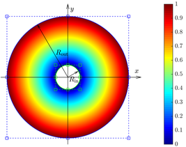
The first example considers the Couette flow around two infinite coaxial circular cylinders centred at the origin and with radius Rinsubscript𝑅inR_{\text{in}} and Routsubscript𝑅outR_{\text{out}} respectively, with Rin<Routsubscript𝑅insubscript𝑅outR_{\text{in}}<R_{\text{out}}, as represented in Figure 4. The boundary conditions correspond to known angular velocities, ΩinsubscriptΩin\Omega_{\text{in}} and ΩoutsubscriptΩout\Omega_{\text{out}}, at Rinsubscript𝑅inR_{\text{in}} and Routsubscript𝑅outR_{\text{out}}, respectively.

Refer to caption
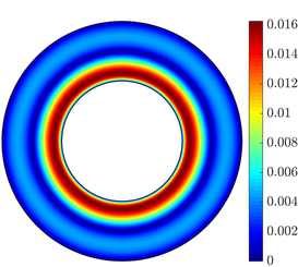
Figure 4: Computational domain for the solution of the rotating Couette flow and magnitude of the velocity of the analytical solution.

It is worth noting that the pressure must be specified at a point to remove its indeterminacy, as only Dirichlet boundary conditions for the velocity are considered. Here the pressure is imposed at one point of the outer boundary.

The analytical solution for this problem is known [7]. The azimuthal component of the velocity is given by

vϕ=Rout2ΩoutRin2ΩinRout2Rin2r+(ΩinΩout)Rout2Rin2Rout2Rin21rsubscript𝑣italic-ϕsuperscriptsubscript𝑅out2subscriptΩoutsuperscriptsubscript𝑅in2subscriptΩinsuperscriptsubscript𝑅out2superscriptsubscript𝑅in2𝑟subscriptΩinsubscriptΩoutsuperscriptsubscript𝑅out2superscriptsubscript𝑅in2superscriptsubscript𝑅out2superscriptsubscript𝑅in21𝑟v_{\phi}=\frac{R_{\text{out}}^{2}\Omega_{\text{out}}-R_{\text{in}}^{2}\Omega_{\text{in}}}{R_{\text{out}}^{2}-R_{\text{in}}^{2}}r+\frac{(\Omega_{\text{in}}-\Omega_{\text{out}})R_{\text{out}}^{2}R_{\text{in}}^{2}}{R_{\text{out}}^{2}-R_{\text{in}}^{2}}\frac{1}{r} (24)

where r=𝒙2𝑟subscriptnorm𝒙2r=\|\text{\boldmath$x$\unboldmath}\|_{2}. The magnitude of the velocity of the analytical solution is also depicted in Figure 4 for Ωin=0subscriptΩin0\Omega_{\text{in}}=0 and Ωout=1subscriptΩout1\Omega_{\text{out}}=1.

The inner radius Rinsubscript𝑅inR_{\text{in}} is considered an extra parameter within the proposed PGD framework and the objective is to find, in the off-line stage, the generalised velocity and pressure fields for Rin[1,2.5]subscript𝑅in12.5R_{\text{in}}\in[1,2.5]. It is worth noting that the variation of the inner radius induces the variation of the eight control points (i.e. 16 parameters in two dimensions) of the NURBS curve describing the inner circle, as represented in Figure 4. However, as mentioned in Remark 2, the motion of these control points can be controlled by a single parameter μ𝜇\mu representing the variation of the radius of the inner circle.

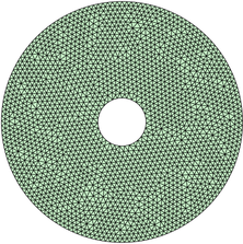
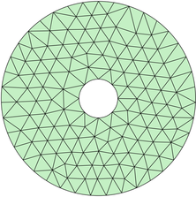
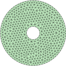
In this example the reference configuration corresponds to Rin=1subscript𝑅in1R_{\text{in}}=1 and Rout=5subscript𝑅out5R_{\text{out}}=5 and μ1=[0,1.5]𝜇subscript101.5\mu\in\mathcal{I}_{1}=[0,1.5]. Three unstructured triangular meshes of the reference domain, with 251, 1,023 and 4,256 elements respectively, are represented in Figure 5. These meshes are generated using the technique proposed in [30] to guarantee that elements without an edge on a curved boundary can be mapped to a reference triangle using an affine mapping.
Refer to caption
(a) Mesh 1
Refer to caption
(b) Mesh 2
Refer to caption
(c) Mesh 3
Figure 5: Three unstructured triangular meshes of the reference domain used for the solution of the Couette flow problem.

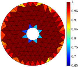
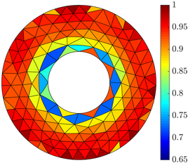
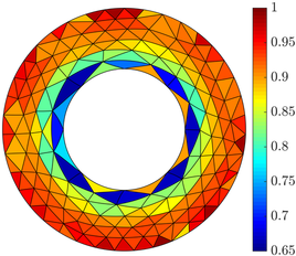
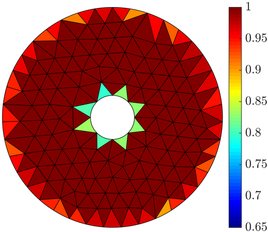
The quality of the coarsest mesh of the reference domain, measured using the scaled Jacobian [33], is represented in Figure 6.
Refer to caption
(a) k=2𝑘2k=2
Refer to caption
(b) k=3𝑘3k=3
Refer to caption
(c) k=4𝑘4k=4
Figure 6: Quality of the coarsest mesh of the reference domain, shown in Figure 5 (a), using different degrees of approximation.

The minimum quality observed is, as expected near the inner boundary where the elements show the maximum distortion.

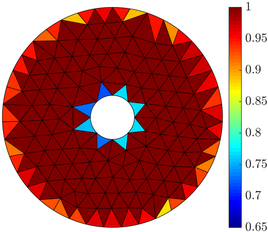
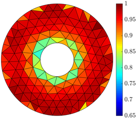
Figure 7 shows the deformed configuration for three values of the parameter μ𝜇\mu, namely μ=0.5𝜇0.5\mu=0.5, μ=1𝜇1\mu=1 and μ=1.5𝜇1.5\mu=1.5. These plots also represent the quality of the deformed mesh obtained by using the elastic analogy described in Section 4.4.
Refer to caption
(a) μ=0.5𝜇0.5\mu=0.5
Refer to caption
(b) μ=1𝜇1\mu=1
Refer to caption
(c) μ=1.5𝜇1.5\mu=1.5
Figure 7: Quality of the coarsest mesh of the deformed domain with k=4𝑘4k=4 for different values of the parameter μ𝜇\mu.

In all cases, the minimum quality is higher than 0.65.

To further illustrate the robustness of the mesh deformation technique employed within the proposed PGD framework, Figure 8 shows the evolution of the quality of the deformed meshes as a function of the parameter μ𝜇\mu using four different meshes and three different degrees of approximation.

Refer to caption
(a) k=2𝑘2k=2
Refer to caption
(b) k=3𝑘3k=3
Refer to caption
(c) k=4𝑘4k=4
Figure 8: Evolution of the quality of the deformed meshes corresponding to the reference mesh of Figure 5 (a) as a function of the parameter μ𝜇\mu using different meshes and degrees of approximation.

As expected, the worst case scenario corresponds to the maximum deformation induced by a parameter μ=1.5𝜇1.5\mu=1.5, but in all cases the minimum quality is always higher than 0.6. Furthermore, it is worth noting that the influence of the parameter μ𝜇\mu on the quality of the deformed meshes is less important for finer meshes.

A crucial aspect of the proposed PGD strategy is the separation of the matrix 𝐇𝝁subscript𝐇𝝁\mathbf{H}_{\text{\boldmath$\mu$\unboldmath}} defined in Equation (6). As discussed previously, 𝐇𝝁subscript𝐇𝝁\mathbf{H}_{\text{\boldmath$\mu$\unboldmath}} does not generally admit an exact separable expression and therefore a separable approximation is computed here via the higher-order PGD-projection [22].

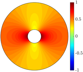
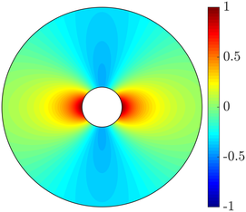
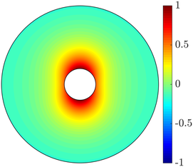
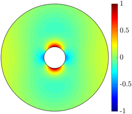
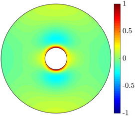
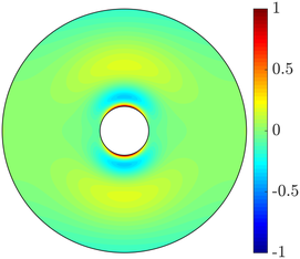
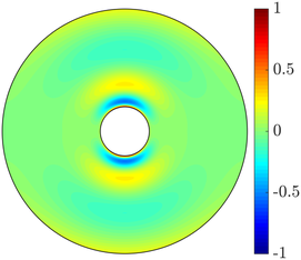
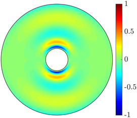
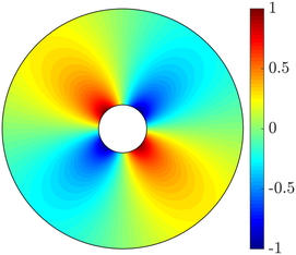
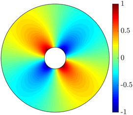
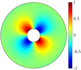
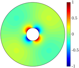
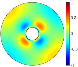
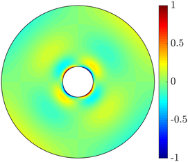
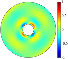
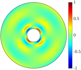
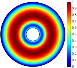
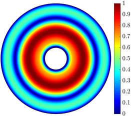
Figure 9 shows the first eight normalised spatial modes of the component [𝐇𝝁]11subscriptdelimited-[]subscript𝐇𝝁11[\mathbf{H}_{\text{\boldmath$\mu$\unboldmath}}]_{11}.

Refer to caption
(a) m=1𝑚1m=1
Refer to caption
(b) m=2𝑚2m=2
Refer to caption
(c) m=3𝑚3m=3
Refer to caption
(d) m=4𝑚4m=4
Refer to caption
(e) m=5𝑚5m=5
Refer to caption
(f) m=6𝑚6m=6
Refer to caption
(g) m=7𝑚7m=7
Refer to caption
(h) m=8𝑚8m=8
Figure 9: First eight normalised spatial modes of [𝐇𝝁]11subscriptdelimited-[]subscript𝐇𝝁11[\mathbf{H}_{\text{\boldmath$\mu$\unboldmath}}]_{11} on the mesh of Figure 5 (c) with 800 elements in the parametric dimension and with k=4𝑘4k=4.

The results suggest that the first two modes capture the main global features of [𝐇𝝁]11subscriptdelimited-[]subscript𝐇𝝁11[\mathbf{H}_{\text{\boldmath$\mu$\unboldmath}}]_{11}, whereas the rest of modes capture the local variations near the inner circle. The results for the second diagonal component, [𝐇𝝁]22subscriptdelimited-[]subscript𝐇𝝁22[\mathbf{H}_{\text{\boldmath$\mu$\unboldmath}}]_{22}, not displayed for brevity, show the same behaviour but with the expected rotation of 90 degrees due to the symmetry of the domain and the displacement field. Similarly, Figure 10 shows the first eight normalised spatial modes of the component [𝐇𝝁]12subscriptdelimited-[]subscript𝐇𝝁12[\mathbf{H}_{\text{\boldmath$\mu$\unboldmath}}]_{12}.

Refer to caption
(a) m=1𝑚1m=1
Refer to caption
(b) m=2𝑚2m=2
Refer to caption
(c) m=3𝑚3m=3
Refer to caption
(d) m=4𝑚4m=4
Refer to caption
(e) m=5𝑚5m=5
Refer to caption
(f) m=6𝑚6m=6
Refer to caption
(g) m=7𝑚7m=7
Refer to caption
(h) m=8𝑚8m=8
Figure 10: First eight normalised spatial modes of [𝐇𝝁]12subscriptdelimited-[]subscript𝐇𝝁12[\mathbf{H}_{\text{\boldmath$\mu$\unboldmath}}]_{12} on the mesh of Figure 5 (c) with 800 elements in the parametric dimension and with k=4𝑘4k=4.

The results show, again how the first modes capture the global behaviour of the component [𝐇𝝁]12subscriptdelimited-[]subscript𝐇𝝁12[\mathbf{H}_{\text{\boldmath$\mu$\unboldmath}}]_{12}, whereas the last modes show relevant spatial variations in the close vicinity of the inner circle.

The first eight normalised parametric modes of 𝐇𝝁subscript𝐇𝝁\mathbf{H}_{\text{\boldmath$\mu$\unboldmath}} are represented in Figure 11.

Refer to caption
Figure 11: First eight parametric modes of 𝐇𝝁subscript𝐇𝝁\mathbf{H}_{\text{\boldmath$\mu$\unboldmath}} on the mesh of Figure 5 (c) with 800 elements in the parametric dimension and with k=4𝑘4k=4.

It is worth recalling that the same parametric modes are associated to all the components of the matrix 𝐇𝝁subscript𝐇𝝁\mathbf{H}_{\text{\boldmath$\mu$\unboldmath}}.

The amplitude, αmsubscript𝛼𝑚\alpha_{m}, corresponding to the mode m𝑚m of the separation of 𝐇𝝁subscript𝐇𝝁\mathbf{H}_{\text{\boldmath$\mu$\unboldmath}}, is computed as the product of the Euclidean norms of the spatial and parametric functions. Figure 12 shows the amplitudes of [𝐇𝝁]11subscriptdelimited-[]subscript𝐇𝝁11[\mathbf{H}_{\text{\boldmath$\mu$\unboldmath}}]_{11} using three different meshes and three different degrees of approximation.

Refer to caption
(a) k=2𝑘2k=2
Refer to caption
(b) k=3𝑘3k=3
Refer to caption
(c) k=4𝑘4k=4
Figure 12: Evolution of the amplitude of the spatial modes αmsubscript𝛼𝑚\alpha_{m} of the matrix 𝐇𝝁subscript𝐇𝝁\mathbf{H}_{\text{\boldmath$\mu$\unboldmath}} using different meshes and degrees of approximation.

The results show that, for this example, the number of terms required to obtain a separable approximation of the matrix 𝐇𝝁subscript𝐇𝝁\mathbf{H}_{\text{\boldmath$\mu$\unboldmath}} using the higher-order PGD-projection is completely independent on the spatial discretisation. In all cases, 12 modes provide a decrease in the amplitude αmsubscript𝛼𝑚\alpha_{m} of exactly 13 orders of magnitude and the amplitude is the same in all meshes and for all degrees of approximation.

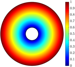
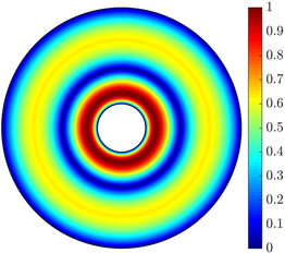
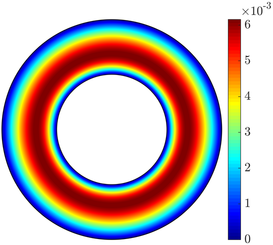
Using the separation of the matrix 𝐇𝝁subscript𝐇𝝁\mathbf{H}_{\text{\boldmath$\mu$\unboldmath}}, the rotating Couette flow problem is solved to obtain the generalised solution of the Stokes problem. The first eight normalised spatial modes of the magnitude of the velocity field are shown in Figure 13. The simulation was performed using the mesh of Figure 5 (c), 800 equally-spaced elements in 1=[0,1.5]subscript101.5\mathcal{I}_{1}=[0,1.5] and a degree of approximation k=4𝑘4k=4.

Refer to caption
(a) m=1𝑚1m=1
Refer to caption
(b) m=2𝑚2m=2
Refer to caption
(c) m=3𝑚3m=3
Refer to caption
(d) m=4𝑚4m=4
Refer to caption
(e) m=5𝑚5m=5
Refer to caption
(f) m=6𝑚6m=6
Refer to caption
(g) m=7𝑚7m=7
Refer to caption
(h) m=8𝑚8m=8
Figure 13: First eight normalised spatial modes of the magnitude of the velocity computed on the mesh of Figure 5 (c), 800 elements in the parametric dimension and a degree of approximation k=4𝑘4k=4.

The solution of the coaxial Couette flow problem requires imposing Dirichlet boundary conditions for the velocity at the inner and outer boundaries of the spatial domain. This is implemented within the PGD framework by adding one initial mode that fulfils the non-homogeneous Dirichlet boundary conditions. Its spatial part is computed as the solution of the Stokes problem at the reference mesh and its parametric component is taken as a constant function equal to one. The next PGD modes are computed by imposing homogeneous Dirichlet boundary conditions, ensuring that the separated PGD solution satisfies the required Dirichlet boundary conditions.

The first eight normalised parametric modes associated to the spatial modes of Figure 13 are represented in Figure 14.

Refer to caption
Figure 14: First eight parametric modes of the rotating Couette flow on the mesh of Figure 5 (c) with 800 elements in the parametric dimension and with k=4𝑘4k=4.

It is worth recalling that the same parametric mode is associated to all the components of the velocity and the pressure fields. The results reveal that the parametric modes of the velocity field show a similar behaviour compared to the parametric modes of the separation of 𝐇𝝁subscript𝐇𝝁\mathbf{H}_{\text{\boldmath$\mu$\unboldmath}}, shown in Figure 11. The first two modes are smooth whereas the next modes, that contribute less to the global solution, show a more oscillatory character.

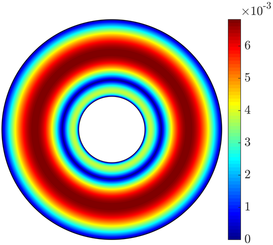
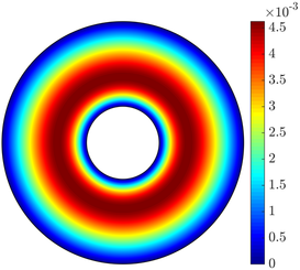
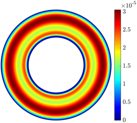
To illustrate the gain in accuracy as the number of modes increases, Figure 15 shows the absolute value of the error in the magnitude of the velocity computed with the proposed PGD approach using N𝑁N modes for different values of the parameter μ𝜇\mu.

Refer to caption
(a) μ=0.5𝜇0.5\mu=0.5, N=1𝑁1N=1
Refer to caption
(b) μ=0.5𝜇0.5\mu=0.5, N=2𝑁2N=2
Refer to caption
(c) μ=0.5𝜇0.5\mu=0.5, N=4𝑁4N=4
Refer to caption
(d) μ=1𝜇1\mu=1, N=1𝑁1N=1
Refer to caption
(e) μ=1𝜇1\mu=1, N=2𝑁2N=2
Refer to caption
(f) μ=1𝜇1\mu=1, N=4𝑁4N=4
Refer to caption
(g) μ=1.5𝜇1.5\mu=1.5, N=1𝑁1N=1
Refer to caption
(h) μ=1.5𝜇1.5\mu=1.5, N=2𝑁2N=2
Refer to caption
(i) μ=1.5𝜇1.5\mu=1.5, N=4𝑁4N=4
Figure 15: Absolute value of the error in the magnitude of the velocity computed with the proposed PGD approach using N𝑁N modes for different values of the parameter μ𝜇\mu. The computation has been performed on the mesh of Figure 5 (c), with 800 elements in the parametric dimension and a degree of approximation k=4𝑘4k=4.

The computation has been performed on the mesh of Figure 5 (c), with 800 elements in the parametric dimension and a degree of approximation k=4𝑘4k=4. In all cases, the results illustrate that the computation with four modes is almost three orders of magnitude more accurate than using a single mode.

To further analyse the accuracy of the proposed PGD approach when the number of modes is increased, the relative error in the 2(Ω×1)subscript2Ωsubscript1\mathcal{L}_{2}(\Omega\times\mathcal{I}_{1}) norm, defined as

εPGD=(1Ω(𝒖PGD𝒖)(𝒖PGD𝒖)𝑑Ω𝑑μ1Ω𝒖𝒖𝑑Ω𝑑μ)1/2,subscript𝜀PGDsuperscriptsubscriptsubscript1subscriptΩsubscript𝒖PGD𝒖subscript𝒖PGD𝒖differential-dΩdifferential-d𝜇subscriptsubscript1subscriptΩ𝒖𝒖differential-dΩdifferential-d𝜇12\varepsilon_{\texttt{PGD}}=\left(\frac{\displaystyle\int_{\mathcal{I}_{1}}\int_{\Omega}(\text{\boldmath$u$\unboldmath}_{\texttt{PGD}}-\text{\boldmath$u$\unboldmath})\cdot(\text{\boldmath$u$\unboldmath}_{\texttt{PGD}}-\text{\boldmath$u$\unboldmath})d\Omega\,d\mu}{\displaystyle\int_{\mathcal{I}_{1}}\int_{\Omega}\text{\boldmath$u$\unboldmath}\cdot\text{\boldmath$u$\unboldmath}\,d\Omega\,d\mu}\right)^{1/2}, (25)

is studied. Figure 16 depicts the evolution of εPGDsubscript𝜀PGD\varepsilon_{\texttt{PGD}} as a function of the number of PGD modes for three different degrees of approximation and four different meshes.

Refer to caption
(a) k=2𝑘2k=2
Refer to caption
(b) k=3𝑘3k=3
Refer to caption
(c) k=4𝑘4k=4
Figure 16: Error of the PGD solution as a function of the number of PGD modes using three different meshes for the solution of the Couette flow problem. The discontinuous line represents the error using standard FEM.

The discontinuous lines in Figure 16 show the relative error of the standard FEM solution measured in the 2(Ω×1)subscript2Ωsubscript1\mathcal{L}_{2}(\Omega\times\mathcal{I}_{1}) norm. The evaluation of the error of the FEM solution in the 2(Ω×1)subscript2Ωsubscript1\mathcal{L}_{2}(\Omega\times\mathcal{I}_{1}) norm requires the solution of as many FEM problems as the number of elements in the parametric dimension used by the PGD approach, multiplied by the number of integration points within each element.

The results clearly illustrate the increased level of accuracy as the number of modes is increased. In addition, the increased accuracy induced by the use of finer meshes or higher degrees of approximation can be observed. It worth noting that the PGD solution achieves its maximum accuracy (i.e. the accuracy of a standard FEM solution) using a low number of modes. For coarse meshes, the maximum accuracy of the PGD solution is achieved with three or four modes. For finer meshes, the PGD approach provides accurate results with only three or four modes and requires between six and 11 modes to reach the same level of error as the standard FEM solution.

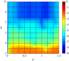
Next, the accuracy of the PGD solution for different values of the parameter μ𝜇\mu is studied. Figure 17 shows the difference between the PGD solution and the FEM solution, in logarithmic scale, as a function of the parameter μ𝜇\mu and the number of PGD modes using different degrees of approximation.

Refer to caption
(a) k=2𝑘2k=2
Refer to caption
(b) k=3𝑘3k=3
Refer to caption
(c) k=4𝑘4k=4
Figure 17: Difference between the PGD solution and the FEM solution, in logarithmic scale, as a function of the parameter μ𝜇\mu and the number of PGD modes using different degrees of approximation.

The results show that the accuracy of the PGD solution depends only weakly on the value of the parameter selected. For values of μ=0𝜇0\mu=0, corresponding to the undeformed configuration, the error is lower for a moderate number of PGD modes. This is expected because for μ=0𝜇0\mu=0 the displacement function 𝒅𝒅d is null and the Jacobian 𝐉𝝁subscript𝐉𝝁\mathbf{J}_{\!\text{\boldmath$\mu$\unboldmath}} is equal to the identity matrix. But for a large enough number of modes, the difference between the PGD solution and the FEM solution shows very little dependence on the value of μ𝜇\mu, illustrating the robustness of the proposed PGD approach.

The last numerical study for the rotation Couette flow considers a mesh convergence analysis for the proposed PGD approach. The PGD solution is computed on the three meshes shown in Figure 5 using three different orders of approximation. Figure 18 shows the evolution of the relative error in the 2(Ω×1)subscript2Ωsubscript1\mathcal{L}_{2}(\Omega\times\mathcal{I}_{1}) norm, εPGDsubscript𝜀PGD\varepsilon_{\texttt{PGD}}, as a function of the characteristic element size hh.

Refer to caption
Figure 18: Relative error between the PGD and analytical solutions in the 2(Ω×1)subscript2Ωsubscript1\mathcal{L}_{2}(\Omega\times\mathcal{I}_{1}) norm as a function of the characteristic element size hh for different degrees of approximation k𝑘k.

For each simulation the minimum number of PGD modes required to achieve the maximum accuracy is considered, as described earlier when presenting the results of Figure 16. The results show that, when enough modes are considered within the PGD framework, the error εPGDsubscript𝜀PGD\varepsilon_{\texttt{PGD}} converges with near an optimal rate hk+1superscript𝑘1h^{k+1}.

5.2 Stokes flow around two circular cylinders

The second example is inspired by the studies of [31, 1] on the analysis of micro-swimmers. The problem involves the computation of the Stokes flow in a rectangular channel of dimension 40×14401440\times 14 with two circular cylinders of radius R1subscript𝑅1R_{1} and R2subscript𝑅2R_{2}, where the distance between their centres is D𝐷D, as represented in Figure 19. Slip boundary conditions are considered on the surface of the cylinders, a free slip boundary condition on the top and bottom boundaries, a imposed horizontal velocity of unit magnitude on the left boundary and a homogeneous Neumann boundary condition on the right part of the boundary.

Refer to caption
Figure 19: Detail of the computational domain for the solution of the Stokes flow around two circular cylinders.

The geometric parameters considered are the radius of the cylinders and the distance between their centres. In addition, as done in the context of microswimmers, it is assumed that the variation of the two radius is linked so that R12+R22superscriptsubscript𝑅12superscriptsubscript𝑅22R_{1}^{2}+R_{2}^{2} remains constant, that is the area enclosed by the two cylinders is constant. It is worth noting that the variation of these geometric parameters involve the variation of all the control points (i.e. 32 parameters) of the two NURBS describing the circles represented in Figure 19. However, as done in the previous example, it is possible to re-parametrise the motion in terms of only two parameters, μ11=[1,1]subscript𝜇1subscript111\mu_{1}\in\mathcal{I}_{1}=[-1,1] which controls the radius of the cylinders and μ22=[1,1]subscript𝜇2subscript211\mu_{2}\in\mathcal{I}_{2}=[-1,1] controlling the distance between the cylinders.

The reference configuration corresponds to R1=R2=0.8subscript𝑅1subscript𝑅20.8R_{1}=R_{2}=0.8 (μ1=0subscript𝜇10\mu_{1}=0) and D=14𝐷14D=14 (μ2=0subscript𝜇20\mu_{2}=0). The minimum and maximum values for the radius of the cylinders are 0.3578 (μ1=1subscript𝜇11\mu_{1}=-1) and 1.0733 (μ1=1subscript𝜇11\mu_{1}=1) which, given the link between R1subscript𝑅1R_{1} and R2subscript𝑅2R_{2}, correspond to the cases where the area of one of the circles is 90% and 10% respectively of the total area occupied by both circles. For the distance, the maximum and minimum values are 15.5 (μ2=1subscript𝜇21\mu_{2}=-1) and 12.5 (μ2=1subscript𝜇21\mu_{2}=1) respectively.

A computational mesh with 2,338 triangular elements is generated for the reference configuration. For a cubic degree of approximation (for geometry and velocity), Figure 20 shows the quality of the mesh for the reference configuration and for two deformed configurations corresponding to the extreme cases with μ1=μ2=1subscript𝜇1subscript𝜇21\mu_{1}=\mu_{2}=-1 and μ1=μ2=1subscript𝜇1subscript𝜇21\mu_{1}=\mu_{2}=1.

Refer to caption
(a) μ1=μ2=0subscript𝜇1subscript𝜇20\mu_{1}=\mu_{2}=0
Refer to caption
(b) μ1=μ2=1subscript𝜇1subscript𝜇21\mu_{1}=\mu_{2}=-1
Refer to caption
(c) μ1=μ2=1subscript𝜇1subscript𝜇21\mu_{1}=\mu_{2}=1
Figure 20: Computational mesh and quality for three values of the geometric parameters μ1subscript𝜇1\mu_{1} and μ2subscript𝜇2\mu_{2}.

It can be observed that, even for the large deformations corresponding to the extreme cases of Figures 20 (b) and (c), the minimum quality (measured as the scaled Jacobian) is near 0.7, which is similar to the quality observed in the previous example for a simpler problem.

Next, the separation of the matrix 𝐇𝝁subscript𝐇𝝁\mathbf{H}_{\text{\boldmath$\mu$\unboldmath}}, defined in Equation (6), is considered. As discussed previously 𝐇𝝁subscript𝐇𝝁\mathbf{H}_{\text{\boldmath$\mu$\unboldmath}} does not generally admit an exact separable expression and therefore a separable approximation is computed here via the higher-order PGD-projection described in [22].

Figure 21 shows the first six normalised spatial modes of the component [𝐇𝝁]11subscriptdelimited-[]subscript𝐇𝝁11[\mathbf{H}_{\text{\boldmath$\mu$\unboldmath}}]_{11}.

Refer to caption
(a) m=1𝑚1m=1
Refer to caption
(b) m=2𝑚2m=2
Refer to caption
(c) m=3𝑚3m=3
Refer to caption
(d) m=4𝑚4m=4
Refer to caption
(e) m=5𝑚5m=5
Refer to caption
(f) m=6𝑚6m=6
Figure 21: First six normalised spatial modes of [𝐇𝝁]11subscriptdelimited-[]subscript𝐇𝝁11[\mathbf{H}_{\text{\boldmath$\mu$\unboldmath}}]_{11} on the mesh of Figure 20 (a) with 25 elements in 1subscript1\mathcal{I}_{1}, 45 elements in 2subscript2\mathcal{I}_{2} and with k=4𝑘4k=4.

Similarly, Figures 22 and 23 show the first six normalised spatial modes of the component [𝐇𝝁]12subscriptdelimited-[]subscript𝐇𝝁12[\mathbf{H}_{\text{\boldmath$\mu$\unboldmath}}]_{12} and [𝐇𝝁]22subscriptdelimited-[]subscript𝐇𝝁22[\mathbf{H}_{\text{\boldmath$\mu$\unboldmath}}]_{22} respectively.

Refer to caption
(a) m=1𝑚1m=1
Refer to caption
(b) m=2𝑚2m=2
Refer to caption
(c) m=3𝑚3m=3
Refer to caption
(d) m=4𝑚4m=4
Refer to caption
(e) m=5𝑚5m=5
Refer to caption
(f) m=6𝑚6m=6
Figure 22: First six normalised spatial modes of [𝐇𝝁]12subscriptdelimited-[]subscript𝐇𝝁12[\mathbf{H}_{\text{\boldmath$\mu$\unboldmath}}]_{12} on the mesh of Figure 20 (a) with 25 elements in 1subscript1\mathcal{I}_{1}, 45 elements in 2subscript2\mathcal{I}_{2} and with k=4𝑘4k=4.
Refer to caption
(a) m=1𝑚1m=1
Refer to caption
(b) m=2𝑚2m=2
Refer to caption
(c) m=3𝑚3m=3
Refer to caption
(d) m=4𝑚4m=4
Refer to caption
(e) m=5𝑚5m=5
Refer to caption
(f) m=6𝑚6m=6
Figure 23: First six normalised spatial modes of [𝐇𝝁]22subscriptdelimited-[]subscript𝐇𝝁22[\mathbf{H}_{\text{\boldmath$\mu$\unboldmath}}]_{22} on the mesh of Figure 20 (a) with 25 elements in 1subscript1\mathcal{I}_{1}, 45 elements in 2subscript2\mathcal{I}_{2} and with k=4𝑘4k=4.

It is worth noting that some of the modes in Figure 21 resemble the modes obtained in the previous example and represented in Figure 9, whereas other modes display a completely different spatial variation. This indicates that the similar modes are the ones that carry information about the change of the radius of the cylinders whereas the different ones are related to the variation of the distance between the cylinders.

Contrary to the previous example, it is apparent that more modes are necessary to describe the global behaviour of the matrix 𝐇𝝁subscript𝐇𝝁\mathbf{H}_{\text{\boldmath$\mu$\unboldmath}}. For instance, in the previous example only two modes were needed to describe the global information of the matrix 𝐇𝝁subscript𝐇𝝁\mathbf{H}_{\text{\boldmath$\mu$\unboldmath}} whereas now the fourth mode of all the components of 𝐇𝝁subscript𝐇𝝁\mathbf{H}_{\text{\boldmath$\mu$\unboldmath}} and the fifth mode of [𝐇𝝁]22subscriptdelimited-[]subscript𝐇𝝁22[\mathbf{H}_{\text{\boldmath$\mu$\unboldmath}}]_{22} contain global information. Also, contrary to the previous example, it is interesting to observe the different behaviour of the modes associated to the diagonal terms of the matrix 𝐇𝝁subscript𝐇𝝁\mathbf{H}_{\text{\boldmath$\mu$\unboldmath}}. This is due to the more complex motion induced by the geometric parameters, compared to the previous example.

The first eight normalised parametric modes of 𝐇𝝁subscript𝐇𝝁\mathbf{H}_{\text{\boldmath$\mu$\unboldmath}} are represented in Figure 24.

Refer to caption
(a) μ1subscript𝜇1\mu_{1}
Refer to caption
(b) μ2subscript𝜇2\mu_{2}
Figure 24: First eight parametric modes of 𝐇𝝁subscript𝐇𝝁\mathbf{H}_{\text{\boldmath$\mu$\unboldmath}} on the mesh of Figure 20 (a) with 25 elements in 1subscript1\mathcal{I}_{1}, 45 elements in 2subscript2\mathcal{I}_{2} and with k=4𝑘4k=4.

It is worth recalling that the same parametric modes are associated to all the components of the matrix 𝐇𝝁subscript𝐇𝝁\mathbf{H}_{\text{\boldmath$\mu$\unboldmath}}. It is interesting to observe the similar qualitative behaviour of the parametric modes of μ1subscript𝜇1\mu_{1}, represented in Figure 24 (a), and the parametric modes obtained in the previous example, represented in Figure 11. This is expected as in both cases these modes are related to the variation of the radius of a circle. The parametric modes associated to the distance between the cylinders, represented in Figure 24 (b), display a less oscillatory character than the modes associated to the variation of the radius of a circle.

To illustrate the increased complexity due to the introduction of two geometric parameters, Figure 25 shows the amplitude, αmsubscript𝛼𝑚\alpha_{m}, corresponding to the mode m𝑚m of the separation of 𝐇𝝁subscript𝐇𝝁\mathbf{H}_{\text{\boldmath$\mu$\unboldmath}}, computed as the product of the Euclidean norms of the spatial and parametric functions.

The amplitude, αmsubscript𝛼𝑚\alpha_{m}, corresponding to the mode m𝑚m of the separation of 𝐇𝝁subscript𝐇𝝁\mathbf{H}_{\text{\boldmath$\mu$\unboldmath}}, is computed as the product of the Euclidean norms of the spatial and parametric functions. Figure 12 shows the amplitudes of [𝐇𝝁]11subscriptdelimited-[]subscript𝐇𝝁11[\mathbf{H}_{\text{\boldmath$\mu$\unboldmath}}]_{11} using four different meshes and three different degrees of approximation.

Refer to caption
Figure 25: Evolution of the amplitude of the spatial modes αmsubscript𝛼𝑚\alpha_{m} of the matrix 𝐇𝝁subscript𝐇𝝁\mathbf{H}_{\text{\boldmath$\mu$\unboldmath}} using different degrees of approximation.
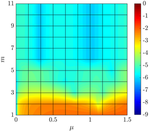
The results show that, for this example, the number of terms required to obtain a separable approximation of the matrix 𝐇𝝁subscript𝐇𝝁\mathbf{H}_{\text{\boldmath$\mu$\unboldmath}} using the higher-order PGD-projection is significantly higher than in the previous example. To provide a decrease in the amplitude αmsubscript𝛼𝑚\alpha_{m} of six orders of magnitude the number of modes vary from 50 and 63 for an order of approximation ranging from k=2𝑘2k=2 to k=4𝑘4k=4, showing again that the number of modes is not highly dependent upon the spatial discretisation.

Using the separation of the matrix 𝐇𝝁subscript𝐇𝝁\mathbf{H}_{\text{\boldmath$\mu$\unboldmath}}, the Stokes flow around the two cylinders is computed with the proposed approach to obtain the generalised solution. The first six normalised spatial modes of the magnitude of the velocity and the pressure fields are shown in Figure 26.

Refer to caption
(a) Velocity, m=1𝑚1m=1
Refer to caption
(b) Pressure, m=1𝑚1m=1
Refer to caption
(c) Velocity, m=2𝑚2m=2
Refer to caption
(d) Pressure, m=2𝑚2m=2
Refer to caption
(e) Velocity, m=3𝑚3m=3
Refer to caption
(f) Pressure, m=3𝑚3m=3
Refer to caption
(g) Velocity, m=4𝑚4m=4
Refer to caption
(h) Pressure, m=4𝑚4m=4
Refer to caption
(i) Velocity, m=5𝑚5m=5
Refer to caption
(j) Pressure, m=5𝑚5m=5
Refer to caption
(k) Velocity, m=6𝑚6m=6
Refer to caption
(l) Pressure, m=6𝑚6m=6
Figure 26: First six normalised spatial modes of the magnitude of the velocity (left) and pressure (right) computed on the mesh of Figure 20 (a) with 25 elements in 1subscript1\mathcal{I}_{1}, 45 elements in 2subscript2\mathcal{I}_{2} and with k=4𝑘4k=4.

The simulation was performed using the mesh of Figure 20 (a), 25 equally-spaced elements in 1=[1,1]subscript111\mathcal{I}_{1}=[-1,1], 45 equally-spaced elements in 2=[1,1]subscript211\mathcal{I}_{2}=[-1,1] and a degree of approximation k=4𝑘4k=4.

The first eight normalised parametric modes associated to the spatial modes of Figure 26 are represented in Figure 27.

Refer to caption
(a) μ1subscript𝜇1\mu_{1}
Refer to caption
(b) μ2subscript𝜇2\mu_{2}
Figure 27: First eight parametric modes of the Stokes flow around two circular cylinders on the mesh of Figure 20 (a) with 25 elements in 1subscript1\mathcal{I}_{1}, 45 elements in 2subscript2\mathcal{I}_{2} and with k=4𝑘4k=4.

It is worth recalling that the same parametric mode is associated to all the components of the velocity and the pressure fields.

Contrary to the previous example, it can be observed that the spatial modes for the velocity and the pressure do not resemble the spatial modes of the matrix 𝐇𝝁subscript𝐇𝝁\mathbf{H}_{\text{\boldmath$\mu$\unboldmath}}, illustrating the increased complexity of the current problem. In addition, it is worth noting that the parametric modes associated to the first parameter μ1subscript𝜇1\mu_{1} shows a more oscillatory character than μ2subscript𝜇2\mu_{2} when the separation of the matrix 𝐇𝝁subscript𝐇𝝁\mathbf{H}_{\text{\boldmath$\mu$\unboldmath}} is studied (as shown in Figure 24), whereas the the second parameter μ2subscript𝜇2\mu_{2} shows a more oscillatory character than μ1subscript𝜇1\mu_{1} when the separation of the velocity and pressure is considered (as shown in Figure 27). This indicates that the flow around the two cylinders changes slowly when the radius of the cylinders is varied whereas the flow changes more rapidly when the distance between the cylinders is varied.

Next, the solutions obtained with the proposed PGD framework are represented for different values of the geometric parameters. Figure 28 shows the magnitude of the velocity and the pressure fields for the three configurations shown in Figure 20.

Refer to caption
(a) Velocity, μ1=μ2=0subscript𝜇1subscript𝜇20\mu_{1}=\mu_{2}=0
Refer to caption
(b) Pressure, μ1=μ2=0subscript𝜇1subscript𝜇20\mu_{1}=\mu_{2}=0
Refer to caption
(c) Velocity, μ1=μ2=1subscript𝜇1subscript𝜇21\mu_{1}=\mu_{2}=-1
Refer to caption
(d) Pressure, μ1=μ2=1subscript𝜇1subscript𝜇21\mu_{1}=\mu_{2}=-1
Refer to caption
(e) Velocity, μ1=μ2=1subscript𝜇1subscript𝜇21\mu_{1}=\mu_{2}=1
Refer to caption
(f) Pressure, μ1=μ2=1subscript𝜇1subscript𝜇21\mu_{1}=\mu_{2}=1
Figure 28: Magnitude of the velocity (left) and pressure (right) computed on the three configurations shown in Figure 20 with 25 elements in 1subscript1\mathcal{I}_{1}, 45 elements in 2subscript2\mathcal{I}_{2} and with k=4𝑘4k=4.

To illustrate the accuracy of the proposed approach, Figure 29 shows the difference between the standard FE solution and the PGD solution for the magnitude of the velocity and the pressure corresponding to the three configurations shown in Figure 20.

Refer to caption
(a) Velocity, μ1=μ2=0subscript𝜇1subscript𝜇20\mu_{1}=\mu_{2}=0
Refer to caption
(b) Pressure, μ1=μ2=0subscript𝜇1subscript𝜇20\mu_{1}=\mu_{2}=0
Refer to caption
(c) Velocity, μ1=μ2=1subscript𝜇1subscript𝜇21\mu_{1}=\mu_{2}=-1
Refer to caption
(d) Pressure, μ1=μ2=1subscript𝜇1subscript𝜇21\mu_{1}=\mu_{2}=-1
Refer to caption
(e) Velocity, μ1=μ2=1subscript𝜇1subscript𝜇21\mu_{1}=\mu_{2}=1
Refer to caption
(f) Pressure, μ1=μ2=1subscript𝜇1subscript𝜇21\mu_{1}=\mu_{2}=1
Figure 29: Difference between the standard FE solution and the PGD solution for the magnitude of the velocity (left) and pressure (right) computed on the three configurations shown in Figure 28.

For all the configurations, the results obtained with the proposed PGD framework are in excellent agreement with the results obtained using a standard FE solver. For the first configuration displayed in Figure 29, corresponding to μ1=μ2=0subscript𝜇1subscript𝜇20\mu_{1}=\mu_{2}=0, the difference between the magnitude of the velocity field using FEM and the PGD in the 2(Ω𝝁)subscript2superscriptΩ𝝁\mathcal{L}_{2}(\Omega^{\text{\boldmath$\mu$\unboldmath}}) norm is 0.0143 and the difference between the pressure field using FEM and the PGD in the 2(Ω𝝁)subscript2superscriptΩ𝝁\mathcal{L}_{2}(\Omega^{\text{\boldmath$\mu$\unboldmath}}) norm is 0.0277. For the second configuration of Figure 29, corresponding to μ1=μ2=1subscript𝜇1subscript𝜇21\mu_{1}=\mu_{2}=-1, the difference between the magnitude of the velocity and pressure fields using FEM and the PGD in the 2(Ω𝝁)subscript2superscriptΩ𝝁\mathcal{L}_{2}(\Omega^{\text{\boldmath$\mu$\unboldmath}}) norm are 0.0267 and 0.0592 respectively. Finally, for the last configuration of Figure 29, corresponding to μ1=μ2=1subscript𝜇1subscript𝜇21\mu_{1}=\mu_{2}=1, the difference between the magnitude of the velocity and pressure fields using FEM and the PGD in the 2(Ω𝝁)subscript2superscriptΩ𝝁\mathcal{L}_{2}(\Omega^{\text{\boldmath$\mu$\unboldmath}}) norm are 0.0218 and 0.0787 respectively. It is worth emphasising that the accurate results obtained, with differences between PGD and standard FE simulations lower than 8% for the whole range of geometric configurations, have been obtained with very coarse meshes in the parametric spaces, only 25 elements in 1subscript1\mathcal{I}_{1} and 45 elements in 2subscript2\mathcal{I}_{2}.

5.3 Stokes flow around an arbitrarily shaped vesicle

The last example is inspired by the study of vesicles suspended in a viscous flow presented in [32]. The characterisation of such flows is of interest in many biomechanical applications and the simulations often require the computation to be performed for a large variety of geometric configurations. This example is used to demonstrate the applicability of the proposed technique in three dimensions by using three geometric parameters that lead to substantial variations in the geometric model.

The problem considered here involves the simulation of the Stokes flow around an arbitrarily shaped vesicle in a channel of dimension 10×10×2010102010\times 10\times 20. Slip boundary conditions are considered on the surface of the vesicle, an imposed vertical velocity of unit magnitude in the inflow part of the boundary (z=10𝑧10z=-10), a homogeneous Neumann boundary condition on the outflow part of the boundary (z=10𝑧10z=10) and free slip boundary conditions on the remaining parts of the boundary.

The generic vesicle considered is modelled using a single degenerate cubic NURBS with 20 control points and four patches, as illustrated in Figure 30.
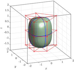
Refer to caption
Figure 30: Geometric model of a vesicle, showing the control net and the breaklines.

The control points are arranged in three groups, according to their z𝑧z coordinate being positive, zero or negative. The geometric parametrisation considers the motion of all the three groups independently by using three parameters, μ1subscript𝜇1\mu_{1}, μ2subscript𝜇2\mu_{2} and μ3subscript𝜇3\mu_{3} respectively. Each parameter is used to vary the radial position of the control points whilst maintaining its z𝑧z coordinate. For the control points with positive z𝑧z coordinate the radial coordinate is given by r+3μ1/4𝑟3subscript𝜇14r+3\mu_{1}/4 with μ1[1,1]subscript𝜇111\mu_{1}\in[-1,1]. Similarly for the control points with zero or positive z𝑧z coordinate the radial coordinate is r+3μ2/4𝑟3subscript𝜇24r+3\mu_{2}/4 and r+3μ3/4𝑟3subscript𝜇34r+3\mu_{3}/4 respectively, with μ2[1,1]subscript𝜇211\mu_{2}\in[-1,1] and μ3[1,1]subscript𝜇311\mu_{3}\in[-1,1].

The reference configuration, corresponding to 𝝁=(μ1,μ2,μ3)=(0,0,0)𝝁subscript𝜇1subscript𝜇2subscript𝜇3000\text{\boldmath$\mu$\unboldmath}=(\mu_{1},\mu_{2},\mu_{3})=(0,0,0), is shown in Figure 30.

The generalised PGD solution is computed using a tetrahedral mesh with 6,712 elements, 10 equally-spaced elements in each parametric interval 1=2=3=[1,1]subscript1subscript2subscript311\mathcal{I}_{1}=\mathcal{I}_{2}=\mathcal{I}_{3}=[-1,1] and a degree of approximation k=4𝑘4k=4.

To illustrate the variation in the geometry induced by the selected geometric parameters, Figure 31 shows six different geometric configurations using different values for the geometric parameters.
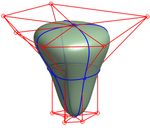
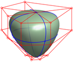
Refer to caption
(a) 𝝁=(1,1,1)𝝁111\text{\boldmath$\mu$\unboldmath}=(-1,-1,1)
Refer to caption
(b) 𝝁=(1,1,1)𝝁111\text{\boldmath$\mu$\unboldmath}=(-1,1,1)
Refer to caption
(c) 𝝁=(0,1,1)𝝁011\text{\boldmath$\mu$\unboldmath}=(0,-1,1)
Refer to caption
(d) 𝝁=(0,1,0)𝝁010\text{\boldmath$\mu$\unboldmath}=(0,1,0)
Refer to caption
(e) 𝝁=(1,0,1)𝝁101\text{\boldmath$\mu$\unboldmath}=(1,0,-1)
Refer to caption
(f) 𝝁=(1,0,0)𝝁100\text{\boldmath$\mu$\unboldmath}=(1,0,0)
Figure 31: Geometric model of six different vesicle obtained by deforming the reference configuration of Figure 30.

It can be observed that the variations of the control points considered lead to substantial changes in the geometric model. These variations induce a deformation of the mesh generated for the reference configuration, computed in a separated form by employing the strategy described in Section 4.4. Figure 32 shows six deformed meshes near the vesicle that correspond to the six variations of the geometric parameters depicted in Figure 31.
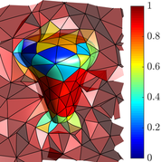
Refer to caption
(a) 𝝁=(1,1,1)𝝁111\text{\boldmath$\mu$\unboldmath}=(-1,-1,1)
Refer to caption
(b) 𝝁=(1,1,1)𝝁111\text{\boldmath$\mu$\unboldmath}=(-1,1,1)
Refer to caption
(c) 𝝁=(0,1,1)𝝁011\text{\boldmath$\mu$\unboldmath}=(0,-1,1)
Refer to caption
(d) 𝝁=(0,1,0)𝝁010\text{\boldmath$\mu$\unboldmath}=(0,1,0)
Refer to caption
(e) 𝝁=(1,0,1)𝝁101\text{\boldmath$\mu$\unboldmath}=(1,0,-1)
Refer to caption
(f) 𝝁=(1,0,0)𝝁100\text{\boldmath$\mu$\unboldmath}=(1,0,0)
Figure 32: Detail of the six deformed high-order meshes corresponding to the configurations shown in Figure 31.

The colours represent the quality of the elements, measured as the scaled Jacobian.

Following the strategy described in this work, the matrix 𝐇𝝁subscript𝐇𝝁\mathbf{H}_{\text{\boldmath$\mu$\unboldmath}} is separated first using the higher-order PGD-projection. To provide a decrease in the amplitude αmsubscript𝛼𝑚\alpha_{m} of five orders of magnitude, 50 modes are required in this example. It is worth noting that this is almost the same number of modes required for the previous two dimensional example to provide the same degree in the amplitude of the modes of the matrix 𝐇𝝁subscript𝐇𝝁\mathbf{H}_{\text{\boldmath$\mu$\unboldmath}}.

Using the separation of the matrix 𝐇𝝁subscript𝐇𝝁\mathbf{H}_{\text{\boldmath$\mu$\unboldmath}}, the Stokes flow around the vesicle is computed with the proposed approach to obtain the generalised solution. A total of 160 modes are computed, being the amplitude of the last mode three orders of magnitude lower than the amplitude of the first mode.

Figures 33 and 34 show the velocity and pressure fields for the six geometric configurations shown in Figure 31.
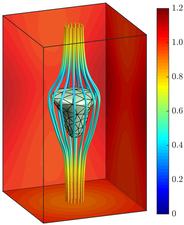
Refer to caption
(a) 𝝁=(1,1,1)𝝁111\text{\boldmath$\mu$\unboldmath}=(-1,-1,1)
Refer to caption
(b) 𝝁=(1,1,1)𝝁111\text{\boldmath$\mu$\unboldmath}=(-1,1,1)
Refer to caption
(c) 𝝁=(0,1,1)𝝁011\text{\boldmath$\mu$\unboldmath}=(0,-1,1)
Refer to caption
(d) 𝝁=(0,1,0)𝝁010\text{\boldmath$\mu$\unboldmath}=(0,1,0)
Refer to caption
(e) 𝝁=(1,0,1)𝝁101\text{\boldmath$\mu$\unboldmath}=(1,0,-1)
Refer to caption
(f) 𝝁=(1,0,0)𝝁100\text{\boldmath$\mu$\unboldmath}=(1,0,0)
Figure 33: Magnitude of the velocity and isolines for the six configurations shown in Figure 31.
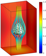
Refer to caption
(a) 𝝁=(1,1,1)𝝁111\text{\boldmath$\mu$\unboldmath}=(-1,-1,1)
Refer to caption
(b) 𝝁=(1,1,1)𝝁111\text{\boldmath$\mu$\unboldmath}=(-1,1,1)
Refer to caption
(c) 𝝁=(0,1,1)𝝁011\text{\boldmath$\mu$\unboldmath}=(0,-1,1)
Refer to caption
(d) 𝝁=(0,1,0)𝝁010\text{\boldmath$\mu$\unboldmath}=(0,1,0)
Refer to caption
(e) 𝝁=(1,0,1)𝝁101\text{\boldmath$\mu$\unboldmath}=(1,0,-1)
Refer to caption
(f) 𝝁=(1,0,0)𝝁100\text{\boldmath$\mu$\unboldmath}=(1,0,0)
Figure 34: Pressure field for the six configurations shown in Figure 31.
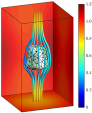
These configurations are obtained in the on-line phase as particularisations of the genearlised, six dimensional, PGD solution. Both the velocity and pressure fields illustrate the ability of the proposed PGD approach to capture significant changes in the flow field induced by geometric variations of the CAD model.

To quantify the accuracy of the proposed technique in a more complex problem in three dimensions and with three geometric parameters, the particularised solutions for the velocity and pressure are compared to standard finite element computations performed on the deformed configurations for the six cases displayed in Figures 33 and 34. For the velocity field, the difference between the PGD and the finite element solution, measured in the 2(Ω)subscript2Ω\mathcal{L}_{2}(\Omega) norm, is 0.7%, 0.8%, 0.8%, 0.4%, 0.6% and 0.7% for the six cases shown in Figure 33 respectively. Similarly, for the pressure field, the difference between the PGD and the finite element solution, measured in the 2(Ω)subscript2Ω\mathcal{L}_{2}(\Omega) norm, is 7%, 7%, 7%, 3%, 5% and 6% for the six cases shown in Figure 34 respectively. It is worth emphasising that the higher accuracy observed in the velocity is due to the use of a higher interpolation degree for the velocity field, compared to the pressure field, in order to satisfy the LBB conditions.

6 Concluding remarks

A computational framework for the computation of off-line solutions for a set of parameters describing the geometry of a domain has been presented. The proposed approach considers as parameters of the generalised PGD solution the control points of the CAD boundary representation of the computational domain. A mapping between a reference configuration and the current configuration is proposed by interpreting the geometric changes as a displacement field derived from a linear elastic problem. The key aspect of the proposed approach is that the displacement field is explicitly written in a separable form. This approach enables the incorporation of the PGD rationale in a high-order finite element context.

The potential of the proposed approach is shown for a variety of problems involving the solution of the Stokes equation in geometrically parametrised domains, both in two and three dimensions. The problems, of increasing difficulty show the optimal approximation properties of the method and its ability to accurately capture the flow features for significant changes of the geometric model. For the most complex problem considered in this work, the generalised solution computed with three geometric parameters in three dimensions show good agreement when compared to a standard finite element computation, with errors in the velocity field lower than 1% and errors in the pressure field below 8%.

Appendix A Integration within a CAD environment in 3D

In three dimensions, the boundary of the parameterized domain, Ω𝝁superscriptΩ𝝁\partial\Omega^{\text{\boldmath$\mu$\unboldmath}}, is assumed to be described by using a set NURBS surfaces {𝑺j𝝁}j=1,,Msubscriptsuperscriptsubscript𝑺𝑗𝝁𝑗1𝑀\{\text{\boldmath$S$\unboldmath}_{\!j}^{\text{\boldmath$\mu$\unboldmath}}\}_{j=1,\dotsc,M}, being M𝑀M the total number of surfaces, namely

Ω𝝁=j=1M𝑺j𝝁([0,1]2).superscriptΩ𝝁superscriptsubscript𝑗1𝑀superscriptsubscript𝑺𝑗𝝁superscript012\partial\Omega^{\text{\boldmath$\mu$\unboldmath}}=\bigcup_{j=1}^{M}\text{\boldmath$S$\unboldmath}_{\!j}^{\text{\boldmath$\mu$\unboldmath}}([0,1]^{2}).

Next, the necessary concepts about NURBS surfaces are briefly recalled and the minimum changes that are required to extend the technique presented in Section 4 to three dimensional domains are detailed.

A.1 NURBS surfaces

A NURBS surface of degree q𝑞q in λ𝜆\lambda and degree r𝑟r in κ𝜅\kappa, is a piecewise rational function defined in parametric form as

𝑺(λ,κ)=i=0ncpl=0mcp𝑩ilRi,l(λ,κ)0λ,κ1,formulae-sequencesubscript𝑺absent𝜆𝜅superscriptsubscript𝑖0subscriptncpsuperscriptsubscript𝑙0subscriptmcpsubscript𝑩𝑖𝑙subscript𝑅𝑖𝑙𝜆𝜅formulae-sequence0𝜆𝜅1\text{\boldmath$S$\unboldmath}_{\!}(\lambda,\kappa)=\sum_{i=0}^{\texttt{n}_{\texttt{cp}}}\sum_{l=0}^{\texttt{m}_{\texttt{cp}}}\text{\boldmath$B$\unboldmath}_{il}R_{i,l}(\lambda,\kappa)\qquad 0\leq\lambda,\kappa\leq 1,

where {𝑩il}subscript𝑩𝑖𝑙\{\text{\boldmath$B$\unboldmath}_{il}\} are the coordinates of the (ncp+1)(mcp+1)subscriptncp1subscriptmcp1(\texttt{n}_{\texttt{cp}}+1)(\texttt{m}_{\texttt{cp}}+1) control points (defining the control net) and {Ril}subscript𝑅𝑖𝑙\{R_{il}\} are rational basis functions defined as

Ril(λ,κ)=νilSi,lq,r(λ,κ)/(i=0ncpl=0mcpνilSi,lq,r(λ,κ)).subscript𝑅𝑖𝑙𝜆𝜅subscript𝜈𝑖𝑙superscriptsubscript𝑆𝑖𝑙𝑞𝑟𝜆𝜅superscriptsubscript𝑖0subscriptncpsuperscriptsubscript𝑙0subscriptmcpsubscript𝜈𝑖𝑙superscriptsubscript𝑆𝑖𝑙𝑞𝑟𝜆𝜅R_{il}(\lambda,\kappa)=\nu_{il}\,S_{i,l}^{q,r}(\lambda,\kappa)\!\biggm{/}\!\!\left(\sum_{i=0}^{\texttt{n}_{\texttt{cp}}}\sum_{l=0}^{\texttt{m}_{\texttt{cp}}}\nu_{il}\,S_{i,l}^{q,r}(\lambda,\kappa)\right).

In the above expression {νil}subscript𝜈𝑖𝑙\{\nu_{il}\} are the control weights associated to the control points and {Si,lq,r(λ,κ)}superscriptsubscript𝑆𝑖𝑙𝑞𝑟𝜆𝜅\{S_{i,l}^{q,r}(\lambda,\kappa)\} are the 2D B-spline basis functions of degree q𝑞q in λ𝜆\lambda and r𝑟r in κ𝜅\kappa. Each 2D B-Spline basis function is defined as a tensor product of 1D basis functions, that is

Si,lq,r(λ,κ):=Ciq(λ)Clr(κ).assignsuperscriptsubscript𝑆𝑖𝑙𝑞𝑟𝜆𝜅superscriptsubscript𝐶𝑖𝑞𝜆superscriptsubscript𝐶𝑙𝑟𝜅S_{i,l}^{q,r}(\lambda,\kappa):=C_{i}^{q}(\lambda)C_{l}^{r}(\kappa).

A.2 Geometric parameters

The geometric parameters 𝝁𝓘npa𝝁𝓘superscriptsubscriptnpa\text{\boldmath$\mu$\unboldmath}\in\text{\boldmath$\mathcal{I}$\unboldmath}\subset\mathbb{R}^{\texttt{n}_{\texttt{pa}}} are defined as the variations of the original coordinates of the control points of the NURBS surfaces describing the boundary. More precisely, for each NURBS curve 𝑺jsubscript𝑺𝑗\text{\boldmath$S$\unboldmath}_{\!j}, with j=1,,M𝑗1𝑀j=1,\dotsc,M, having (ncpj+1)(mcpj+1)superscriptsubscriptncp𝑗1superscriptsubscriptmcp𝑗1(\texttt{n}_{\texttt{cp}}^{j}+1)(\texttt{m}_{\texttt{cp}}^{j}+1) control points, the undisturbed boundary is characterised by the coordinates of the control points: 𝑩iljsuperscriptsubscript𝑩𝑖𝑙𝑗\text{\boldmath$B$\unboldmath}_{il}^{j}, for i=0,,ncpj𝑖0superscriptsubscriptncp𝑗i=0,\dotsc,\texttt{n}_{\texttt{cp}}^{j} and l=0,,mcpj𝑙0superscriptsubscriptmcp𝑗l=0,\dotsc,\texttt{m}_{\texttt{cp}}^{j}. The boundary of the distorted domain, Ω𝝁superscriptΩ𝝁\partial\Omega^{\text{\boldmath$\mu$\unboldmath}}, is defined by the position of the displaced control points, namely 𝑩ilj+δ𝑩iljsuperscriptsubscript𝑩𝑖𝑙𝑗𝛿superscriptsubscript𝑩𝑖𝑙𝑗\text{\boldmath$B$\unboldmath}_{il}^{j}+\delta\!\text{\boldmath$B$\unboldmath}_{il}^{j}. The displacement range for each control point is characterised by

δ𝑩ilil𝓘ilj=[δx¯ilj,δx¯ilj]×[δy¯ilj,δy¯ilj]×[δz¯ilj,δz¯ilj].𝛿superscriptsubscript𝑩𝑖𝑙𝑖𝑙subscriptsuperscript𝓘𝑗𝑖𝑙superscriptsubscript¯𝛿𝑥𝑖𝑙𝑗superscriptsubscript¯𝛿𝑥𝑖𝑙𝑗superscriptsubscript¯𝛿𝑦𝑖𝑙𝑗superscriptsubscript¯𝛿𝑦𝑖𝑙𝑗superscriptsubscript¯𝛿𝑧𝑖𝑙𝑗superscriptsubscript¯𝛿𝑧𝑖𝑙𝑗\delta\!\text{\boldmath$B$\unboldmath}_{il}^{il}\in\text{\boldmath$\mathcal{I}$\unboldmath}^{j}_{il}=[\underline{\delta x}_{il}^{j},\overline{\delta x}_{il}^{j}]\times[\underline{\delta y}_{il}^{j},\overline{\delta y}_{il}^{j}]\times[\underline{\delta z}_{il}^{j},\overline{\delta z}_{il}^{j}].

In fact, each displacement of a control point on the j𝑗j-th NURBS, δ𝑩ilj𝛿superscriptsubscript𝑩𝑖𝑙𝑗\delta\!\text{\boldmath$B$\unboldmath}_{il}^{j}, might depend upon the parameters and can be written as

δ𝑩ilj=μ1il,j𝒆1+μ2il,j𝒆2+μ3il,j𝒆3,𝛿superscriptsubscript𝑩𝑖𝑙𝑗superscriptsubscript𝜇1𝑖𝑙𝑗subscript𝒆1superscriptsubscript𝜇2𝑖𝑙𝑗subscript𝒆2superscriptsubscript𝜇3𝑖𝑙𝑗subscript𝒆3\delta\!\text{\boldmath$B$\unboldmath}_{il}^{j}=\mu_{1}^{{il},j}\text{\boldmath$e$\unboldmath}_{1}+\mu_{2}^{{il},j}\text{\boldmath$e$\unboldmath}_{2}+\mu_{3}^{{il},j}\text{\boldmath$e$\unboldmath}_{3}, (26)

where 𝒆isubscript𝒆𝑖\text{\boldmath$e$\unboldmath}_{i}, for i=1,2,3𝑖123i=1,2,3, are the unit coordinate vectors. Then 𝝁𝓘:=𝓘1×𝓘2××𝓘M𝝁𝓘assignsuperscript𝓘1superscript𝓘2superscript𝓘𝑀\text{\boldmath$\mu$\unboldmath}\in\text{\boldmath$\mathcal{I}$\unboldmath}:=\text{\boldmath$\mathcal{I}$\unboldmath}^{1}\times\text{\boldmath$\mathcal{I}$\unboldmath}^{2}\times\dotsb\times\text{\boldmath$\mathcal{I}$\unboldmath}^{M}, where 𝓘j=𝓘1j×𝓘2j×𝓘(ncpj+1)(mcpj+1)jsuperscript𝓘𝑗subscriptsuperscript𝓘𝑗1subscriptsuperscript𝓘𝑗2subscriptsuperscript𝓘𝑗superscriptsubscriptncp𝑗1superscriptsubscriptmcp𝑗1\text{\boldmath$\mathcal{I}$\unboldmath}^{j}=\text{\boldmath$\mathcal{I}$\unboldmath}^{j}_{1}\times\text{\boldmath$\mathcal{I}$\unboldmath}^{j}_{2}\times\cdots\text{\boldmath$\mathcal{I}$\unboldmath}^{j}_{(\texttt{n}_{\texttt{cp}}^{j}+1)(\texttt{m}_{\texttt{cp}}^{j}+1)} is the range of variation of the coordinates of the control points of the curve 𝑺jsubscript𝑺𝑗\text{\boldmath$S$\unboldmath}_{\!j}.

A.3 Separated representation of the boundary displacement

The variation of a control point 𝑩iljsuperscriptsubscript𝑩𝑖𝑙𝑗\text{\boldmath$B$\unboldmath}_{il}^{j} of a NURBS surface 𝑺jsubscript𝑺𝑗\text{\boldmath$S$\unboldmath}_{\!j}, namely δ𝑩ilj𝛿superscriptsubscript𝑩𝑖𝑙𝑗\delta\!\text{\boldmath$B$\unboldmath}_{il}^{j}, changes the definition of the original curve only in the support of the basis function Riljsuperscriptsubscript𝑅𝑖𝑙𝑗R_{il}^{j}, given by the subspace of the parametric space [λi,λi+qj+1]×[κl,κl+rj+1]subscript𝜆𝑖subscript𝜆𝑖superscript𝑞𝑗1subscript𝜅𝑙subscript𝜅𝑙superscript𝑟𝑗1[\lambda_{i},\lambda_{i+q^{j}+1}]\times[\kappa_{l},\kappa_{l+r^{j}+1}]. The modified NURBS surface is parametrised by

𝑺j𝝁(λ,κ)=i=0ncpjl=0mcpj(𝑩ilj+δ𝑩ilj)Rilj(λ,κ)0λ,κ1.formulae-sequencesuperscriptsubscript𝑺𝑗𝝁𝜆𝜅superscriptsubscript𝑖0superscriptsubscriptncp𝑗superscriptsubscript𝑙0superscriptsubscriptmcp𝑗superscriptsubscript𝑩𝑖𝑙𝑗𝛿superscriptsubscript𝑩𝑖𝑙𝑗superscriptsubscript𝑅𝑖𝑙𝑗𝜆𝜅formulae-sequence0𝜆𝜅1\text{\boldmath$S$\unboldmath}_{\!j}^{\text{\boldmath$\mu$\unboldmath}}(\lambda,\kappa)=\sum_{i=0}^{\texttt{n}_{\texttt{cp}}^{j}}\sum_{l=0}^{\texttt{m}_{\texttt{cp}}^{j}}(\text{\boldmath$B$\unboldmath}_{il}^{j}+\delta\!\text{\boldmath$B$\unboldmath}_{il}^{j})\,R_{il}^{j}(\lambda,\kappa)\qquad 0\leq\lambda,\kappa\leq 1.

As in the two dimensional case, the displacement of the boundary mesh node 𝑿k=𝑺j(λk,κk)subscript𝑿𝑘subscript𝑺𝑗subscript𝜆𝑘subscript𝜅𝑘\text{\boldmath$X$\unboldmath}_{k}=\text{\boldmath$S$\unboldmath}_{\!j}(\lambda_{k},\kappa_{k}) that belongs to the NURBS curve 𝑺jsubscript𝑺𝑗\text{\boldmath$S$\unboldmath}_{\!j} can be written in separated form as

δ𝒅j(𝑿k,𝝁)=i=0ncpjl=0mcpjs=1nsdμsi,j𝒆sRilj(λk,κk),𝛿superscript𝒅𝑗subscript𝑿𝑘𝝁superscriptsubscript𝑖0superscriptsubscriptncp𝑗superscriptsubscript𝑙0superscriptsubscriptmcp𝑗superscriptsubscript𝑠1subscriptnsdsuperscriptsubscript𝜇𝑠𝑖𝑗subscript𝒆𝑠superscriptsubscript𝑅𝑖𝑙𝑗subscript𝜆𝑘subscript𝜅𝑘\delta\text{\boldmath$d$\unboldmath}^{j}(\text{\boldmath$X$\unboldmath}_{k},\text{\boldmath$\mu$\unboldmath})=\sum_{i=0}^{\texttt{n}_{\texttt{cp}}^{j}}\sum_{l=0}^{\texttt{m}_{\texttt{cp}}^{j}}\sum_{s=1}^{\texttt{n}_{\texttt{sd}}}\mu_{s}^{i,j}\text{\boldmath$e$\unboldmath}_{s}\,R_{il}^{j}(\lambda_{k},\kappa_{k}),

where the dependence of the displacements of the control points in terms of the parameters described in Equation (26) has been used. Moreover, since the NURBS parameterd (λk,κk)subscript𝜆𝑘subscript𝜅𝑘(\lambda_{k},\kappa_{k}) is only dependent on the spatial coordinates 𝑿ksubscript𝑿𝑘\text{\boldmath$X$\unboldmath}_{k}, and not on the geometric parameters 𝝁𝝁\mu, the previous equation can be written as,

δ𝒅(𝑿k,𝝁)=j=1Mδ𝒅j(𝑿k,𝝁)=j=1Mi=0ncpjl=0mcpjs=1nsdμsil,j𝒆sRilj(𝑺j1(𝑿k)),𝛿𝒅subscript𝑿𝑘𝝁superscriptsubscript𝑗1𝑀𝛿superscript𝒅𝑗subscript𝑿𝑘𝝁superscriptsubscript𝑗1𝑀superscriptsubscript𝑖0superscriptsubscriptncp𝑗superscriptsubscript𝑙0superscriptsubscriptmcp𝑗superscriptsubscript𝑠1subscriptnsdsuperscriptsubscript𝜇𝑠𝑖𝑙𝑗subscript𝒆𝑠superscriptsubscript𝑅𝑖𝑙𝑗superscriptsubscript𝑺𝑗1subscript𝑿𝑘\delta\text{\boldmath$d$\unboldmath}(\text{\boldmath$X$\unboldmath}_{k},\text{\boldmath$\mu$\unboldmath})=\sum_{j=1}^{M}\delta\text{\boldmath$d$\unboldmath}^{j}(\text{\boldmath$X$\unboldmath}_{k},\text{\boldmath$\mu$\unboldmath})=\sum_{j=1}^{M}\sum_{i=0}^{\texttt{n}_{\texttt{cp}}^{j}}\sum_{l=0}^{\texttt{m}_{\texttt{cp}}^{j}}\sum_{s=1}^{\texttt{n}_{\texttt{sd}}}\mu_{s}^{il,j}\text{\boldmath$e$\unboldmath}_{s}\,R_{il}^{j}\bigl{(}\text{\boldmath$S$\unboldmath}_{\!j}^{-1}(\text{\boldmath$X$\unboldmath}_{k})\bigr{)},

which characterises the displacement of the boundary nodes and has the desired separated form, as in the two dimensional case given by Equation (19).

A.4 Separated representation of the geometric mapping

The strategy to obtain a separated representation of the geometric mapping is not dependent on the dimensionality of the problem. Therefore, the strategy described in Section 4.4 is also valid in three dimensions. The implementation details are given in B.

Appendix B Implementation details of the separated representation of the geometric mapping

To obtain a separated representation of the displacement function in the whole domain, the solid mechanics problem (21) is considered. Its discretisation leads to the system of equations (22).

Assuming that the mesh nodes are ordered so that the boundary nodes are first, the vector 𝐃𝐃\mathbf{D} is given by

𝐃=(D1X1,,D1Xnsd,D2X1,,D2Xnsd,,D|𝒮|X1,,D|𝒮|Xnsd)T,𝐃superscriptsuperscriptsubscript𝐷1subscript𝑋1superscriptsubscript𝐷1subscript𝑋subscriptnsdsuperscriptsubscript𝐷2subscript𝑋1superscriptsubscript𝐷2subscript𝑋subscriptnsdsuperscriptsubscript𝐷𝒮subscript𝑋1superscriptsubscript𝐷𝒮subscript𝑋subscriptnsd𝑇\mathbf{D}=\left(D_{1}^{X_{1}},\dotsc,D_{1}^{X_{\texttt{n}_{\texttt{sd}}}},D_{2}^{X_{1}},\dotsc,D_{2}^{X_{\texttt{n}_{\texttt{sd}}}},\dotsc,D_{|\mathcal{S}|}^{X_{1}},\dotsc,D_{|\mathcal{S}|}^{X_{\texttt{n}_{\texttt{sd}}}}\right)^{T},

where DkXlsuperscriptsubscript𝐷𝑘subscript𝑋𝑙D_{k}^{X_{l}} is the imposed displacement of node 𝑿ksubscript𝑿𝑘\text{\boldmath$X$\unboldmath}_{k} in the Xlsubscript𝑋𝑙X_{l} direction.

As usual in a FE context, the modified system of linear equations to be solved, after accounting for the Dirichlet boundary conditions, is

𝐀11𝐝=𝐀12𝐃.subscript𝐀11𝐝subscript𝐀12𝐃\mathbf{A}_{11}\mathbf{d}=-\mathbf{A}_{12}\mathbf{D}.

The solution of this system of linear equations can be written as

𝐝=𝐀111𝐀12𝐃=k=1|𝒮|𝐁k𝐃k𝐝superscriptsubscript𝐀111subscript𝐀12𝐃superscriptsubscript𝑘1𝒮superscript𝐁𝑘subscript𝐃𝑘\mathbf{d}=-\mathbf{A}_{11}^{-1}\mathbf{A}_{12}\mathbf{D}=\sum_{k=1}^{|\mathcal{S}|}\mathbf{B}^{k}\mathbf{D}_{k} (27)

where 𝐃k=(DkX1,,DkXnsd)Tsubscript𝐃𝑘superscriptsuperscriptsubscript𝐷𝑘subscript𝑋1superscriptsubscript𝐷𝑘subscript𝑋subscriptnsd𝑇\mathbf{D}_{k}=\left(D_{k}^{X_{1}},\dotsc,D_{k}^{X_{\texttt{n}_{\texttt{sd}}}}\right)^{T} and 𝐁ksuperscript𝐁𝑘\mathbf{B}^{k} denotes the block of the matrix 𝐁:=𝐀111𝐀12assign𝐁superscriptsubscript𝐀111subscript𝐀12\mathbf{B}:=-\mathbf{A}_{11}^{-1}\mathbf{A}_{12} containing the columns from nsd(k1)+1subscriptnsd𝑘11\texttt{n}_{\texttt{sd}}(k-1)+1 to nsdksubscriptnsd𝑘\texttt{n}_{\texttt{sd}}k, with dimension nsd|𝒮|×nsdsubscriptnsd𝒮subscriptnsd\texttt{n}_{\texttt{sd}}|\mathcal{S}|\times\texttt{n}_{\texttt{sd}}.

Using the separated representation of the imposed displacement (19) for each boundary node, the following separated representation of the nodal values of the displacement is obtained

𝐝=k=1|𝒮|𝐁kj=1Mi=0ncpj𝚽ij(𝝁)Θij(𝑿k),𝐝superscriptsubscript𝑘1𝒮superscript𝐁𝑘superscriptsubscript𝑗1𝑀superscriptsubscript𝑖0superscriptsubscriptncp𝑗superscriptsubscript𝚽𝑖𝑗𝝁superscriptsubscriptΘ𝑖𝑗subscript𝑿𝑘\mathbf{d}=\sum_{k=1}^{|\mathcal{S}|}\mathbf{B}^{k}\sum_{j=1}^{M}\sum_{i=0}^{\texttt{n}_{\texttt{cp}}^{j}}\text{\boldmath$\Phi$\unboldmath}_{i}^{j}(\text{\boldmath$\mu$\unboldmath})\Theta_{i}^{j}(\text{\boldmath$X$\unboldmath}_{k}),

leading to the separated representation of the approximation of the displacement function given by Equation (23).

It is worth noting that the matrix 𝐁𝐁\mathbf{B} in Equation (27) only depends on the spatial discretisation of the original configuration, ΩΩ\Omega, and the selected material parameters (E𝐸E and ν𝜈\nu) and it is independent on the geometric parameters 𝝁𝝁\mu. Therefore, it is possible to pre-compute and store the matrix 𝐁𝐁\mathbf{B} so that the separated representation of the displacement of Equation (27) can be computed with a negligible cost for different imposed boundary displacements (i.e. for different configurations Ω𝝁superscriptΩ𝝁\Omega^{\text{\boldmath$\mu$\unboldmath}} induced by different variations of the geometric parameters).

It is important to recall that the dimension of the matrix 𝐁𝐁\mathbf{B} is nsd(nmn|𝒮|)×nsd|𝒮|subscriptnsdsubscriptnmn𝒮subscriptnsd𝒮\texttt{n}_{\texttt{sd}}(\texttt{n}_{\texttt{mn}}-|\mathcal{S}|)\times\texttt{n}_{\texttt{sd}}|\mathcal{S}|, which, in practical applications, is much lower than the size of a standard FE matrix, namely nsdnmn×nsdnmnsubscriptnsdsubscriptnmnsubscriptnsdsubscriptnmn\texttt{n}_{\texttt{sd}}\texttt{n}_{\texttt{mn}}\times\texttt{n}_{\texttt{sd}}\texttt{n}_{\texttt{mn}}.

Acknowledgements

This work is partially supported by the European Union’s Horizon 2020 research and innovation programme under the Marie Skłodowska–Curie actions (Grant number: 675919) and the Spanish Ministry of Economy and Competitiveness (Grant number: DPI2017-85139-C2-2-R). The first author also gratefully acknowledges the financial support provided by EPSRC (Grant number: EP/P033997/1). The second and third authors are also grateful for the financial support provided by the Generalitat de Catalunya (Grant number: 2017-SGR-1471).

References

  • [1] F. Alouges, A. DeSimone, and A. Lefebvre. Optimal strokes for axisymmetric microswimmers. The European Physical Journal E: Soft Matter and Biological Physics, 28(3):279–284, 2009.
  • [2] A. Ammar, A. Huerta, F. Chinesta, E. Cueto, and A. Leygue. Parametric solutions involving geometry: a step towards efficient shape optimization. Computer Methods in Applied Mechanics and Engineering, 268:178–193, 2014.
  • [3] A. Ammar, B. Mokdad, F. Chinesta, and R. Keunings. A new family of solvers for some classes of multidimensional partial differential equations encountered in kinetic theory modelling of complex fluids. Journal of Non-Newtonian Fluid Mechanics, 139:153–176, 2006.
  • [4] G. Berkooz, P. Holmes, and J. L. Lumley. The proper orthogonal decomposition in the analysis of turbulent flows. Annual Review of Fluid Mechanics, 25(1):539–575, 1993.
  • [5] B. Bognet, F. Bordeu, F. Chinesta, A. Leygue, and A. Poitou. Advanced simulation of models defined in plate geometries: 3D solutions with 2D computational complexity. Computer Methods in Applied Mechanics and Engineering, 201:1–12, 2012.
  • [6] A. Cayley. A memoir on the theory of matrices. Philosophical Transactions of the Royal Society of London, 148:17–37, 1858.
  • [7] P. R. Childs. Rotating flow. Elsevier, 2010.
  • [8] F. Chinesta, E. Cueto, and A. Huerta. PGD for solving multidimensional and parametric models. In Separated representations and PGD-based model reduction, volume 554 of CISM Courses and Lectures, pages 27–89. Springer, Vienna, 2014.
  • [9] F. Chinesta, R. Keunings, and A. Leygue. The proper generalized decomposition for advanced numerical simulations. A primer. Springer Briefs in Applied Sciences and Technology. Springer, Cham, 2014.
  • [10] F. Chinesta, A. Leygue, F. Bordeu, J. Aguado, E. Cueto, D. Gonzalez, I. Alfaro, A. Ammar, and A. Huerta. Pgd-based computational vademecum for efficient design, optimization and control. Arch. Comput. Methods Eng., 20(1):31–59, 2013.
  • [11] F. Chinesta, A. Leygue, F. Bordeu, J. V. Aguado, E. Cueto, D. González, I. Alfaro, A. Ammar, and A. Huerta. PGD-Based Computational Vademecum for efficient design, optimization and control. Archives of Computational Methods in Engineering, 20:31–59, 2013.
  • [12] A. Courard, D. Néron, P. Ladevèze, and L. Ballere. Integration of PGD-virtual charts into an engineering design process. Computational Mechanics, 57(4):637–651, 2016.
  • [13] P. Díez, S. Zlotnik, and A. Huerta. Generalized parametric solutions in Stokes flow. Computer Methods in Applied Mechanics and Engineering, 326:223–240, 2017.
  • [14] J. Donea and A. Huerta. Finite Element Methods for Flow Problems. John Wiley & Sons, 2003.
  • [15] D. K. Faddeev and V. N. Faddeeva. Computational Methods of Linear Algebra. W. H. Freeman and Company, 1963.
  • [16] R. W. Freund. Model reduction methods based on Krylov subspaces. Acta Numerica, 12:267–319, 2003.
  • [17] T. Heuzé, A. Leygue, and G. Racineux. Parametric modeling of an electromagnetic compression device with the proper generalized decomposition. International Journal of Material Forming, 9(1):101–113, 2016.
  • [18] A. S. Householder. The theory of matrices in numerical analysis. Dover Publications, Inc., New York, 1975. Reprint of 1964 edition.
  • [19] A. Leygue and E. Verron. A first step towards the use of proper general decomposition method for structural optimization. Archives of Computational Methods in Engineering, 17(4):465–472, 2010.
  • [20] T. Lieu, C. Farhat, and M. Lesoinne. Reduced-order fluid/structure modeling of a complete aircraft configuration. Computer Methods in Applied Mechanics and Engineering, 195(41):5730–5742, 2006.
  • [21] D. Mead. Newton’s identities. American Mathematical Monthly, pages 749–751, 1992.
  • [22] D. Modesto, S. Zlotnik, and A. Huerta. Proper Generalized Decomposition for parameterized helmholtz problems in heterogeneous and unbounded domains: application to harbor agitation. Computer Methods in Applied Mechanics and Engineering, 295:127–149, 2015.
  • [23] A. T. Patera and G. Rozza. Reduced Basis Approximation and A-Posteriori Error Estimation for Parametrized Partial Differential Equations. MIT Pappalardo Graduate Monographs in Mechanical Engineering, Massachusetts Institute of Technology, Cambridge, MA, USA, 2007.
  • [24] P.-O. Persson and J. Peraire. Curved mesh generation and mesh refinement using lagrangian solid mechanics. In Proceedings of the 47th AIAA Aerospace Sciences Meeting and Exhibit. AIAA, 2009.
  • [25] L. Piegl and W. Tiller. The NURBS book. Springer-Verlag, Berlin Heidelberg, 1995.
  • [26] R. Poya, R. Sevilla, and A. J. Gil. A unified approach for a posteriori high-order curved mesh generation using solid mechanics. Computational Mechanics, 58(3):457–490, 2016.
  • [27] A. Quarteroni and G. Rozza. Reduced Order Methods for Modeling and Computational Reduction, volume 9. Springer, 2014.
  • [28] G. Rozza. Fundamentals of reduced basis method for problems governed by parametrized PDEs and applications. In Separated representations and PGD-based model reduction, volume 554 of CISM Courses and Lectures, pages 153–227. Springer, Vienna, 2014.
  • [29] G. Rozza, D. B. P. Huynh, and A. T. Patera. Reduced basis approximation and a posteriori error estimation for affinely parametrized elliptic coercive partial differential equations. Archives of Computational Methods in Engineering, 15(3):229–275, 2008.
  • [30] R. Sevilla, L. Rees, and O. Hassan. The generation of triangular meshes for NURBS-enhanced FEM. International Journal for Numerical Methods in Engineering, 108(8):941–968, 2016.
  • [31] H. A. Stone and A. D. Samuel. Propulsion of microorganisms by surface distortions. Physical Review Letters, 77(19):4102, 1996.
  • [32] S. K. Veerapaneni, A. Rahimian, G. Biros, and D. Zorin. A fast algorithm for simulating vesicle flows in three dimensions. Journal of Computational Physics, 230(14):5610–5634, 2011.
  • [33] Z. Q. Xie, R. Sevilla, O. Hassan, and K. Morgan. The generation of arbitrary order curved meshes for 3D finite element analysis. Computational Mechanics, 51(3):361–374, 2013.
  • [34] S. Zlotnik, P. Díez, D. Modesto, and A. Huerta. Proper generalized decomposition of a geometrically parametrized heat problem with geophysical applications. International Journal for Numerical Methods in Engineering, 103(10):737–758, 2015.