confConference Publications \newcitesjournalJournal Articles
![[Uncaptioned image]](/html/1902.08755/assets/x1.png)
Parallel Rendering and
Large Data Visualization
Dissertation submitted to the Faculty of Business, Economics and Informatics of the University of Zurich
to obtain the degree of
Doktor / Doktorin der Wissenschaften, Dr. sc.
(corresponds to Doctor of Science, PhD)
presented by
Stefan Eilemann
from Neuchâtel, NE, Switzerland
Approved in February 2019
at the request of
Prof. Dr. Renato Pajarola
Prof. Dr. Markus Hadwiger
The Faculty of Business, Economics and Informatics of the University of Zurich hereby authorizes the printing of this dissertation, without indicating an opinion of the views expressed in the work.
Zurich, February 13, 2019
Chairman of the Doctoral Board: Prof. Dr. Thomas Fritz
Abstract
We are living in the big data age: An ever increasing amount of data is being produced through data acquisition and computer simulations. While large scale analysis and simulations have received significant attention for cloud and high-performance computing, software to efficiently visualise large data sets is struggling to keep up.
Visualization has proven to be an efficient tool for understanding data, in particular visual analysis is a powerful tool to gain intuitive insight into the spatial structure and relations of 3D data sets. Large-scale visualization setups are becoming ever more affordable, and high-resolution tiled display walls are in reach even for small institutions. Virtual reality has arrived in the consumer space, making it accessible to a large audience.
This thesis addresses these developments by advancing the field of parallel rendering. We formalise the design of system software for large data visualization through parallel rendering, provide a reference implementation of a parallel rendering framework, introduce novel algorithms to accelerate the rendering of large amounts of data, and validate this research and development with new applications for large data visualization. Applications built using our framework enable domain scientists and large data engineers to better extract meaning from their data, making it feasible to explore more data and enabling the use of high-fidelity visualization installations to see more detail of the data.
Kurzfassung
Daten sind das Gold des 21. Jahrhunderts: Computersimulationen, bildgebende Verfahren und andere Datenerfassungssysteme generieren immer grössere Datenmengen. Visualisierungssoftware zur Darstellung grosser Datenmengen ist, relativ zu Simulationssoftware und verteilten Systemen für Cloudumgebungen, in der Forschung und Entwicklung vernachlässigt.
Visualisierung ist ein effizientes Mittel um grosse Datenmengen zu analysieren. Insbesondere die Visualisierung von dreidimensionalen Datensätzen erlaubt ein intuitives Verständnis der räumlichen Zusammenhänge und ihrer Struktur. Visualisierungshardware steht immer mehr Benutzern zur Verfügung, insbesondere hochauflösende Monitorwände sind mittlerweile auch für kleine Institutionen erschwinglich.
Diese Doktorarbeit beschäftigt sich mit paralleler Software und Algorithmen zur Visualisierung dreidimensionaler Datensätze, um diesen Entwicklungen Folge zu tragen. Als Grundlage für Forschung und Entwicklung formalisieren wir die Softwarearchitektur für paralleles Rendering und stellen unsere Referenzimplementierung vor. Auf dieser Basis präsentieren wir neue Forschungsergebnisse und Algorithmen zur schnelleren Visualisierung grosser Datenmengen. Visualisierungssoftware, welche mit unserer Bibliothek entwickelt wurde, validiert unseren Ansatz, und erlaubt Benutzern mehr Daten mit besserer Detail zu analysieren.
Acknowledgments
The research leading to this proposal was supported in part by the Blue Brain Project, the Swiss National Science Foundation under Grant 200020-129525, the European Union Seventh Framework Programme (FP7/2007-2013) under grant agreement no. 604102 (Human Brain Project), the Hasler Stiftung grant (project number ), and the King Abdullah University of Science and Technology (KAUST) through the KAUST-EPFL alliance for Neuro-Inspired High Performance Computing.
I would like to take the opportunity to thank the Blue Brain Project and its visualization team, RTT AG (now part of Dassault Systems), KAUST, University of Siegen, the Electronic Visualization Laboratory at the University of Illinois Chicago, and all the other contributors for their support in the research and development leading to this thesis.
I would like to thank Prof. Renato Pajarola and the VMML for his long-term commitment to my research work and Patrick Bouchaud for putting me onto the path taken by this thesis. A special gratitude goes to all collaborators who joined me in this endeavour: Daniel Nachbaur, Cedric Stalder, Maxim Makhinya, Christian Marten, Dardo D. Kleiner, Carsten Rohn, Daniel Pfeifer, Sarah Amsellem, Juan Hernando, Marwan Abdellah, Raphael Dumusc, Lucas Peetz Dulley, Jafet Villafranca, Philippe Robert, Ahmet Bilgili, Tobias Wolf, Dustin Wueest, and Martin Lambers.
Chapter 1 Background
1.1 Motivation
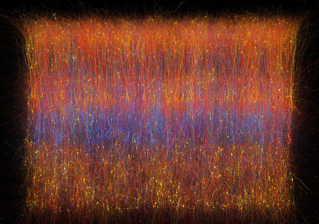
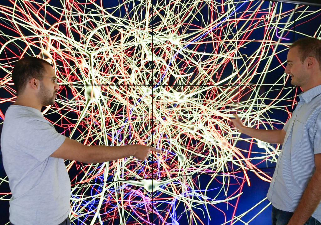
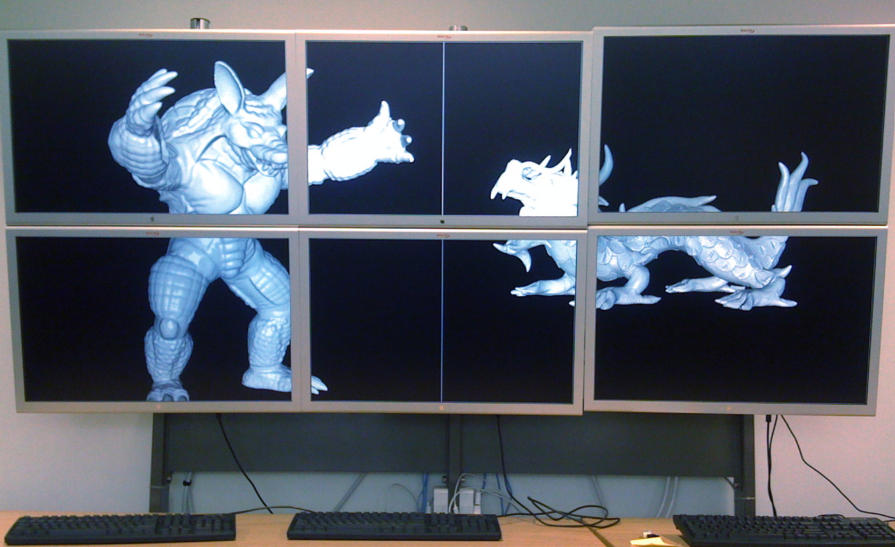
After decades of exponential growth in computational performance, storage and data acquisition, computing is now well in the big data age, where future advances are measured in our capability to extract meaningful information from the available data. Visual analysis based on the interactive rendering of three-dimensional data has been proven to be a particularly efficient approach to gain intuitive insight into spatial structures and the relations of very large 3D data sets. For example, the electrical slice simulation in Figure 1.1 (top left) contains millions of voltage samples per time step. A visualisation makes this electrical activity immediately understandable, and highlights eventual anomalies in the simulation. These developments create new, unique challenges for applications and system software to enable users to fully exploit the available resources to gain insight from their data.
The quantity of computed, measured or collected data is growing exponentially, fuelled by the pervasive diffusion of digitalisation in modern life. Moreover, the fields of science, engineering and technology are increasingly defined by a data-driven approach to research and development. High-quality and large-scale data is continuously generated at a growing rate from sensor and scanning systems, as well as from data collections and numerical simulations in a number of science and technology domains.
Display technology has made significant progress in the last decade: High-resolution screens and tiled display walls are now affordable for most organisations, and are getting deployed at an increasing rate. This increased resolution and display size helps with understanding the data through higher fidelity, but causes a quadratic increase in pixels to be rendered, which in turn challenges rendering algorithms to deliver an interactive frame rate. Such large-scale visualisation systems are often driven by multiple GPUs and workstations, making it natural, and most times necessary, to drive them using parallel and distributed applications.
However, not only applications are becoming more and more data-driven, but also the technology used to tackle these kinds of problems has been witnessing a paradigm shift towards massively parallel on-chip and distributed parallel cluster solutions. On one hand, parallelism within a system has increased massively, with tenths of CPU cores, thousands of GPU cores and multiple CPUs and GPUs in a single system. On the other hand, massively parallel distributed systems are easily accessible from various cloud infrastructure providers, and are also affordable for on-site hosting for many organisations.
System software to exploit the available hardware parallelism capable of performing efficient interactive data exploration has not kept up with the pace in hardware developments and data gathering capabilities. Mostly, this is due to an inherent delay between hardware and software capabilities, as development typically only starts once the hardware is available. Secondly, existing software is often engineered for different design parameters and has a significant inertia to change, to the extreme cost of having to rewrite it from scratch.
In the context of emerging data-intensive knowledge discovery and data analysis, efficient interactive data exploration methodologies have become critical. Visual analysis by means of interactive visualisation and inspection of three-dimensional data is a particularly efficient approach to gain intuitive insight into the spatial structure and relations of very large 3D data sets. However, defining visual and interactive methods scaling with problem size and the degree of parallelism, as well as generic applicability of high-performance interactive visualisation methods and systems, are recognised among the major current and future challenges.
1.2 Challenges
Increased display fidelity and faster rendering performance help to visualise large data sets efficiently. Parallel rendering is one approach to achieve this goal by using multiple GPUs, and often multiple computers, to improve the rendering performance. It creates a new set of research challenges, which can be broken down in more concrete challenges, starting with formalising and implementing the architecture of a parallel rendering framework.
These sub-challenges to build better scalable parallel rendering applications can be identified as finding better task decompositions, decreasing the cost for the result composition, reducing the latency of the overall system, and minimising synchronisation between the parallel execution threads.
Interactive visualisation poses its own unique set of challenges. The goal is to present a believable alternate universe to the visual system of the user. This process turns interactive visualisation into a powerful tool, by utilising the brains’ native capabilities to interpret and understand data. Virtual Reality (VR) takes this goal to the extreme, and when done right, makes the user forget that he interacts with a virtual world.
To achieve this goal, visualisation has the daunting task to transform large amount of data into coloured pixels in a short amount of time. Believable visualisation has to minimise the latency between user input and the resulting output, and to maximise the number of frames rendered per second. With increased immersion in the data, these parameters become more important – for Virtual Reality, a 60 Hz refresh rate and a latency below 50 ms is required, whereas for non-immersive desktop visualisation 10 Hz and 200 ms are acceptable.
When starting from a given rendering problem, the first task of a parallel rendering system is to decompose (parallelise) this task into independent sub-tasks, each rendered by a separate resource in parallel. While the basics of this decomposition have been researched extensively, there are architectural challenges to make these decompositions easily available in a generic and structured manner. Load balancing these tasks for an optimal parallelisation present many still unaddressed challenges for modern visualisation cluster sizes, consisting of tens to hundreds of GPUs, and increasingly affordable high-fidelity visualisation systems with tens of displays and hundreds of millions of pixels.
By scaling up the amount of resources employed to accelerate the rendering task, the task of combining the partial results from each resource becomes more challenging. For some decomposition algorithms, the amount of data to composite grows linearly with the amount of parallel resources used, and keeping the compositing time within the available budget is a non-trivial problem.
For parallel rendering, these constraints make building a parallel and distributed application harder compared to other distributed applications for simulations and cloud computing. In particular, one has to be careful with synchronisation and pipelining of operations to minimise latency. In addition, an interactive application has different requirements when it comes to resource allocation compared to other large-scale distributed computing domains.
Last, but not least, a significant challenge is how to make all this research available to the large data scientists with the actual needs and use cases for parallel rendering.
1.3 Parallel Rendering
Parallel rendering utilises multiple rendering units (GPUs), often on different computers, to generate images for one or more output displays. Scalable rendering is the subset of parallel rendering which uses multiple resources to accelerate the rendering of one or more outputs. The goal of parallel rendering is to increase the output resolution, rendering performance or rendering quality. Traditionally the focus has been on the first two goals, often in isolation of each other, e.g., algorithms and implementations for Cave systems tend to be different from scalable rendering for large data visualisation.
The main performance indicator for Large Data Interactive Rendering is the performance of the rendering algorithm, that is, the framerate with which the program produces new images. This framerate can be improved by either using faster or more hardware, or by better algorithms exploiting existing hardware and data. This thesis primarily focuses on the first approach, using parallel rendering to exploit the CPU and GPU parallelism available on a single system, or a distributed cluster. The early fundamental concepts have been laid out in [Molnar et al., 1994] and [Crockett, 1997] (Figure 1.2). A number of domain specific parallel rendering algorithms and special purpose hardware solutions have been proposed in the past, however, only few generic parallel rendering frameworks have been developed.
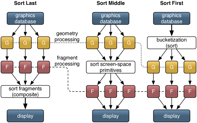
Sort-last rendering decomposes the rendering task in data space, that is, each resource renders a part of the data. In the end partial fragments from each resource are composited into a final result image. Sort-middle rendering also decomposes the rendering at the data level, but collects and sorts the unshaded primitives before or after rasterisation, and then performs the fragment shading on the sorted data. Sort-first rendering decomposes the rendering task in screen space, and the application needs either to be fill-rate bound or have efficient view frustum culling to scale the rendering performance. We will focus on sort-last and sort-first rendering, since sort-middle architectures are only feasible in a hardware implementation due to the large amount of data processed and transferred in the sorting stage.
1.3.1 Domain Specific Solutions
Cluster-based parallel rendering has been commercialised for off-line rendering (i.e. distributed ray-tracing) for computer generated animated films or special effects, since the typically used ray-tracing technique is inherently amenable to parallelisation for off-line processing. Other special purpose solutions exist for parallel rendering in specific application domains such as volume rendering [Li et al., 1997, Wittenbrink, 1998, Huang et al., 2000, Schulze and Lang, 2002, Garcia and Shen, 2002, Nie et al., 2005] or geo-visualisation [Vezina and Robertson, 1991, Agranov and Gotsman, 1995, Li et al., 1996, Johnson et al., 2006]. However, such specific solutions are typically not applicable as a generic parallel rendering paradigm and do not translate to arbitrary scientific visualisation and distributed graphics problems.
In [Niski and Cohen, 2007] parallel rendering of hierarchical level-of-detail (LOD) data has been addressed and a solution specific to sort-first tile-based parallel rendering has been presented. While the presented approach is not a generic parallel rendering system, basic concepts presented in [Niski and Cohen, 2007], such as load management and adaptive LOD data traversal, can be carried over to other sort-first parallel rendering solutions.
1.3.2 Special Purpose Architectures
Historically, high-performance real-time rendering systems have relied on an integrated proprietary system architecture, such as the early SGI graphics supercomputers. Special purpose solutions have become a niche product as their graphics performance did not keep up with off-the-shelf workstation graphics hardware and scalability of clusters.
Due to its conceptual simplicity, a number of special purpose image compositing hardware solutions for sort-first parallel rendering have been developed. The proposed hardware architectures include Sepia [Moll et al., 1999, Lever, 2004], Sepia 2 [Lombeyda et al., 2001a, Lombeyda et al., 2001b], Lightning 2 [Stoll et al., 2001], Metabuffer [Blanke et al., 2000, Zhang et al., 2001], MPC Compositor [Muraki et al., 2001] and PixelFlow [Molnar et al., 1992, Eyles et al., 1997], of which only a few have reached the commercial product stage (i.e. Sepia 2 and MPC Compositor). However, the inherent inflexibility and setup overhead have limited their distribution and application support. Moreover, with the recent advances in the speed of CPU-GPU and GPU-GPU interfaces, such as PCI Express, NVLink and other modern interconnects, combinations of software and GPU-based solutions offer more flexibility at a comparable performance.
1.3.3 Generic Approaches
A number of algorithms and systems for parallel rendering have been developed in the past. Some general concepts applicable to cluster parallel rendering have been presented in [Mueller, 1995, Mueller, 1997] (sort-first architecture), [Samanta et al., 1999, Samanta et al., 2000] (load balancing), [Samanta et al., 2001] (data replication), or [Cavin et al., 2005, Cavin and Mion, 2006] (scalability). On the other hand, specific algorithms have been developed for cluster based rendering and compositing such as [Ahrens and Painter, 1998], [Correa et al., 2002] and [Yang et al., 2001, Stompel et al., 2003]. However, these approaches do not constitute APIs and libraries that can be readily integrated into existing visualisation applications, although the issue of the design of a parallel graphics interface has been addressed in [Igehy et al., 1998].
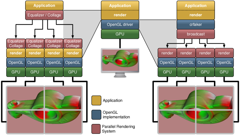
Only few generic APIs and (cluster-)parallel rendering systems exist, including VR Juggler [Bierbaum et al., 2001] (and its derivatives), Chromium [Humphreys et al., 2002] (an evolution of [Humphreys and Hanrahan, 1999, Humphreys et al., 2000, Humphreys et al., 2001]), ClusterGL [Neal et al., 2011] and OpenGL Multipipe SDK [Jones et al., 2004, Bhaniramka et al., 2005, MPK, 2005]. These approaches can be categorised into transparent interception and distribution of the OpenGL command stream and into the parallelisation of the application rendering code (Figure 1.3).
VRJuggler
VR Juggler [Bierbaum et al., 2001, Just et al., 1998] is a graphics framework for virtual reality applications, shielding the application developer from the underlying hardware architecture, devices and operating system. Its main aim is ease of use in virtual reality configurations and use, without the need to know about the devices and hardware configuration details, but not specifically to provide scalable rendering. Extensions of VR Juggler, such as for example ClusterJuggler [Bierbaum and Cruz-Neira, 2003] and NetJuggler [Allard et al., 2002], are typically based on the replication of application and data on each cluster node and only take care of synchronisation issues, but fail to provide a flexible and powerful configuration mechanism that efficiently supports scalable rendering as also noted in [Staadt et al., 2003]. VR Juggler does not support scalable parallel rendering such as sort-first and sort-last task decomposition and image compositing, nor does it provide other important features for parallel rendering, such as network swap barriers (synchronisation), distributed objects, image compression and transmission, or multiple rendering threads per process.
Chromium
Chromium [Humphreys et al., 2002] provides a powerful and transparent abstraction of the OpenGL API allowing a flexible configuration of display resources. It is limited in scalability, due to its focus on streaming OpenGL commands through a network of nodes, often initiated from a single source. This has also been observed in [Staadt et al., 2003], and is caused by the size of the OpenGL stream. This data stream not only contains OpenGL calls, but also geometry and image data. Only if the geometry and textures are mostly static and can be kept in GPU memory on the graphic card, no significant bottleneck can be expected, as the OpenGL stream is then composed of a relatively small number of rendering instructions. For typical real-world visualisation applications, display and object settings are interactively manipulated, data and parameters may change dynamically, and large data sets do not fit statically in GPU memory, but are often dynamically loaded from out-of-core and/or multi-resolution data structures. This can lead to frequent updates not only of commands and parameters which have to be distributed, but also of the rendered data itself (geometry and texture), thus causing the OpenGL stream to expand dramatically. Furthermore, this stream of function calls and data must be packaged and broadcast in real-time over the network to multiple nodes for each rendered frame. This makes CPU performance and network bandwidth more likely the limiting factor.
The performance experiments in [Humphreys et al., 2002] indicate that Chromium is working well when the rendering problem is fill-rate limited. This is due to the fact that the OpenGL commands and a non-critical amount of rendering data can be distributed to multiple nodes without significant problems. The critical fill-rate work is then performed locally on the graphics hardware.
Chromium also provides some facilities for parallel application development: A sort-last, binary-swap compositing stream processing unit and an OpenGL extension providing synchronisation primitives, such as a barrier and semaphore. It leaves problems like configuration, task decomposition, process and thread management unaddressed. Parallel Chromium applications tend to be written for one specific parallel rendering use case and configuration, e.g. the sort-first distributed memory volume renderer in [Bethel et al., 2003], or the sort-last parallel volume renderer raptor [Houston, 2005]. We are not aware of a generic Chromium-based application using many-to-one sort-first or stereo decompositions.
The concept of transparent OpenGL interception popularised by WireGL and Chromium has received further contributions. While some commercial implementations such as TechViz and MechDyne Conduit continue to exist, on the research side only ClusterGL [Neal et al., 2011] has been presented recently. ClusterGL employs the same approach as Chromium, but delivers a significantly faster implementation of transparent OpenGL interception and distribution for parallel rendering. Transparent OpenGL interception is an appealing approach for some applications, as it requires no code changes. It has inherent limitations due to the fact that eventually the bottleneck becomes the single-threaded application rendering code, the amount of application data the single application instance can load or process, or the the size of the OpenGL command stream sent over the network.
CGLX
CGLX [Doerr and Kuester, 2011] aims to bring parallel execution transparently to OpenGL applications, by emulating the GLUT API and intercepting certain OpenGL calls. Its target use case are multi-display installations, i.e., static sort-first rendering with no compositing. In contrast to frameworks like Chromium and ClusterGL, which distribute OpenGL calls, CGLX follows the distributed application approach. This works transparently for trivial applications, but quickly requires the application developer to address the complexities of a distributed application, when mutable application state needs to be synchronised across processes. For production applications, writing parallel applications remains the only viable approach for scalable rendering, as shown by the success of Paraview, Visit and Equalizer-based applications.
OpenGL Multipipe SDK
OpenGL Multipipe SDK (MPK) [Bhaniramka et al., 2005] implemented an effective parallel rendering API for a shared memory multi-CPU/GPU system. It is similar to IRIS Performer [Rohlf and Helman, 1994] in that it handles multi-GPU rendering by a lean abstraction layer via a callback mechanism, and that it runs different application tasks in parallel. However, MPK is not designed nor meant for rendering nodes separated by a network. MPK focuses on providing a parallel rendering framework for a single application, parts of which are run in parallel on multiple rendering channels, such as the culling, rendering and final image compositing processes. The author used to be the technical lead developer of OpenGL Multipipe SDK, therefore Equalizer is in many ways an evolution of MPK for distributed execution, improved performance and better configurability.
Tiled Display Walls
Software for driving and interacting with tiled display walls has received significant attention, in particular Sage [Renambot et al., 2004] and Sage 2 [Marrinan et al., 2014]. Sage was built entirely around the concept of a shared framebuffer where all content windows are separate applications using pixel streaming. It is no longer actively supported. Sage 2 is a complete, browser-centric reimplementation where each application is a web application distributed across browser instances. DisplayCluster [Johnson et al., 2012], and its continuation Tide [Blue Brain Project, 2016], also implement the shared framebuffer concept of Sage, but provide a few native content applications integrated into the display servers. These solutions implement a scalable display environment and are a target display platform for scalable 3D graphics applications.
1.4 Thesis Structure
In the next chapter, we give a summary of the contributions of this thesis, listing relevant publications and the contributions of the author to these publications. Chapter 3 introduces the architecture of a parallel rendering framework, the foundation for this thesis. Chapter 4 presents new algorithms for the task decomposition in parallel rendering. Chapter 5 focuses on optimisations to reduce the cost of recombining the results of a parallel rendering decomposition. Chapter 6 describes better approaches to balance the task assignment to rendering resources. Chapter 7 describes the design and architecture of a network library tailored to parallel rendering. Before a conclusion in Chapter 9, Chapter 8 provides an overview of the major Equalizer applications.
Chapter 2 Contributions
This chapter summarises the main contributions of this thesis. In each section, we list the relevant publications and specify the contributions of the author.
2.1 Parallel Rendering Architecture
A major contribution of this thesis is the formalisation of the architecture for a parallel rendering framework and its reference implementation, which advances the state of the art in many aspects:
- Minimally invasive API:
-
The guiding principle for the API design was to allow applications to retain all their rendering code and application logic. The programming interface is based on a set of C++ classes, modelled closely to the resource hierarchy of a graphics rendering system. The application subclasses these objects and overrides C++ task methods, similar to C callbacks. These task methods will be called in parallel by the framework, depending on the current configuration. The contract for the implementation of the task methods does not assume any specific rendering library, algorithm or technology, thus facilitating the adaptation of existing applications for parallel rendering. This parallel rendering interface is significantly different from Chromium [Humphreys et al., 2002] and more similar to VRJuggler [Bierbaum et al., 2001] and MPK [Bhaniramka et al., 2005].
- Runtime configuration:
-
The architecture of our parallel rendering framework makes a clear separation between the rendering algorithm and the runtime configuration. It provides a contract between the framework and the application code based on a rendering context, and uses this context to drive the application output depending on the runtime configuration. Application developers are unaware of parallel rendering setups and make no assumptions on how the rendering code will be executed. This clear separation yields parallel rendering applications which can be deployed on a wide set of installations, and are often configured in new ways unforeseen during their deployment.
- Display abstraction:
-
Large scale visualisation systems cover a wide set of use cases from classical workstation setup to monoscopic tiled display walls, stereoscopic, edge-blended multi-projector walls to fully immersive installations CAVE systems. Consequently, applications running on these systems serve many different use cases. Our novel canvas-layout abstraction provides a simple configuration for all these installations and empowers applications using these installations with 2D and 3D contextual information, runtime stereo configuration, and head tracking.
- Compound trees:
-
The introduction of compounds, and their underlying contract, provides a formalisation of a flexible task decomposition and result recomposition for parallel rendering. Compound trees allow for easy specification of complex parallel task decomposition strategies, which are implemented and executed by the Equalizer system. They generalise parallel rendering principles without hardcoding a specific parallel rendering algorithm, thus proposing an orthogonal parameter set for decomposing rendering tasks, assembling results, and adapting these parameters at runtime. Furthermore, they facilitate new parallel rendering research due to their flexibility and extensibility.
- Equalizers:
-
The namesake of our framework, they are active components hooked into a compound tree, and modify compound tree parameters at runtime. For example, a sort-first load balancer adapts the sub-viewports assigned to each resource at runtime. Compounds are the passive configuration, and equalizers are the active component to optimize this configuration dynamically. This makes their implementation independent of the rest of the framework, providing a powerful abstraction for research and development of better resource usage for parallel rendering.
- Modular architecture:
-
Our architecture uses layered abstractions that gradually provide higher level abstractions. On the lower level, a network library for distributed abstractions provides the substrate for Equalizer and its applications. Within each library, a clear separation of responsibilities allows an easy combination of existing algorithms. For example, an advanced feature like a cross-segment equalizer relies on per-segment load equalizers, and both equalizers reconfigure the underlying compound tree each frame.
[Eilemann et al., 2009] and [Eilemann et al., 2018] publish the architectural foundations of parallel rendering frameworks. Any algorithmic implementation and architectural contributions in these publications are contributed by the author, while experimental results have significant contributions from the secondary authors.
[Bhaniramka et al., 2005] provides in many ways the foundation for Equalizer, to which the author was a contributor for the implementation of a parallel rendering framework for shared memory systems.
2.2 Scalable Rendering and Compositing
Based on the flexible system architecture we implemented new scalable rendering algorithms, introduced in [Eilemann et al., 2009] and [Eilemann et al., 2018]. A particular focus was given on reducing cost for the expensive compositing step of sort-last rendering.
[Eilemann and Pajarola, 2007] provides an analysis of parallel compositing algorithms in an early version of our parallel rendering framework, and we show that direct send compositing has advantages on commodity visualisation clusters. The implementation, algorithm and experimental analysis in this paper are contributed by the author.
[Makhinya et al., 2010] introduced more sort-last compositing optimisations, most notably automatic region-of-interest detection and new compression algorithms. The author contributed the foundations for using region of interest, and the fast RLE compression with optimised data preconditioning.
[Eilemann et al., 2012] introduces many algorithmic optimisations for modern visualisation clusters, ranging from asynchronous compositing, thread and memory placement on NUMA architectures, region of interest, and an analysis of real-world application performance. We show that careful system design and detailed optimisations are necessary to achieve scalability on larger visualisation clusters. For this publication, the author contributed the algorithms, large parts of the implementation in Equalizer, and some experimental analysis.
2.3 Load Balancing
Optimal resource usage in larger visualisation clusters relies on an even distribution of work over the available resources. This load balancing problem requires real-time algorithms based on imperfect knowledge of the system and application behaviour. In our architecture, load balancing is achieved by modifying the compound tree parameters at runtime. For example, a sort-first load balancer adapts the sub-viewports assigned to each resource at runtime. These so-called equalizers are a component hooked into the compound tree, which makes their use and implementation independent of the rest of the framework.
[Eilemann et al., 2009] and [Eilemann et al., 2018] provide experimental results on the effectiveness of our sort-first and sort-last load balancing implementations. In the latter publication, we compare two different reactive load balancing algorithms and show that the theoretically superior algorithms do not necessarily provide better performance in realistic scenarios.
[Erol et al., 2011] introduces a novel algorithm for load balancing an arbitrary set of rendering resources to drive visualisation installations with many output displays, like tiled display walls or multi-projector systems. The author contributed the algorithm and implementation for this publication.
[Steiner et al., 2016] provides an implementation and detailed analysis of central task queueing with work packages and different task affinity modes for sort-first and sort-last rendering. The author provided the base queueing infrastructure for this publication.
Chapter 3 Parallel Rendering Architecture
3.1 Overview
A generic parallel rendering framework has to cover a wide range of use cases, target systems, and configurations. This requires a strong separation between the implementation of the application and its configuration, linked with a careful design to allow the resulting program to scale up to hundreds of nodes, while providing a minimally invasive API for the developer. In this section we present the system architecture of the Equalizer parallel rendering framework, and motivate its design in contrast to related work.
The motivation to use parallel rendering is either driven by the need to drive multiple displays or projectors from multiple GPUs and potentially multiple nodes, or by the need to increase rendering performance to visualise more data, or use a more demanding rendering algorithm for higher visual quality. Occasionally both needs coincide, e.g., for the analysis for large data sets on high fidelity visualisation systems.
Parallel rendering has similarities to other distributed computing domains like cloud computing and high-performance computing (HPC). It aims to accelerate the completion of a task by parallelising a time-consuming algorithm, or to allow the computation of a larger problem by employing multiple resources. Certain aspects are shared across these distributed computing domains, such as the need to load balance the parallel task execution, minimise synchronisation and communication overhead, as well as to find a task decomposition which allows to produce correct results.
Parallel rendering has one significant additional constraint: serving an interactive use case. Depending on the application domain and visualisation system, typically a framerate between 10 Hz and 120 Hz is required for useful user interaction. In turn, this translates to a budget of 8 ms to 100 ms to decompose the task to render a frame, perform parallel rendering, and to composite and display the result. In comparison, cloud computing and HPC typically have turnaround times of seconds to hours. Therefore, many algorithms for parallel rendering compute a suboptimal solution, but do so in at most a few milliseconds.
Fundamentally two approaches enable applications to use multiple GPUs: transparent interception at the graphics API (typically OpenGL), or extending the application to support parallel rendering natively (Figure 1.3). The first approach has been extensively explored by Chromium and others, while the second is the foundation for this thesis. The architecture of Equalizer is founded on an in-depth requirements analysis of typical visualisation applications, existing frameworks, and previous work on OpenGL Multipipe SDK.
The task of parallelising a visualisation application boils down to configuring the applications’ rendering code differently for each resource, enabling this rendering code to access the correct data, and synchronising execution. For scalable rendering, when multiple GPUs are used to accelerate a single output, partial results need to be collected from all contributing resources, combined, and send to the output.
The architecture of our parallel rendering framework addresses the following research questions:
-
•
How can we reduce end-to-end system latency for better user experience?
-
•
In a generic parallel rendering framework, how can we schedule the different rendering stages to minimise the latency for the user?
-
•
How can we architect the parallel rendering framework to minimise synchronisation between threads?
Section 3.2 introduces our asynchronous execution model, which has been carefully designed to minimise synchronisation points, maximise pipelining and enables early display of rendered images.
-
•
How can we maximise the impact of this research on large data scientists?
Ultimately, accessible applications determine the impact for large data research. With Equalizer we provide the base building blocks: a minimally invasive API and distributed execution layer to lower the entry barrier for application developers, a flexible configuration with a clear separation from the implementation, comprehensive VR features and tiled display wall integration addressing a wide set of visualisation installations. Various applications, introduced in Chapter 8, have been developed using Equalizer.
In this chapter, we will first describe the execution model and resource configuration, followed by how the generic configuration is used to model the desired visualisation setup, and finally introduce specifics of scalable and distributed rendering.
3.2 Asynchronous Execution Model
The core execution model for parallel rendering was pioneered by CAVELib [DeFanti et al., 1998], refined by OpenGL Multipipe SDK for shared memory systems and scalable rendering, and substantially extended by Equalizer for asynchronous and distributed execution. By analysing the typical architecture of a visualisation application we observe an initialization phase, a main rendering loop, and an exit phase. Equalizer decomposes these steps for parallel execution.
The main rendering loop typically consists of four phases: submitting the rendering commands to the graphics subsystem, displaying the rendered image, retrieving events from the operating system, and updating the application state before a new image is rendered. Usually, the configuration of the rendering is largely hard-coded, with a few configurable parameters such as field of view or stereo separation. For parallel execution, we need to separate the rendering code from this main loop, and execute it in parallel with different rendering parameters, as shown in Figure 3.1. Similarly, the initialisation and exit phase also need to be decomposed to allow managing of multiple distributed resources.
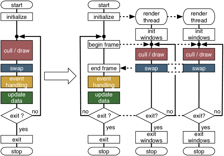
Figure 3.2 shows the execution of the rendering tasks of a two-node sort-first compound without latency and with a latency of one frame. The asynchronous execution pipelines rendering operations and hides imbalances in the load distribution, resulting in an improved framerate. We have observed a speedup of 15% on a five-node rendering cluster when using a latency of one frame instead of no latency in a sort-first configuration.
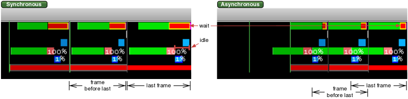
Another critical design parameter are synchronisation points. Most implementations, including OpenGL Multipipe SDK, use a per-frame barrier or similar synchronisation to manage parallel execution. In larger installations, this is detrimental to scalability, as even slight load imbalances limit parallel speedup. The Equalizer execution model is fully asynchronous, and only introduces synchronisation points when strictly required. The main synchronisation points are: configured swap barriers between a set of output channels which have to display simultaneously, the availability of input frames for scalable rendering, and a task synchronisation to prevent runaway of the main loop execution. By default, Equalizer keeps up to one frame of latency in execution, that is, some resources might render the next frame while others are still finishing the current frame. Nonetheless, finished resources will immediately display their result. This asynchronous execution architecture, coupled with a frame of latency, allows pipelining of many operations, such as the application event processing, task computation and load balancing, rendering, image readback, compression, network transmission, and compositing. It also hides small imbalances in the task distribution, as they usually average out over multiple frames.
In practical scenarios, application initialisation and exit is also a factor for usability. Consequently, these phases are also parallelised in Equalizer. A first pass identifies the resources to be launched or terminated, kicks off the tasks, and then uses a second pass to synchronize their execution and results.
benchmarkO.618
![[Uncaptioned image]](/html/1902.08755/assets/x6.png) Parallel Application Startup
Parallel Application Startup
Benchmark 3.2 shows the startup time of eqPly, our parallel polygon renderer. This benchmarks simply measures the time taken by Config::init, which includes the render client process creation using ssh from the application node, library loading from a shared filesystem, network setup, OpenGL and window initialisation, and object data mapping for the Equalizer resource instances and a few internal objects used by eqPly. The benchmark confirms that the application launch is scaling nicely to a medium cluster size. A slight increase in startup time with larger configurations is expected, since more processes increase the load on the shared filesystem and worsen distribution and synchronisation overheads. Due to the shared filesystem used for the executable, the startup times observe a large uncertainty, shown by the standard deviation bars.
benchmarkO.618
![[Uncaptioned image]](/html/1902.08755/assets/x7.png) Driving a Tiled Display Wall
Driving a Tiled Display Wall
In comparison to interception approaches as used by Chromium, our asynchronous programming model inherently provides better performance. Benchmark 3.2 tests the rendering performance for driving a simple tiled display wall configuration with a static model, rotating about its vertical axis, placed such that it nicely covers the different screens.
A standard tile-sort Chromium configuration is comparable to a simple Equalizer display wall setup, where in each case a single GPU and node is responsible for driving the attached display. The polygonal model is rendered using eqPly and uses display lists for the static geometry. Using display lists allows Chromium to send geometry and texture data only once to the rendering nodes (retained mode rendering) and display them repeatedly using glCallLists(), which is inexpensive in terms of network overhead. This setup is favourable for Chromium, because the display lists are transmitted only once over the network, and only simple display calls will be processed and distributed by Chromium for each rendered frame.
Chromium initially increases performance when adding nodes, but it quickly stagnates, and even decreases, when more nodes are added. In contrast, Equalizer continually improves performance with more added nodes and exhibits a smooth drop-off in speed-up, due to the expected synchronisation and network overhead as the rendered data gets negligible in size per node. This performance difference is also due to the fact that Equalizer can benefit from distributed parallel view frustum culling on each render thread.
3.2.1 Programming Interface
figureO.618
![[Uncaptioned image]](/html/1902.08755/assets/x8.png) Parallel Rendering Entities
Parallel Rendering Entities
Equalizer is a framework to facilitate the development of distributed and multi-threaded parallel rendering applications. The programming interface is based on a set of C++ classes, modelled closely to the resource hierarchy of a graphics rendering system. The application subclasses these objects and overrides C++ task methods, similar to C callbacks. These task methods will be called in parallel by the framework, depending on the current configuration. This parallel rendering interface is significantly different from Chromium [Humphreys et al., 2002] and more similar to VRJuggler [Bierbaum et al., 2001] and OpenGL Multipipe SDK [Bhaniramka et al., 2005].
To separate the responsibilities in a parallel rendering application, different entities are responsible for different aspects of the runtime system: the application process driving a rendering session, the server controlling the parallel rendering configuration, render clients executing the rendering tasks, and an administrative API to reconfigure the rendering session at runtime. All processes communicate with each other through a common network library (Collage) and a client library implementing the Equalizer API, as shown in Figure 3.2.1.
The administrative API connects to a server, and allows some changes to the running configuration,, e.g., to create new output channels. Its description is outside of the scope of this thesis, and is mentioned here for completeness.
3.2.2 Application
The main application thread in Equalizer drives the rendering, that is, it carries out the main event loop, but does not actually execute any rendering. Depending on the configuration, the application process often hosts one or more render client threads. These application render threads are identical in behaviour and implementation to render threads on the render client nodes. When a configuration has no additional nodes besides the application node, we have a single-process, multi-threaded rendering application: all application code is executed in the same process, and no network data distribution has to be implemented.
The main rendering loop is simple: The application requests a new frame to be rendered, synchronises on the completion of a frame and processes events received from the render clients. It may perform idle processing between the start and synchronisation of a frame. Figure 3.1 shows a simplified execution model of an Equalizer application.
3.2.3 Server
The Equalizer server manages the parallel rendering session. It is an asynchronous execution thread or process, which receives requests from the application and serves these requests using the current configuration, launching and stopping rendering client processes on nodes, determining the rendering tasks for a frame, and synchronising the completion of tasks.
3.2.4 Render Client
During initialisation, the application provides a rendering client executable. The rendering client is often, especially for simple applications, the same executable as the application. However, in more sophisticated implementations, the rendering client can be another executable which only contains the application-specific rendering code. The server deploys this rendering client on all nodes specified in the configuration. Render clients may run on a different architecture or operating system from the main application, the underlying network library ensures type safety and endian ordering.
In contrast to the application process, the rendering client main loop is completely controlled by Equalizer, based on application commands. A render client consists of the following threads: The node main thread, one network receive thread, one thread for each graphic card (GPU) to execute rendering tasks, and optionally one thread for asynchronous readback per GPU. If a configuration also uses the application node for rendering, then the application process uses one or more render threads, consistent with render client processes. The Equalizer client library implements the main loop, which receives network commands, processes them, and invokes the necessary task methods provided by the developer.
The task methods clear the frame buffer as necessary, execute the OpenGL rendering commands as well as readback, and assemble partial frame results for scalable rendering. All tasks have default implementations so that only the application specific methods have to be implemented, which at least involves the frameDraw() method executing a rendering task. For example, the default callbacks for frame recomposition during scalable rendering implement tile-based assembly for sort-first and stereo decompositions, and unordered -buffer compositing for sort-last rendering.
Render Context
The render context is the core entity abstracting the application-specific rendering algorithm from the system-specific configuration. It specifies:
- Buffer
-
OpenGL-style read and draw buffer as well as colour mask. These parameters are influenced by the current eye pass, eye separation and anaglyphic stereo settings.
- Viewport
-
Two-dimensional pixel viewport restricting the rendering area. The pixel viewport is influenced by the destination viewport definition and viewports set for sort-first decompositions.
- Frustum
-
Frustum parameters as defined by glFrustum. Typically the frustum is used to set up the OpenGL projection matrix. The frustum is influenced by the destinations view definition, sort-first decomposition, tracking head matrix and the current eye pass.
- Head Transformation
-
A transformation matrix positioning the frustum. For planar views this is an identity matrix and is used in immersive rendering. It is usually used to set up the ‘view’ part of the modelview matrix, before static light sources are defined.
- Range
-
A one-dimensional range within the interval [0..1]. This parameter is optional and should be used by the application to render only the appropriate subset of its data for sort-last rendering.
- View
-
The view object from the logical rendering rendering configuration, as introduced below. Holds view-specific data, such as camera, model or any other application state.
Event Handling
Event handling routes events from the source window in the rendering thread to the application main thread for consumption. At each step, events can be observed, transformed or dropped. Events are received from the operating system in the rendering thread, transformed there into a generic representation, and sent to the application main thread. The application processes them in the main loop and modifies its internal state accordingly. This follows the natural data flow for most windowing systems and has natural semantics for thread safe event handling. For Qt, Equalizer internally dispatches events from the process main thread to the render threads to ensure consistent behaviour.
3.2.5 NUMA Aware Thread Scheduling
Non-Unified Memory Access (NUMA) is a common hardware architecture for high-performance visualisation clusters. Modern multi-socket render nodes use a NUMA architecture, where each CPU socket has a number of locally-attached memory buses, GPU and network devices, and CPU sockets are linked with an interconnect to each other. Accessing a memory address located on another processor has a performance penalty for both bandwidth and latency, and accessing a GPU or network interface from a remote processor is slower than a local access.
figureO.618
![[Uncaptioned image]](/html/1902.08755/assets/x9.png) Exemplary Dual-Socket NUMA Node
Exemplary Dual-Socket NUMA Node
Figure 3.2.5 shows one such NUMA visualisation node, used in the experiments of [Eilemann et al., 2012]. It has two CPU sockets with six cores each, three GPUs connected to the two sockets, and two network cards (10 Gigabit Ethernet and InfiniBand) connected to one socket.
In our parallel rendering system, a number of threads are used to drive a single process in the cluster: the main thread (main), one rendering thread for each GPU (draw) and one thread to finish asynchronous downloads (read), one thread for receiving network data (recv), one command processing thread (cmd), and one thread for image transmission to other nodes (xmit). We have implemented automatic thread placement by extending and using the hwloc library in Equalizer. We restrict all node threads (main, recv, cmd, xmit) to the cores of the processor local to the network card, and all GPU threads (draw, read) to the cores of the processor closest to the respective GPU.
figureO.618
![[Uncaptioned image]](/html/1902.08755/assets/x10.png) Thread Placement on a NUMA Node
Thread Placement on a NUMA Node
Figure 3.2.5 shows the thread placement for the node used in Figure 3.2.5. Threads are bound to all cores of the respective socket, and the ratio of cores to threads varies with the used hardware and software configuration. Many of the threads do not occupy a full core at runtime, especially node threads are mostly idle on a rendering client.
When using the default first-touch memory placement strategy, memory is allocated on the processor where it is first accessed. All GPU-specific memory allocations are done by the render threads executing the rendering code, therefore placing the CPU-side buffers onto the same socket as the corresponding GPU. Similarly, network buffers are allocated and used from the one of the node threads.
benchmarkO.618
![[Uncaptioned image]](/html/1902.08755/assets/x11.png) Thread Affinity on NUMA Hardware
Thread Affinity on NUMA Hardware
We tested the influence of thread placement by explicitly placing the threads either on the correct or incorrect processor. A low-level memory bandwidth test shows a performance difference between these two settings. We found that this leads to a performance improvement of more than 6% in real-world rendering loads, as shown in Benchmark 3.2.5. This benchmark uses the aforementioned cluster nodes, and renders polygonal data using sort-first scalable rendering. The exact experiment setup is described in [Eilemann et al., 2012]. While this is a relatively small influence, it becomes more important with higher frame rates as the relative draw time decreases, and the memory-intensive compositing step importance increases. Thread placement is therefore one of the components to achieve scalability on larger visualisation clusters with NUMA nodes.
3.3 Configuration
A configuration consists of the declaration of the rendering resources, the physical and logical description of the projection system, and the configuration on how the aforementioned resources are used for parallel and scalable rendering. A configuration is an instantiated class hierarchy in memory used by the server to compute rendering tasks, and has a serialised text file format to read and write configuration files.
The rendering resources are represented in a hierarchical tree structure which corresponds to the physical and logical resources found in a 3D rendering environment: nodes (computers), pipes (graphic cards), windows, and channels (2D rendering area in a window).
Physical layouts of display systems are configured using canvases with segments, which represent 2D rendering areas composed of multiple displays or projectors. Logical layouts are applied to canvases and define the views on a canvas. Observers observe multiple views and represent a head-tracked user in a visualisation application.
Scalable resource usage is configured using a compound tree, which is a hierarchical representation of the rendering decomposition and result recomposition across the resources.
3.3.1 Rendering Resources
The first part of the configuration is a hierarchical structure of node pipes windows channels describing the rendering resources. The developer will use instances of these classes to implement application logic and manage data.
The node is the representation of a single computer in a cluster. One operating system process of the render client executable will be used for each node. Each configuration might also use an application node, in which case the application process is also used for rendering.
The pipe is the abstraction of a graphics card (GPU), and uses an operating system thread for rendering. All pipe, window and channel task methods are executed from the pipe thread. The pipe maintains the information about the GPU to be used by the windows for rendering.
The window encapsulates a drawable and an OpenGL context. The drawable can be an on-screen window or an off-screen pbuffer or framebuffer object (FBO). Windows on the same pipe share their OpenGL rendering resources. They execute their rendering tasks sequentially on the pipe’s execution thread, in the order they are defined in the configuration.
The channel abstracts an OpenGL viewport within its parent window. It is the entity executing the actual rendering. The channel’s rendering context is overwritten when it is rendering for another channel during scalable rendering. Multiple channels in application windows may be used to view the model from different viewports. Sometimes, a single window is split across multiple projectors, e.g., by using an external splitter such as the Matrox TripleHead2Go.
3.3.2 Display Resources
Display resources are the second part of the configuration. They describe the physical display setup (canvases segments), logical display (layouts views) and head tracking of users within the visualisation installation (observers).
A canvas represents one physical projection surface, e.g., a PowerWall, a curved screen, an immersive installation, or a window on a workstation. Canvases provide a convenient way to configure projection surfaces. They group a set of segments (displays or projectors) into a 2D projection surface. A canvas uses layouts describing logical views. Typically, a desktop window uses one canvas, one segment, one layout and one view. One configuration might drive multiple canvases, for example a projection wall with an operator station. Planar surfaces, e.g., a display wall, configure a frustum for the respective canvas. For non-planar surfaces, the frustum will be configured on each display segment. The application rendering code has access to the 2D area being updated, for example to draw 2D menus on top of the 3D rendering.
figureO.618
![[Uncaptioned image]](/html/1902.08755/assets/x12.png) Wall and Projection Parameters
Wall and Projection Parameters
The frustum can be specified as a wall or projection description in the global reference system, which is shared with the head-tracking matrix of the application. A wall is defined by the bottom-left, bottom-right and top-left coordinates relative to the origin. A projection is defined by the position and head-pitch-roll orientation of the projector, as well as the horizontal and vertical field-of-view and distance to the projection wall. Figure 3.3.2 illustrates the wall and projection frustum parameters. All size units are in meters.
A canvas consists of one or more segments. A planar canvas typically has a frustum description, which initialises the segment frustum based on the 2D area covered by it. Non-planar frusta are configured by overriding the default segment frusta. These frusta typically describe a physically correct display setup for Virtual Reality installations.
A canvas has one or more layouts. One of the layouts is the active layout, that is, this set of views is currently used for rendering. It is possible to specify OFF as a layout, which deactivates the canvas. It is supported to use the same layout on different canvases, for example to mirror a display wall layout on a control station window.
A segment represents one output channel of the canvas, e.g., a projector or a display. A segment has an output channel, which references the channel to which the display device is connected. To synchronise the video output, a swap barrier is configured to synchronise the respective window buffer swaps. Swap barriers can use network-based software synchronisation or hardware synchronisation based on NVidia’s G-Sync hardware.
figureO.618
![[Uncaptioned image]](/html/1902.08755/assets/x13.png) A Canvas using four Segments
A Canvas using four Segments
A segment covers a two-dimensional region of its parent canvas, configured by the segment viewport. The viewport is in normalised coordinates relative to the canvas. Segments might overlap (edge-blended projectors) or have gaps between each other (display walls, Figure 3.3.2111Dataset courtesy of VolVis distribution of SUNY Stony Brook, NY, USA.). The viewport is used to configure the segment’s default frustum from the canvas frustum description, and to place logical views correctly.
A layout is the grouping of logical views. It is used by one or more canvases. For all given layout/canvas combinations, Equalizer creates destination channels when the configuration is loaded. These destination channels may later be referenced by compounds to configure scalable rendering. Layouts can be switched at runtime by the application. Switching a layout will activate different destination channels for rendering.
A view is a logical view of the application data, in the sense used by the Model-View-Controller pattern. It can configure a scene, viewing mode, viewing position, or any other representation of the application’s data. The view object is accessible to the application thread and all render threads contributing to its rendering. This allows the application to manage view-specific data by attaching it as a distributed object to the view, which will be synchronised from the application main thread to the render clients at the beginning of each frame.
A view has a fractional viewport relative to its layout. A layout is usually fully covered by its views. Each view can have a frustum description. The view’s logical frustum overrides physical frusta specified at the canvas or segment level. This is typically used for non-physically correct rendering, e.g., to compare two models side-by-side on a canvas. If the view does not specify a frustum, it will use the sub-frustum resulting from the covered area on the canvas. A view might reference an observer, in which case its frustum is head-tracked.
figureO.618
![[Uncaptioned image]](/html/1902.08755/assets/images/layout.png) Layout with four Views
Layout with four Views
Figure 3.3.2 shows an example layout using four views on a single segment. Figure 3.3 shows a real-world setup of a single canvas with six segments using underlap for the display bezels, with a two-view layout. This configuration generates eight destination channels.
An observer represents an actor looking at one or multiple views. It has a head matrix, defining its position and orientation within the world, eye offsets and focus distance parameters. Typically, a configuration has one observer. Configurations with multiple observers are used if multiple, head-tracked users are in the same configuration session, e.g., a non-tracked control host with two tracked head-mounted displays.
3.3.3 Compounds
Compound trees describe how multiple rendering resources are combined to produce the desired output, especially how multiple GPUs are aggregated to increase rendering performance. They are one of the core innovations, enabling a flexible resource configuration. Compounds are modified at runtime by equalizers to implement dynamic behaviour, e.g., for load balancing.
Compounds are a data structure to describe the execution of rendering tasks in the form of a tree. Each compound corresponds to some rendering tasks (clear, draw, assemble, readback) and references a channel from the resource description executing the tasks. The allocation of channels on pipes and nodes determines which resources execute the task, and what can be executed in parallel. A compound may provide output frames from the readback task to others, and can request input frames from others for its own assembly task. Output frames are linked to input frames by name.
Compound trees are a logical description of the rendering pipeline, and only reference the actual physical resources through their channels. This allows mapping a compound tree to different physical configurations by simply replacing the channel references. For example, one can test the functionality of a sort-last configuration by using channels of different windows on a single-GPU workstation before deploying it to multiple physical GPUs.
A simple leaf compound description for rendering a part of the data set, given by the data range, into a particular region of the viewport is shown in Figure 3.4. The data range is a logical mapping of the data set onto the unit interval and is left to the application to interpret appropriately. Hence, the range [0 ] indicates that the first half of the data set should be rendered, for example the first triangles of a polygonal mesh with faces. The viewport is indicated by the parameters [x y width height] as fraction of the parent’s viewport, and in the example the data is thus rendered into the left half of the viewport. The resulting framebuffer data – including per-pixel colour and depth – of the rendering executed on this channel is read back and is made available to other compounds by the name left_half.
| compound { | |
| channel ”draw” | |
| buffer [ COLOR DEPTH ] | |
| range [0 ] | |
| viewport [ 0 0 1 ] | |
| outputframe {name ”left_half” } | |
| } |
A non-leaf compound performing image assembly and compositing task is provided in Figure 3.5. Framebuffer data is read from two other compounds, which did execute rendering for part_a and part_b of the data set in parallel. The compound itself executes by default -depth visibility compositing of the two input images on its channel and returns the resulting colour framebuffer in the output frame named frame.display.
| compound { | |
| channel ”display” | |
| inputframe { name ”part_a” } | |
| inputframe { name ”part_b” } | |
| outputframe { buffer [ COLOR ] } | |
| } |
Leaf compounds execute all tasks by default, but the focus is often on the draw task with a default assemble and standard readback task used to pass the resulting image data on to other compounds for further compositing. While leaf compounds execute the rendering in parallel, non-leaf compounds often correspond to, but are not restricted to, the (parallel) image compositing and assembly part. The readback or assemble tasks are only active if output or input frames have been specified, respectively. Otherwise the rendered image frame is left in-place for further processing in a parent compound sharing the same channel.
Note that non-leaf nodes in the compound tree structure traverse their children first before performing their default assemble and readback tasks. Furthermore, compounds only define the logical task decomposition structure, while its execution is actually performed on the referenced channels. Therefore, since compounds can share channels, as often done between a parent and one of its child compounds, rendered image data can sometimes be left in place, avoiding readback and transfer to another node.
All attributes, as well as the channel, are inherited from the parent compound if not specified otherwise. The viewport, data range and eye attributes are used to describe the decomposition of the parents’ 2D viewport, database range, temporal, pixel, subpixel and eye passes, respectively.
A more formal classification of compound entities is:
- Root compound
-
is the top-level compound of a compound tree. It might also be a destination compound, or can be empty (not referencing a channel) when synchronising multiple destination channels.
- Destination compound(s)
-
are the top-most compounds referencing a channel, which becomes the destination channel. This destination channel determines the rendering context for the whole subtree, that is, compounds and their channels lower in the hierarchy contribute to the rendering of the destination channel by executing part of the destination render context and providing output frames which will eventually be composited onto the destination channel.
- Source compounds
-
are the leaf nodes in a compound tree. They typically use a different channel from the destination channel and configure scalability by overriding render context parameters. This decomposes the rendering of the destination channel. By adding output and input frames, the partial results are collected and composited:
- Decomposition
-
On each child compound the rendering task of that child can be limited by setting the viewport, range, period and phase, pixel, subpixel, eye or zoom as desired.
- Compositing
-
Source compounds define an output_frame to read back the result. This output frame is used as an input_frame on the destination compound receiving the pixels. The frames are connected with each other by their name, that has to be unique within the root compound tree. For parallel compositing, the algorithm is described by defining multiple input and output frames across all source compounds and restricting the task to assemble and readback.
- Intermediate compounds
-
may be used to simplify the task decomposition or to configure parallel compositing.
3.4 Virtual Reality
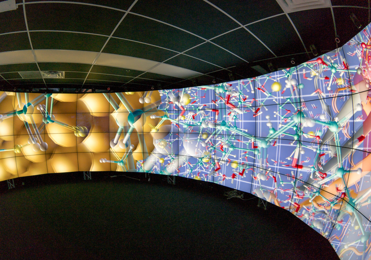
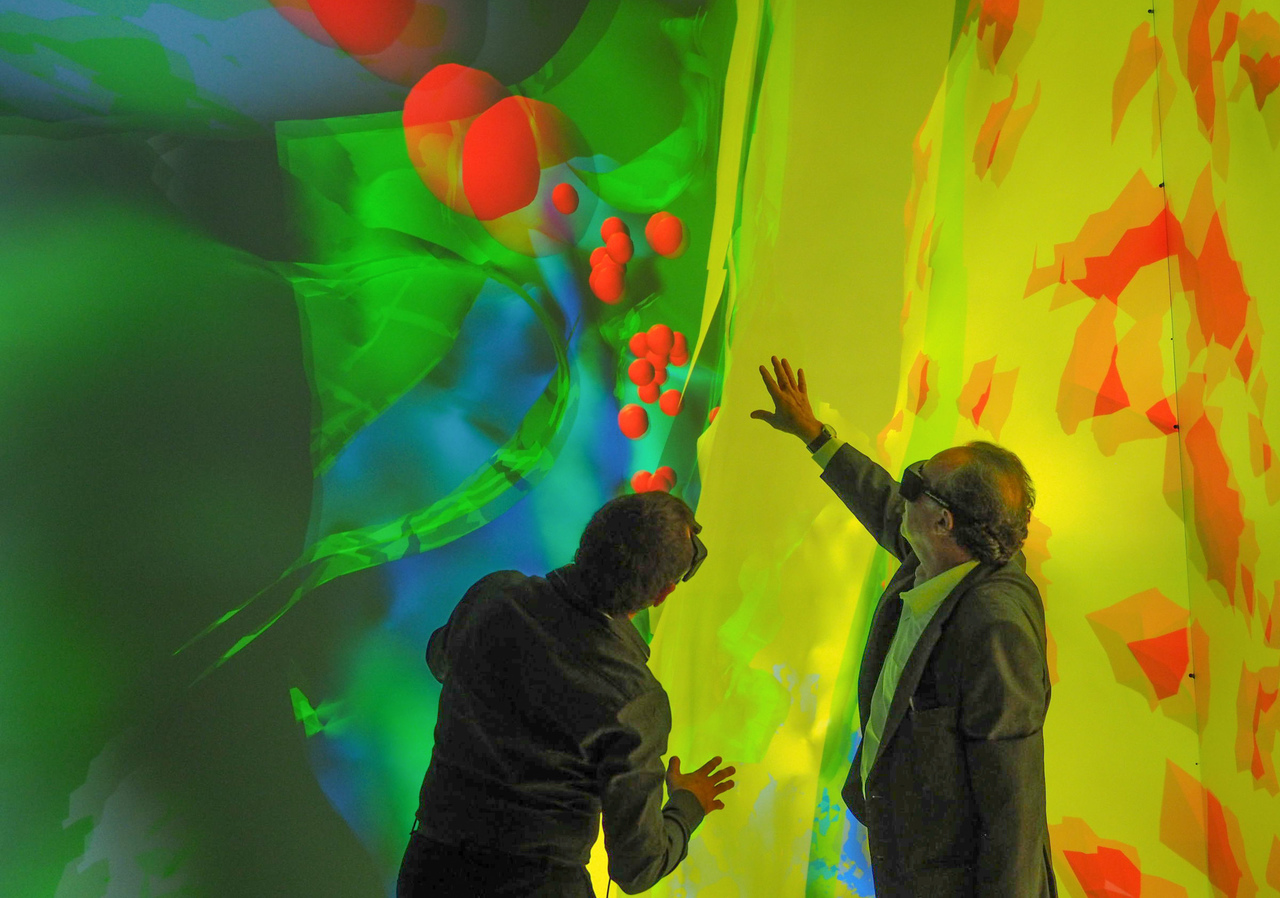
Virtual Reality is an important field for parallel rendering. It requires special attention to support it as a first-class citizen in a generic parallel rendering framework. Equalizer has been used in many virtual reality installations, such as the Cave2 [Febretti et al., 2013], the high-resolution C6 CAVE at the KAUST visualisation laboratory, and head-mounted displays (Figure 1.1). In the following we lay out the features needed to support these installations, motivated by application use cases.
3.4.1 Head Tracking
Head tracking is the minimal feature needed to support immersive installations. Equalizer does support multiple, independent tracked views through observer abstraction. Built-in VRPN support enables the direct, application-transparent configuration of a VRPN tracker device. Alternatively, applications can provide a tracking matrix. Both CAVE-style tracking with fixed projection surfaces, and HMD tracking with moving displays are implemented.
3.4.2 Dynamic Focus Distance
To our knowledge all parallel rendering systems have the focal plane coincide with the physical display surface. For better viewing comfort, we introduce a new dynamic focus mode, where the application defines the distance of the focal plane from the observer, based on the current lookat distance.
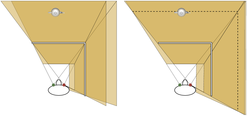
Figure 3.6 illustrates this feature in a top-down view of a Cave. The observed teapot is significantly behind the front projection wall in the virtual world. In a standard implementation (left side), the focal plane coincides with the projection surface. In our implementation, the application configures a focus distance to coincide with the observed teapot (right side). The dotted line shows the focal plane for both projection walls. Initial experiments show that this provides better viewing comfort, in particular for objects placed in front of the physical displays.
3.4.3 Asymmetric Eye Position
Traditional head tracking computes the left and right eye positions by using an interocular distance. However, since human heads are not symmetric, we support an optional configuration of individual, measured 3D eye translations relative to the tracking matrix.
3.4.4 Model Unit
This model unit allows applications to specify a scaling factor between the model and the real world, allowing exploration of macroscopic or microscopic worlds in virtual reality. The unit is per view, allowing different scale factors within the same application. It scales both the specified projection surface, as well as the eye position (and therefore eye separation) to achieve the necessary effect.
3.4.5 Runtime Stereo Switch
Applications can switch each view between mono and stereo rendering at runtime, and run both monoscopic and stereoscopic views concurrently. This switch does potentially involve the start and stop of resources and processes for passive stereo or stereo-dependent task decompositions.
3.5 Tiled Display Walls
Simulations performed on today’s high performance supercomputers produce massive amounts of data, which are often too expensive to move to another system. Tiled display walls have proven to help understand complex data due to their size, resolution and collaborative usage. Often the two systems are not located in the same facility because of power constraints or other factors.
figureO.618
![[Uncaptioned image]](/html/1902.08755/assets/images/tide.png) Tiled Display Wall with Remote Rendering of the Equalizer-based RTNeuron Application
Tiled Display Wall with Remote Rendering of the Equalizer-based RTNeuron Application
Software for driving tiled display walls has converged on the collaborative aspect of these installations. Sage, Sage 2, DisplayCluster and Omegalib implement a multi-window environment around a shared framebuffer concept. DisplayCluster provides a dynamic, desktop-like windowing system with built-in media viewing capability, that supports ultra high-resolution imagery and video content, as well as remote streaming allowing arbitrary applications from remote sources to be shown. Figure 3.5 shows our evolution of DisplayCluster called Tide [Blue Brain Project, 2016] running on a 24 megapixel, tiled display wall.
Streaming to a Tide wall is implemented using the Deflect [Nachbaur et al., 2014] client library. The application provides an image buffer to Deflect, which will be compressed using libjpeg-turbo, and sent asynchronously and in parallel by the stream library. Multiple stream sources from multiple processes can provide content to a single wall window, enabling parallel streaming for parallel rendering applications. Deflect also implements an event model, where the application registers to receive keyboard, mouse and window management events from the wall.
We integrated the stream library into Equalizer to send the framebuffer of each destination channel of a view to DisplayCluster, using a direct FBO download (if possible) or a texture download. We use asynchronous transmission to pipeline compression, streaming, and rendering. Received events from DisplayCluster are converted and forwarded to Equalizer’s event system. This integration allows all Equalizer applications to benefit from streaming without code changes, configured by specifying the DisplayCluster hostname on all views to be streamed.
figureO.618
![[Uncaptioned image]](/html/1902.08755/assets/x15.png) Remote Streaming Scenario
Remote Streaming Scenario
We evaluated the overall system performance using the Blue Brain Project setup shown in Figure 3.5. The supercomputer and data is located in a remote supercomputing centre in Lugano, whereas the tiled display wall is at the project’s main office in Lausanne. Both locations are linked using a high-speed WAN link. The HPC installation has a colocated visualisation cluster for remote rendering scenarios.
![[Uncaptioned image]](/html/1902.08755/assets/x16.png)
Benchmark 3.a shows the performance of streaming RTNeuron rendering from the Lugano cluster to the remote 24 Megapixel wall. We tested three resolutions (, and ), and four different tile sizes (, , and ). Due to a configuration issue, the WAN link delivered only 1 GBit/s throughput during the benchmark. RTNeuron is an Equalizer-based application used in the Blue Brain Project to analyse results from detailed simulations of neuronal simulations.
The results show that interactive frame rates are available even at the full native resolution, that a tile size is the best option, and that 95% compression delivers the best performance in most cases. Based on the experiments we settled on a tile size and 100% compression quality to avoid artefacts as the default settings in Equalizer.
Decoupling the display system and software from the rendering system has many benefits. It increases robustness, provides reliably performance on a shared, collaborative device, facilitates media and device inteagration, and minimises data movement.
3.6 Compositing
In contrast to most other parallel rendering frameworks, Equalizer decouples the compositing algorithm from the task decomposition. This is a key aspect of our architecture, allowing a flexible configuration, often in many unforeseen ways. The compound tree with its task decomposition, input and output frames, is a specialised description to “program” scalable rendering across parallel resources.
Compositing is configured using output frames connected to input frames, compound tasks and eye passes, as well as frame parameters. In its simplest form, a sort-first source compound provides an output frame, which is routed to an input frame using the same name on the destination compound. The source viewport decomposes the task, and the output frame collects this partial result from the source channel to composite it using the correct offset onto the destination channel.
Frame parameters customise pixel handling. They include the transfer buffers (colour, depth), partial channel viewport, pixel zooming (upscale and downscale), and transport method (on-GPU texture or CPU memory). An output frame may be connected to multiple input frames. Frame parameters are used together with compound tasks for parallel compositing, and advanced features such as monitoring and dynamic frame resolution, introduced in Chapter 6.
figureO.618
![[Uncaptioned image]](/html/1902.08755/assets/x17.png) Direct Send Compositing
Direct Send Compositing
Figure 3.6 shows the pixel flow of direct send compositing for a three-way sort-last decomposition, where the destination channel also contributes to the rendering. In the first step, each channel exchanges two colourdepth tiles with its neighbours, and then -composites its own tile. This yields one complete tile on each channel, of which two colour tiles are then assembled on the destination channel, where the third tile is already in place.
The corresponding compound tree is shown schematically in Figure 3.6. Each of the three channels has a child compound to execute the rendering and read back two incomplete tiles for sort-last compositing on the corresponding two sibling compounds. These three leaf compounds represent the first step in Figure 3.6. One level up, each channel receives two tiles and assembles them onto its partially rendered result, creating a complete tile (middle step in Figure 3.6). For the two source-only channels, a final colour-only output image is connected to the destination channel. The arrows illustrate the pixel flow for one of the tiles.
figureO.618
![[Uncaptioned image]](/html/1902.08755/assets/x18.png) Direct Send Compound
Direct Send Compound
For most rendering applications even a relatively complex setup such as this example requires very little programmer involvement. The abstractions provided by the resource description, render context and compounds enable Equalizer to reconfigure the application almost transparently. For polygonal rendering, it suffices that the application honours the range parameter of the render context to decompose its rendering. All other tasks, in particular the parallel compositing and pixel transfers, are fully handled by Equalizer. Applications which require ordered compositing, for example volume rendering, overwrite the assemble callback to reorder the input frames correctly, before passing them on to the compositing code.
The abstraction through frames is flexible, but still allows many architectural optimisations:
- Unordered Compositing:
-
Unless overwritten by the application, Equalizer will composite all input frames by default in the order they become available, not in the order they are configured. In the example in Figure 3.6, the destination channel will assemble its four input frames one by one as the output frame is received. Due to asynchronous execution and resulting pipelining of operations, the availability changes each frame depending on the runtime of other tasks.
- Parallel Compression, Downloads and Network Transfers:
-
Compressing, transmitting and receiving frames between nodes is handled by threads independent from the render thread. GPU transfers are handled by asynchronous PBO transfers. Pipelining all these operations with the actual rendering significantly minimises the compositing overhead.
- On-GPU Transfers:
-
Occasionally the source and destination channel are on the same GPU. Using textures as pixel buffers minimises overhead for the output to input frame transfer.
In Chapter 5 we provide detailed information on our compositing advances.
3.7 Load Balancing
Compounds provide only a static configuration of the parallel rendering setup. Equalizers are algorithms hooking into a compound and modify parameters of their respective subtree at runtime, to dynamically optimise the resource usage. Each equalizer focuses on tuning one aspect of the decomposition, allowing them to be composited in a configuration. Due to their nature, they are transparent to application developers, but might have application-accessible parameters to tune their behaviour. Resource equalisation is the critical component for scalable parallel rendering, and therefore the eponym for the Equalizer project name.
Compounds are a static snapshot of a configuration, and equalizers provide dynamic configuration on top. This separation of responsibilities is an important architectural component of our parallel rendering framework. In Chapter 6 we provide an extensive overview over the available equalizers.
3.8 Runtime Reconfiguration
Supported by the distributed execution layer, introduced in the next section, Equalizer implements dynamic reconfiguration of a running visualisation application. This functionality is used by runtime layout switches and runtime reliability.
Runtime reconfiguration is designed to be a side effect of the internal resource management algorithm, that is, the initialization and exit of a configuration uses the same code path as the runtime addition of a single channel. Rendering resources in Equalizer are reference counted by the compounds using them, and the state change from inactivated to activated triggers a launch or stop of the associated resource. These resource counters are propagated up the resource hierarchy: A channel will (de)activate its window, pipe and node.
Channel and window (de)activation are relatively lightweight and only incur the creation and initialisation of the class instance (and associated OpenGL resources) on the client. A pipe (de)activation incurs additionally a new (or removed) operating system thread, and a node (de)activation is tied to a process. Depending on the application logic, at some level of the resource hierarchy application data has to be distributed to the rendering client. An application may use pre-launched rendering clients which run even when not active, and can use this to cache application state for faster reconfiguration.
Layout switches are caused by the activation of a different layout on a canvas by the application code. A typical layout switch will only (de)active channels, which is a very lightweight operation. Since each combination of a layout and a canvas creates a unique set of destination channels, the destination compounds of these channels may use a different set of source channels for rendering, which may reside on different GPUs or even nodes in the cluster. Some configurations use a different number of rendering GPUs or even nodes, causing the startup or exit of new rendering processes in the cluster.
Runtime reliability detects failed nodes in a visualisation cluster, independent of the cause (hardware or software failure). The server tracks a ‘last seen’ time stamp for each node. When waiting for a task to finish, the server uses this time stamp to detect failures. Potentially failed nodes are pinged with a special command, which is processed even if all application threads are busy. Nodes still answering this command are considered alive for a longer period, after which they are considered failed, likely due to an infinite loop in the application code. Failed nodes are removed from the configuration, and their associated compounds are deactivated. In the case of load balanced source channels, the load equalizer will simply reassign the work to other source channels. For static configurations, the source channel contribution will be missing from the final image. For destination channels, the corresponding output display will disappear from the configuration.
3.9 Distributed Execution Layer
An important part of writing a parallel rendering application is the communication layer between the individual processes. Equalizer relies on the Collage network library for its internal operation. Collage provides networking functionality of different abstraction layers, gradually providing higher level functionality for the programmer. Figure 3.7 shows the main primitives in Collage:
- Connection
-
A stream-oriented point-to-point communication line. Connections transmit raw data reliably between two endpoints for unicast connections, and between a set of endpoints for multicast connections. For unicast, process-local pipes, TCP and InfiniBand RDMA are implemented. For multicast, a reliable, UDP-based protocol is discussed in Section 7.3.
- DataI/OStream
-
Abstracts the marshalling of C++ classes from or to a set of connections by implementing output stream operators. Uses buffering to aggregate data for network transmission. Performs byte swapping during input if the endianness differs between the remote and local node.
- Node and LocalNode
-
The abstraction of a process in the cluster. Nodes communicate with each other using connections. A LocalNode listens on various connections and processes requests for a given process. Received data is wrapped in ICommands and dispatched to command handler methods. A Node is a proxy for a remote LocalNode.
- Object
-
Provides object-oriented and versioned data distribution of C++ objects between nodes. Objects are registered or mapped on a LocalNode.
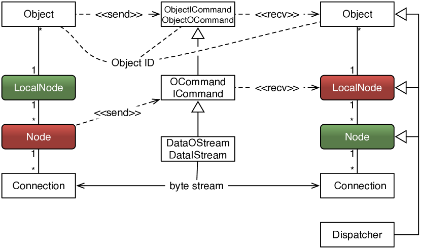
Collage implements a few generic distributed objects, which are used by Equalizer and other applications. A barrier is a distributed primitive used for software swap synchronisation. Its implementation follows a simple master-slave approach, which has shown to by sufficient for this use case. Queues are distributed, single producer, multiple consumer FIFO queues are used for tile and chunk compounds (Section 4.2.4). To hide network latencies, consumers prefetch items.
An object map facilitates distribution and synchronisation of a collection of distributed objects. Master versions can be registered on a central node, e.g., the application node in Equalizer. Consumers, e.g., Equalizer render clients, can selectively map the objects they are interested in. Committing the object map will commit all registered objects and sync their new version to the slaves. Syncing the map on the slaves will synchronise all mapped instances to the new version recorded in the object map. This effective design allows data distribution with minimal application logic.
Chapter 7 contains more information on our network library.
Chapter 4 Scalable Rendering
4.1 Overview
Scalable rendering is a subset of parallel rendering which aims to improve the framerate of a rendering work load by decomposing it over multiple rendering resources. Parallel rendering includes other use cases, for example to use multiple GPUs to drive individual displays of a tiled display wall. This chapter addresses the research question on how we can improve the rendering performance of visualisation applications to enable users to explore more data.
Scalable rendering research has put a lot of focus on two of the three architectures classified by [Molnar et al., 1992]: sort-first and sort-last rendering. Sort-middle rendering is still largely confined to hardware implementations due to its high communication cost of sorting and distributing fragments to processing units.
In this chapter, we present new parallelisation variants of sort-first rendering, and other decompositions which break out of this standard classification. For each mode, we introduce its algorithm and implementation, potential impact on the application code, as well as its strengths and weaknesses. Due to the flexible architecture of our parallel rendering system, these modes are largely usable with any Equalizer application and can be combined with all other modes.
Most of these rendering modes are similar to sort-first rendering, in that they decompose the final view spatially or temporally, while computing complete pixels on each source channel. Stereo compounds decompose per eye pass, DPlex compounds temporally, pixel and subpixel compounds use equal spatial decompositions. Finally, tile and chunk compounds implement implicit load balancing for sort-first and sort-last rendering using queueing of work items.
This wide set of decomposition modes for scalable rendering, embedded in our generalised compound structure, enables applications and researchers to decompose the rendering task in, as far as we know, any way possible for a rendering pipeline. To our knowledge no other implementation provides this breath and flexibility, and some algorithms appear for the first time in Equalizer.
4.2 Sort-First
Sort-first rendering decomposes the rendering task in screen space. It has many variants: tiled display walls and similar installations perform sort-first parallel rendering naturally by using multiple GPUs to drive the output displays, and classic sort-first scalable rendering assigns one screen-space region to each rendering resource, often combined with load balancing. Equalizer supports these classic sort-first modes. In the following subsections we present other variants of sort-first rendering, each tailored to a certain use case.
4.2.1 Stereo
figureO.618
![[Uncaptioned image]](/html/1902.08755/assets/x20.png) Anaglyphic Stereo Compound
Anaglyphic Stereo Compound
Stereo, or eye decomposition, is a specialised version of sort-first rendering. Two GPUs get assigned each one of the eye passes during stereo rendering. For passive stereo, there is no compositing step needed, whereas for active and anaglyphic stereo the frame buffer for one eye pass has to be copied to the destination channel. Due to the strong similarity between both eye passes, this mode provides close to perfect load balance. Figure 4.2.1 shows an anaglyphic stereo compound.
While many visualisation applications provide passive or active stereo rendering and sometimes decomposition using two GPUs, our implementation within our flexible compound structure allows to fully exploit stereo decomposition. Stereoscopic and monoscopic rendering is no special case in the architecture, but rather a configuration of the rendering resources. Among other things, this allows extending a two-way stereo decomposition with further resources and any other scalable rendering mode. One can also easily set up an application with mixed rendering, e.g., to render a monoscopic view on a control workstation while rendering stereoscopic on a larger immersive installation.
Stereo compounds are configured by restricting each source to a single eye pass. Typically, one of the channels also configures the cyclop eye pass, which gets activated when the view is switched to monoscopic rendering.
4.2.2 Pixel
figureO.618
![[Uncaptioned image]](/html/1902.08755/assets/x21.png) Pixel Compound
Pixel Compound
Pixel compounds (Figure 4.2.2) decompose the destination channel by interleaving pixels in image space. They are a variant of sort-first rendering well suited for fill-limited applications which are not geometry bound, for example direct volume rendering. Source channels cannot reduce geometry load through view frustum culling, since each source channel has almost the same frustum as the destination channel. However, the fragment load on all source channels is reduced linearly and well load balanced due to the interleaved distribution of pixels. This functionality is transparent to Equalizer applications, and the default compositing uses the stencil buffer to blit pixels onto the destination channel.
Pixel compounds are configured by restricting each source compound with a pixel kernel. The kernel describes the size of the decomposition in 2D space, and the 2D pixel offset within this region. This follows our design philosophy of enabling features by generalising the underlying algorithm rather then hardcoding them.
4.2.3 Subpixel
figureO.618
![[Uncaptioned image]](/html/1902.08755/assets/x22.png) Subpixel Compound
Subpixel Compound
Subpixel compounds (Figure 4.2.3) are similar to pixel compounds, but they decompose the work for a single pixel, for example during Monte-Carlo ray tracing, FSAA or depth of field rendering. The default compositing algorithm uses accumulation and averaging of all computed fragments for a pixel. Like Pixel compounds, this mode is naturally load balanced on the fragment processing stage but cannot scale geometry processing. This feature is not fully transparent to the application, since it decomposes rendering algorithms which render multiple samples per pixel. Applications needs to adapt their rendering code, for example to jitter or tilt the frustum based on the subpixel executed in the current subpixel rendering pass.
Subpixel compounds increase the amount of pixels to be composited linearly with the number of source channels. They can use the same parallel compositing algorithms as sort-last rendering. Since the compositing logic is decoupled from the task decomposition, it reuses the same code as sort-last parallel compositing except for the combination step on each GPU.
Subpixel compounds are configured on each source compound with a subpixel kernel. This kernel describes the number of contributing sources, and the offset for each source in this range.
4.2.4 Tiles
figureO.618
![[Uncaptioned image]](/html/1902.08755/assets/x23.png) Tile Compound
Tile Compound
Tile (Figure 4.2.4) decompositions are a variant of sort-first rendering. They decompose the scene into a set of fixed-size image tiles. These tasks, or work packages, are queued and processed by all source channels by polling a server-central queue. Prefetching ensures that the task communication overlaps with rendering.
As shown in [Steiner et al., 2016], work packages can provide better performance due to being implicitly load balanced, as long as there is an insignificant overhead for the render task setup. This mode is transparent to Equalizer applications. We have used a tile compound to scale an interactive ray tracing application to hundreds of rendering nodes using RTT Deltagen.
Tile compounds are configured using output and input queues. The destination channel has an output queue, which configures the tile size and represents the server-side end of the task queue. Each source compound has an input queue of the same name, which represents the client-side queue end polling tasks from the server. Output frames from tile sources are automatically configured with the current tile offset and size for correct assembly on the destination channel.
4.3 Sort-Last
Sort-last rendering decomposes the rendering task in object space, that is, each rendering resource produces an incomplete full-resolution image. To our knowledge, sort-last rendering always requires a compositing step, which is the challenging part for this decomposition mode. It is often addressed using parallel compositing, which we discuss in Section 5.2.
Equalizer does support classical sort-last rendering with or without load balancing, where each resource renders one part of the applications database. Furthermore, we also implement chunk compounds, which are similar to tile compounds (Section 4.2.4), with which they share a lot of the infrastructure. Chunk compounds also produce work packages, although using a fixed-size subrange of data for each package instead of the tile coordinates used for tile compounds.
4.4 Time-Multiplex
Time-multiplexing distributes full frames over the available resources, such that each resource only renders a subset of the visible frames (Figure 4.4). This mode is also called alternate frame rate or DPlex, was first implemented in [Bhaniramka et al., 2005] for shared memory machines. The algorithm is however much better suited for distributed memory systems, since the separate memory space makes concurrent rendering of different frames much easier to implement. While it increases the framerate almost linearly, it cannot improve the latency between user input and the corresponding output. At best, it can achieve the same latency compared to the single-GPU case, when perfect linear scalability is achieved. Consequently, this decomposition mode is mostly useful for non-interactive film generation.
figureO.618
![[Uncaptioned image]](/html/1902.08755/assets/x24.png) Time-Multiplex Compound
Time-Multiplex Compound
DPlex is very well load balanced, since most applications observe a strong frame-to-frame coherence with respect to the rendering load. This decomposition mode has the peculiarity that small imbalances tend to accumulate such that the concurrent frames all finish simultaneously. To provide a smooth framerate, if so desired, a framerate equalizer can be installed on the destination compound. Section 6.5 covers this functionality. It is transparent to Equalizer applications, but does require the configuration latency to be greater or equal to the number of source channels.
DPlex rendering is not hard-coded into our framework, but configured by restricting the rendering task temporally on each source compound. This is achieved by setting a period and phase parameters, which configure the number of frames skipped and starting offset on the given source compound. A simple DPlex compound would have a destination compound with source compounds, where each source has a period of and one phase from . While this generalization may seem artificial, it opens up different use cases, for example giving a fast GPU a smaller period, thus giving it more work.
4.5 Stereo-Selective Compounds
Stereo-selective compounds have different configurations, depending on the current rendering mode. Each compound sub-tree can restrict the eye passes it renders from the default left, right, cyclop passes. Depending on the active stereo mode (stereo or mono), restricted compound trees may be skipped or activated. This is used on one hand to configure stereo compounds, but may also be used to configure different decompositions depending on the stereo mode. Figure 4.1 shows a simple example: A dual-GPU setup is used with eye-parallel rendering during stereo rendering, and a standard sort-first parallel rendering during monoscopic rendering. Note that the rendering mode is runtime-configurable, that is, the application can switch the view from monoscopic to stereoscopic rendering at any time, activating and deactivating the configured compounds and attached resources. It is also possible to configure a different set of resources (nodes and GPUs) per stereo mode, triggering the launch and exit of render client processes during the stereo switch.
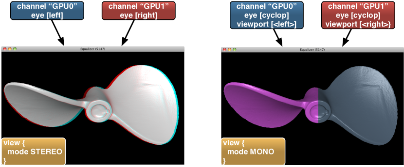
4.6 Mixed Mode Compounds
A major contribution of our parallel rendering system is the flexible system architecture. While many applications and frameworks implement a subset of the features mentioned above, most of them hardcode the algorithms, predetermining the number of possible configurations. In Equalizer, both the decomposition and the recomposition of the rendering task are derived through a number of orthogonal parameters, which are easily combined to configure common scalable rendering modes. For advanced usage, they can also be configured for many other use cases. During deployment of Equalizer, we have seen many interesting and unforeseen configurations:
-
•
Reusing the period parameter used to configure number of frames in a DPlex compound, an underpowered control workstation for a large tiled display wall was configured to render only every other frame using a period of two. Due to the standard latency of one frame, this meant that the display wall rendering became the bottleneck. It could now render at a substantially higher framerate than before, when the control host was the bottleneck.
-
•
Rerouting one of the eye passes of a head-mounted display to a large display using an output and input frame, external users could observe the interaction and view of the person using the HMD. The same can be achieved by mirroring the video signal by other means, but this was not available on the given setup.
-
•
Using combined stereo and sort-first decomposition on the central tiles of a tiled display wall. Often times the central tiles of a tiled display wall receive a higher rendering load then the outer tiles. In this particular configuration, each tile was driven by a dual-GPU node using active stereo compounds, and the middle segments where given an additional machine setting up a two-way sort-first decomposition under each node of the two-way stereo compound.
-
•
Combined sort-last and sort-first decomposition: Sort-first rendering is typically limited in the scalability of the decomposition step, where geometry overlap between resources often yields diminishing returns after about ten GPUs. Sort-last rendering on the other hand is often limited by the overhead of the compositing step. Combining both modes enables to balance these constraints for better scalability.
4.7 Benchmarks
Benchmarks for static compound configurations are relatively rare, since most practical settings use some type of load balancing. They are however interesting in that they show how well different rendering algorithms are naturally load-balanced. In [Eilemann et al., 2018], we collected some data for polygonal and volume rendering. Benchmark 4.b provides a strong scalability benchmark for both types of rendering and a set of compounds. The linear scaling graph provides a theoretical limit for perfect scalability compared to the single-threaded, single-GPU rendering performance.
![[Uncaptioned image]](/html/1902.08755/assets/x26.png)
For static task decomposition, polygonal rendering performs better with sort-last compared to sort-first. Sort-last performs a static decomposition in data space, which reduces the geometry processing load per GPU, which is the dominant factor in our polygonal rendering code. Since this decomposition can be computed easily, even a static decomposition is relatively balanced. A sort-first decomposition can reduce the geometry processing through view frustum culling, but the remaining visible set will be relatively unbalanced on each GPU, depending on the current camera position.
For volume rendering, this balance is reversed and sort-first performs better. Typically, a volume renderer is bound by fragment processing. Consequently, sort-first rendering scales better than sort-last, since the screen-space is equally divided. For both rendering algorithms, one can observe static imbalances in the zig-zag graphs, where odd number of resources coincidentally split the rendering load less balanced than even numbers.
Tile compounds provide close to linear scalability, and in some cases super-linear scaling. Compared to the other compounds, tile compounds are naturally load balanced, providing this excellent scalability relative to static sort-first and sort-last. Super-linear scaling is due to their small work package size, which makes rendering more cache-friendly. Polygonal rendering has a higher static overhead per tile due to the CPU-side view frustum culling, and therefore scales less well compared to volume rendering.
Pixel compounds provide predictable scalability, but fail to approach ideal linear scaling due to their increased compositing cost and constant geometry load.
Chapter 5 Compositing
5.1 Overview
Compositing collects and combines partial results from multiple resources during scalable rendering onto one or more destination channels. While significant characteristics of the decomposition step, discussed in the previous chapter, are dependent on the application rendering code, compositing is largely a generic problem and can be implemented and optimised in a parallel rendering framework. Consequently, this area of parallel rendering research has received significant attention. By integrating many state-of-the art optimisations into our parallel rendering framework, we provide a generic solution that scales well on modern visualisation cluster architectures.
We present new insight into the behaviour of known sort-last parallel compositing algorithms on mid-size visualisation clusters (compared to high-end HPC systems), the importance of streaming sort-last compositing and spatial sort-last polygonal rendering, the impact of state of the art optimisations such as region of interest and asynchronous compositing, as well as image compression algorithms for high-speed interconnects. This chapter addresses the research question which new algorithms will decrease the time needed to composite rendering results, in particular for sort-last rendering.
5.2 Parallel Compositing
Parallel compositing leverages multiple compute resources, memory bandwidth and network bandwidth within a visualisation cluster to accelerate the compositing step in parallel rendering. During sort-last and subpixel decompositions, each rendering resource produces an output which needs to be combined with the result of other resources on a per-pixel level. This compositing step reduces the amount of information, either through depth-sorting or blending multiple input fragments into a single pixel. This loss of information in the compositing step can be exploited by distributing the work over multiple resources, and then collecting the reduced image tiles, commonly called parallel compositing.
5.2.1 Spatial and Depth-Sorted Sort-Last Compositing
For sort-last rendering, two approaches to combine the partial results exist: -sorting using the depth buffer, and spatial rendering decomposition with ordered compositing.
The first algorithm uses both the colour and depth buffer, and assigns the final pixel to the colour of the source with the front-most depth buffer values. It requires no spatial ordering of the data during rendering. It does not correctly composite pixels with transparent geometry, since there is no guarantee of the blending order. Owing to the use of the depth buffer, it is also more expensive, since both color and depth data needs to be processed. Furthermore, depth buffer readback tends to be slower, and compression algorithms for depth buffer data do not to perform as well as colour buffer compression. Depth-sorted compositing is often used for polygonal data, as shown in Figure 5.1, since these applications often do not sort their geometry into convex spatial regions.
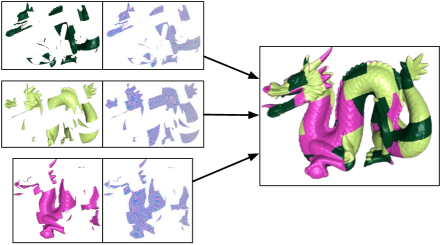
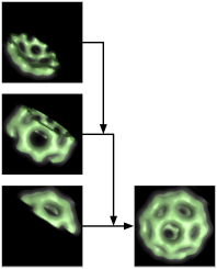
Spatial compositing is often used for direct volume rendering and requires the application to render convex regions of data on each source, and then depth-sort the partial images produced by each source. The partial images are composited in order, typically with alpha-blending. Since the sorting happens at the image level, rather then the fragment level as in the first algorithm, it can operate using only the colour buffer, as shown in Figure 5.1. This algorithm can produce correct transparency, since the convex regions allow ordered blending.
Spatial compositing provides better performance, and better scalability when used with other optimisations, such as region of interest and load balancing due to compact regions produced by the spatial sorting. Typically used for volume rendering, we have applied spatial sort-last rendering and compositing to polygonal data, by sorting the data spatially and using clipping planes to generate perfectly convex rendering subsets.
benchmarkO.618
![[Uncaptioned image]](/html/1902.08755/assets/x29.png) Spatial versus Depth-Sorted Sort-Last Rendering
Spatial versus Depth-Sorted Sort-Last Rendering
Benchmark 5.2.1 shows the difference between spatial and depth-sorted sort-last rendering in RTNeuron (Section 8.3). Due to complexities in the application data model and the disadvantageous geometrical structure of neurons, the spatial rendering in RTNeuron scales less than the round-robin allocation used for the depth-sorted mode. Still, owing to the significantly reduced compositing load of this mode, both due to a smaller region of interest and no depth buffer transfers, spatial sort-last rendering has a significantly better framerate. The exact experiment setup can be found in [Eilemann et al., 2012].
5.2.2 Direct Send and Binary Swap
Contrary to most other implementations, parallel compositing algorithms in Equalizer are not hardcoded, but rather configured explicitly. The transport of pixel data for compositing is expressed through connected output and input frames. Output and input frames are connected by name; they do not need to follow the compound hierarchy, and a single output frame may be consumed by multiple input frames. Output frame parameters configure a subset of the rendering (viewport and framebuffer attachments), and are read back after rendering and assembly. Furthermore, every step of the compositing pipeline is implemented in Equalizer and transparent for the application developer. Some steps may be replaced with application code, for example ordering frames during compositing.
Two commonly used parallel compositing algorithms are direct send and binary swap. Both distribute the compositing task equally over all available resources, then collect the composited tiles on the destination channel.
Direct send, shown in Figure 3.6, uses one assemble operation on each resource to fully composite a single tile. Binary swap, shown in Figure 5.2, exchanges pixels between pairs of nodes using a binary compositing tree which gradually assembles a tile on each resource. Both use a sort-first-like assembly operation to collect the fully assembled tiles on the destination channel. 2-3 swap [Yu et al., 2008] is an extension to binary swap, which overcomes the power-of-two source channel requirement by exchanging compositions between groups of two or three nodes in the compositing tree.
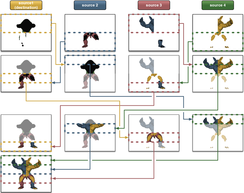
In [Eilemann and Pajarola, 2007] we have shown that on commodity clusters, direct send compositing provides better performance over binary swap commonly used on HPC systems. While it uses more messages in total, direct send has fewer synchronisation points than binary swap. Moreover, as a result of the early assembly optimisation (Section 5.6), direct send can handle imbalances between nodes better, since a late channel has a smaller penalty on the overall execution time.
5.2.3 Streaming Sort-Last Compositing
As a result of the asynchronous architecture of our framework, streaming sort-last compositing is a viable alternative to more involved parallel compositing algorithms in smaller sort-last configurations.
Figure 5.3 shows a streaming sort-last compound. The output of one source channel is copied to the next channel in the chain, which then composites it on top of its own rendering, streaming the combined frame on to the next source. At the end of the chain, the destination channel completes the input frame by compositing it with his rendering.
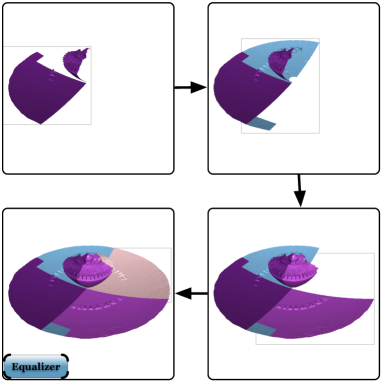
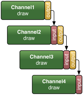
Equalizer only synchronises the input to the output frames, therefore this configuration creates a pipelined configuration, where the compositing operations form the “critical path”. Each channel has its draw pass delayed by the time taken by all preceding compositing operations, as shown schematically in Figure 5.3. This pipelining emerges naturally due to the synchronisation points introduced by the compositing configuration.
The total system latency for sort-last stream compounds is . Note that the readback and assemble times are usually an order of magnitude smaller than the render time, which makes this compound attractive for small-to-medium sized decompositions, since it has minimal compositing overhead and less synchronization compared to parallel compositing algorithms.
5.3 Region of Interest
During scalable rendering pixel data has to be copied from the source channel framebuffer to either the destination channel framebuffer, or to an intermediate channel during parallel compositing. The associated distributed image compositing cost is directly dependent on how much data has to be sent over the network, which in turn is related to how much screen space is actively covered. For sort-last rendering every node potentially renders into the entire frame buffer, resulting in a linear increase in the amount of pixels composited for an increasing number of nodes. Depending on the data set and viewpoint, only a subset of the framebuffer shows pixels generated from the data. With an increasing number of nodes, the set of affected pixels typically decreases, leaving blank areas that can be omitted for transmission and compositing.
Equalizer provides an API for the programmer to provide the region of interest (ROI). The ROI is the screen-space 2D bounding box fully enclosing the data rendered by a single resource, which can be easily computed by calculating the screen-space projection of the model’s bounding volume. We have extended the core parallel rendering framework to use this application-provided ROI to optimise the load_equalizer and tree_equalizer, as well as image compositing.
Figure 5.3 outlines the region of interest of each source. The compositing code uses the ROI to minimise image readback size, and consequently network transmission. The ROI is an output frame parameter, and is transmitted to all input frames together with the pixel data. On the input frame, the compositing code respects this parameter to place the pixel data in the right position. Further, the ROI of the rendering pass is automatically merged with the ROI of the composited frames for readback. The usage of ROI for load balancing is described in Section 6.2.
Applying ROI for sort-first rendering provides a small improvement for the rendering performance, as shown in Benchmark 5.c(a) from [Eilemann et al., 2012]. As the number of resources increases, the ROI becomes more important since the relative amount of time spent in compositing increases with the rendering load decreasing. With ROI enabled we observed performance improvements between 5-20%, reaching 60 Hz when using 33 GPUs. Without ROI, the framerate peaked at less than 50 Hz when using 27 GPUs.
![[Uncaptioned image]](/html/1902.08755/assets/x33.png)
![[Uncaptioned image]](/html/1902.08755/assets/x34.png)
(a) (b)
ROI is crucial for sort-last rendering performance. In our experiments in [Eilemann et al., 2012], we used a polygonal renderer creating relatively compact regions during sort-last decomposition, while still using depth-sorted compositing (cf. Figure 5.3). This is a relatively common use case for sort-last rendering. In this mode, we can observe significant speedups with ROI (up to 4x), as shown in Benchmark 5.c(b). In [Makhinya et al., 2010] this application-provided ROI was extended by an algorithm which automatically computes the ROI by analysing the framebuffer. This algorithm has the advantage of simplifying the application developers’ life, and can also conveniently detect holes in the rendered framebuffer.
5.4 Asynchronous Compositing
Asynchronous compositing pipelines pixel transfers with rendering operations by moving them to a separate thread. Compositing in a distributed parallel rendering system is decomposed into readback of the produced pixel data (1), optional compression of this pixel data (2), transmission to the destination node consisting of send (3) and receive (4), optional decompression (5) and composition consisting of upload (6) and assembly (7) in the destination framebuffer.
benchmarkO.618
![[Uncaptioned image]](/html/1902.08755/assets/x35.png) Synchronous Readback and Upload
Synchronous Readback and Upload
In a naive implementation operations 1 to 3 are executed serially on one core, 4 to 7 on another. In our parallel rendering system, operations 2 to 5 are executed asynchronously to the rendering operations 1, 6 and 7. Furthermore, we use a latency of one frame which means that two rendering frames are always in execution, allowing the pipelining of these operations, as shown in Figure 5.4. We have implemented asynchronous readback using OpenGL pixel buffer objects, further increasing the parallelism by pipelining the rendering and pixel transfers, as shown in Figure 5.4.
In the asynchronous case, the rendering thread performs only application-specific rendering operations, since the overhead of starting an asynchronous readback becomes negligible. Equalizer uses a plugin system to implement GPU-CPU transfer modules that are runtime loadable. We extended this plugin API to allow the creation of asynchronous transfer plugins, and implemented such a plugin using OpenGL pixel buffer objects (PBO). At runtime, one rendering thread and one download thread are used for each GPU, as well as one transmit thread per process. The download threads are created lazy when needed.
benchmarkO.618
![[Uncaptioned image]](/html/1902.08755/assets/x36.png) Asynchronous Compositing Sort-First Rendering
Asynchronous Compositing Sort-First Rendering
Asynchronous compositing is, together with region of interest, one of the most influential optimisations for scaling rendering to large cluster sizes. For sort-first rendering, shown in Benchmark 5.4 from [Eilemann et al., 2012], pipelining the readback with the rendering yields a performance gain of about 10%. At higher frame rates, when the rendering time of a single resource decreases, asynchronous readback has an even higher impact of over 25%.
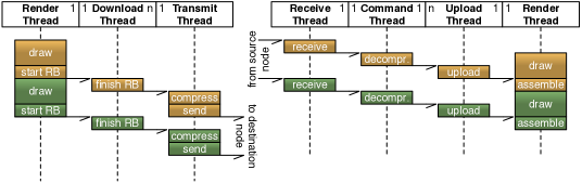
5.5 Compression for Image Compositing
The image compositing stages in distributed rendering are fundamentally limited by the GPU-to-node and node-to-node image data throughput. Efficient image coding, compression and transmission must be considered to minimise that bottleneck.
Basic run-length encoding (RLE) has been used as a fast algorithm to improve network throughput for interactive image transmission. However, it only gives sufficient results in specific rendering contexts and fails to provide a general improvement as shown in [Makhinya et al., 2010]. RLE only works in compacting large empty or uniform colour areas, but is often useless for non-trivial full frame colour results. We developed two enhancements to improve RLE: per-component RLE compression and reordering of colour bits. These preconditioning steps exploit typical characteristics of image data for run-length encoding.
Equalizer also integrates more complex compression algorithms such as lib-jpeg-turbo, which are of little practical use on modern cluster interconnects. Their compression overhead is often too high to be amortised by the decreased network transmission time on 10 GBit/s or faster interconnects. For remote image streaming, as discussed in Section 3.5, they remain a viable compression algorithm.
Based on our work, [Makhinya et al., 2010] implemented GPU-based YUV subsampling before the image download, which has negligible overhead, reasonable compression artefacts, and a good compression ratio.
5.5.1 Enhanced RLE Compression
Run-length encoding (RLE) is a simple compression scheme and is on modern architectures purely constrained by the available memory bandwidth. For image compression in visualisation applications, we can exploit some characteristics of the data to improve the compression ratio over the standard RLE compression.
Our basic RLE implementation is a fast 64-bit version comparing two pixels at the same time (8 bit per channel RGBA format). This choice is motivated by the fact that modern processors have 64 bit registers, thus using 64 bit tokens optimises throughput. While this method is very fast, it shows poor compression results in most practical settings since it can only compress adjacent pixels of the same colour. We have observed a compression rate of up to 10% in practical scenarios.
figureO.618
![[Uncaptioned image]](/html/1902.08755/assets/x38.png) 64 bit and Per-Component RLE Compression
64 bit and Per-Component RLE Compression
The first improvement is to treat each colour component separately by producing four independent RLE-compressed output streams as illustrated in Figure 5.5.1. This per-component RLE improves the compression rate from 10% to about 25%, as individual colour components change less often than full pixels.
The second improvement is bit-swizzling of colour values before per-component compression. This swizzling step is a data pre-conditioner, which reorders and interleaves the per-component bits as shown in Figure 5.5 by grouping them by significance. Now the per-component RLE compression separately compresses the higher, medium and lower order bits in separate streams, thus achieving stronger compression for smoothly changing colour values, since high-order bits change less often.
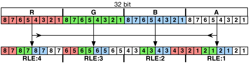
Swizzling improves the compression rate to up to 40% for the same scenario as above. The preconditioning step only requires bit shift and mask operations, is entirely executed in registers and has no measurable impact on performance, since the whole algorithm is memory bound on modern CPUs.
All RLE compressors perform a data decomposition on the input image, and parallelise the compression of the resulting sub-images across multiple threads. This parallel execution improves the performance by saturating multiple memory channels compared to a single-threaded implementation.
benchmarkO.618
![[Uncaptioned image]](/html/1902.08755/assets/x40.png) Image Compression in Sort-First Polygonal Rendering
Image Compression in Sort-First Polygonal Rendering
Benchmark 5.5 summarises the compression results from [Makhinya et al., 2010]. We have chosen sort-first rendering, since this highlights the results for the RLE compressor which is optimised for colour image data. This benchmark did run on a visualisation cluster with Gigabit Ethernet at a resolution of pixels. It rendered the David statuette at 1mm resolution, resulting in a rendering time of about 28 ms on a single GPU. The theoretical maximum line shows the upper limit for sort-first compositing with uncompressed image data and no rendering time. It decreases as the destination channel contributes to the sort-first rendering and does not require a pixel transfer. With an increasing number of remote source channels its size decreases, requiring more pixels to be transferred.
The graph shows how various incremental improvements add up to significant performance gains. Even in a relatively difficult scenario with a fast rendering time, and, by modern standards, slow network interconnect, we were able to more than double the performance to above 60 Hz.
The basic 8-byte RLE Compressor performs just minimally better than no compression. Both stay relatively close the theoretical maximum, but can’t quite reach it due to load imbalances and non-zero rendering time. The swizzling pre-conditioner can significantly reduce the compositing time, and even improve the overall framerate.
The YUV is compressor is an on-GPU compression plugin which performs a color space conversion and lossy chroma subsampling. It can be combined with the CPU-based RLE compressor, which then interleaves and compresses the Y, U and V channels, resulting in major performance improvements. Both compression steps have virtually no computational overhead and are memory bandwidth bound. Since the YUV compressor runs on the GPU, it reduces the costly GPU to CPU transfer time over the PCI Express link.
5.5.2 GPU Transfer and CPU Compression Plugins
Equalizer uses runtime-loadable plugins to transfer pixel data from and to the GPU, as well as plugins to compress and decompress pixel data for network compression. This separation allows different code paths for multi-GPU machines where no CPU-based compression is used, and for distributed execution where data is compressed before network transfer.
The GPU transfer might also apply compression. This is typically done on the GPU to reduce the amount of memory transferred over the GPU-CPU interconnect. One example is YUV subsampling, where a shader implements the RGB to YUV colour space conversion and subsequent chroma subsampling. Furthermore, a GPU transfer plugin may implement asynchronous downloads, where the download is started from the render thread an finished in a separate download thread as shown in Figure 5.4. CPU compression plugins are always executed from asynchronous threads concurrently to the rendering threads.
The implementation of these steps in plugins provides a clean separation and interface for users and researchers interested in experimenting with image compression for interactive parallel rendering.
5.6 Out-of-Order Assembly
Early assembly provides better pipelining when the frame assembly order is not important, for example for sort-first rendering and sort-last rendering with -compositing. Our default compositing code uses a signal on all input frames, which is triggered for each input frame arrival. The compositing code then picks and composites this image, assembling images early and out of order as they become available. This decreases the time to solution, since the assemble operation finishes once the last frame arrives, plus the time to assemble this last frame. In-order assembly would have a statistical probability of frames to assemble after the last frame arrives (unless other constraints make the arrival not fully random or network-constrained).
Chapter 6 Load Balancing
6.1 Overview
Load balancing performs resource assignment per source channel based on workload, with the goal of equalising resource utilisation. Static load balancing, shown in Figure 6.1 top, performs this assignment once during initialisation. Dynamic load balancing can either be reactive or predictive (middle and bottom of Figure 6.1). Reactive load balancing utilises statistics from previous frames to estimate future load distribution. Predictive load balancing uses an application-provided load estimate (also called cost function) to predict the load distribution for the current frame. Both approaches reassign resources dynamically, typically for each rendered frame. Implicitly load balanced algorithms achieve a good load balance by other means, for example by work stealing between resources.
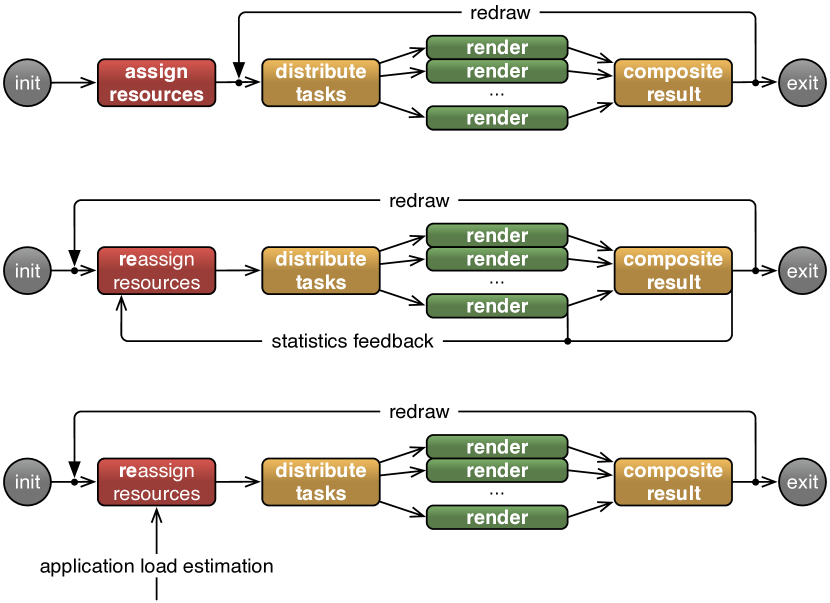
In our framework load balancing is implemented by Equalizers, which are an addition to compound trees. They modify parameters of their respective compound subtree at runtime to dynamically optimise the resource usage, by tuning one aspect of the decomposition or recomposition. Due to their nature, they are transparent to application developers, but might have application-accessible parameters to tune their behaviour. Resource equalisation is the critical component for scalable rendering, and therefore the eponym for the Equalizer project name.
In this section we present various equalizer implementations: two variants for reactive load balancing for sort-first and sort-last rendering, implicitly load balanced work packages for sort-last and sort-first rendering, cross-segment load balancing for multi-display installations, constant frame rate rendering using dynamic frame resolution, and monitoring of large-scale visualisation systems. These equalizers address the research question on how we can improve load-balancing for sort-first rendering, in particular for large display systems.
6.2 Sort-First and Sort-Last Load Balancing
figureO.382
![[Uncaptioned image]](/html/1902.08755/assets/images/loadeq.png) Load Balancing
Load Balancing
Sort-first (Figure 6.2) and sort-last load balancing are the most obvious optimisations for these parallel rendering modes. Our load equalizers are fully transparent for application developers; they use a reactive approach based on past rendering times. This requires a good frame-to-frame coherence for optimal results, which is the case with most rendering applications. Equalizer implements two different algorithms: A load_equalizer and a tree_equalizer, which have shown advantageous for different types of rendering load.
Both equalizers extract their load metrics from statistics collected by the rendering clients, which are sent asynchronously from the clients to the server, where the equalizers subscribe to them for operation. At the beginning of each frame, the server triggers all equalizers on all compound trees, which enables them to set new decomposition parameters before the rendering tasks are computed.
The load_equalizer builds a model of the rendering load in screen space or data space. It stores a 2D (for sort-first) or 1D (for sort-last) grid of the load, mapping the load of each channel. The load is stored in normalised 2D/1D coordinates using as its measure. The contributing source channels are organised in a binary kD-tree. The algorithm then balances the two branches of each level by equalising the integral over the cost area map on each side. This algorithm is similar to [Abraham et al., 2004], which uses a dual-level tree. Our binary split tree provides more compact tiles for larger cluster configurations, since the split direction alternates on each level.
figureO.618
![[Uncaptioned image]](/html/1902.08755/assets/x42.png) Load Cost Area Map with (top) and without (bottom) using Region of Interest Information
Load Cost Area Map with (top) and without (bottom) using Region of Interest Information
The load balancer has to operate on the assumption that the load is uniform within one load grid tile. Naturally this leads to estimation errors, since in reality the load is not uniformly distributed, it tends to increase towards the centre of the screen in Figure 6.2. We reuse the Region of Interest (ROI) from compositing of each source channel to automatically refine the load grid as shown in Figure 6.2, top left. In cases where the rendered data projects only to a limited screen area, this ROI refinement provides the load balancer with a more accurate load estimation, leading to a better load prediction during the balancing step.
The tree_equalizer uses the same binary kD-tree structure as the load_equalizer for recursive load balancing. It computes the accumulated render time of all children for each node of the tree and uses the result to allocate an equal render time to each subtree. It makes no assumption of the load distribution in 2D or 1D space, it only tries to correct the imbalance in render time.
Both equalizers implement tunable parameters allowing application developers to optimise the load balancing based on the characteristics of their rendering algorithm. These parameters are accessible through an API from the application main thread:
- Split Mode
-
configures the tile layout: horizontal stripes, vertical stripes, or 2D, a binary tree split alternating the split axis on each level, resulting in compact 2D tiles.
- Damping
-
reduces frame-to-frame oscillations. The equal load distribution within the region of interest assumed by the load balancers is in reality not equal, causing the load balancing to overshoot. Damping is a normalised scalar defining how much of the computed delta from the previous position is applied to the new split.
- Resistance
-
eliminates small deltas in the load balancing step, i.e., it only changes the viewport or range if the change is over the configured limit. This can help the application to cache visibility computations, since the frustum does not change with each frame.
- Boundaries
-
define the modulo factor in pixels onto which a load split may fall. Some rendering algorithms produce artefacts related to the OpenGL raster position, e.g., screen door transparency. It can be eliminated by aligning the boundary to the pixel repetition. Furthermore, some rendering algorithms are sensitive to cache alignments, which can again be exploited by choosing the corresponding boundary.
- Usage
-
is a per-child normalised resource utilisation coefficient. The equalizer will assign proportional work to this resource, and deactivate it if the usage is 0. This parameter is primarily used by the cross-segment load balancer to reassign resources between destination channels. It can also be used to configure heterogeneous GPU resources more efficiently.
6.2.1 Dynamic Work Packages
Load balancing can be classified into explicit and implicit approaches. Explicit methods centrally compute a task decomposition up-front, before a new frame is rendered, while implicit methods decompose the workload into task units that can be dynamically assigned to the resources during rendering, based on the work progress of the individual resources. Explicit load balancing typically assigns a single task to each resource to minimise static per-task cost. The aforementioned load and tree equalizers implement explicit reactive load balancing.
Implicit load balancing uses a finer granularity of significantly more rendering tasks to resources. These tasks are assigned using central task distribution, or task stealing between resources. Implicit algorithms are more commonly used in offline raytracing compared to real-time rasterisation, because of practically non-existent per-tile cost in raytracing. Since each rendered task directly sends its result for compositing, work packages exhibit a better pipelining of rendering and compositing operations.
Our work package implementation uses a task pulling mechanism, an approach that has been employed before in distributed computing. Rather than having the server push tasks to the rendering clients, our dynamic work packages approach manages fine grained tasks on a server-side queue, while the clients request and execute the tasks as they become available. Every rendering client employs a small local, prefetched queue of work packages to hide the round-trip latency to fetch new packages. During rendering, a client first works on packages from its local queue and concurrently requests packages from the server whenever the amount of available packages sinks below a threshold. In [Steiner et al., 2016] this basic, random task assignment was extended with client-affinity models.
At the beginning of each frame, the server generates tiles or database ranges of a configurable size for each compound with an output queue. Compounds with an input queue matching the name of the output queue generate a special draw task, which causes the render client to set up its input queue, and to call frameDraw and frameReadback for each received work package.
6.2.2 Benchmarks
Benchmark 6.d shows the performance of static and dynamic sort-first and sort-last rendering. The experiment setup is described in [Eilemann et al., 2018]. The results show that, as expected, load balancing improves the performance over a static task decomposition significantly. The simpler tree_equalizer outperforms the load grid-driven load_equalizer in most cases, except for sort-first volume rendering, where the load in the region of interest is relatively uniform. This result is counter-intuitive, since the load_equalizer operates with more information and should be able to produce better results. It seems to confirm that simple algorithms often outperform theoretically better, but more complex implementations. The decoupling of the load balancing algorithm from the rest of the system enabled by the compound architecture opens the possibility for more research in this area.
![[Uncaptioned image]](/html/1902.08755/assets/x43.png)
Benchmark 6.e provides a more detailed analysis of the different equalizers. Using volume rendering, we measure the performance of decomposition modes under heterogeneous load, which was achieved by varying the number of volume samples used for each fragment (1-7) while rendering. This allowed for a consistent linear scaling of rendering load, which was randomly varied either per frame, or per node. The linear scaling of load per node corresponds to a scaling of resources. Doubling the rendering load on a specific node corresponds to halving its available rendering resources. To the system this node would then contribute the value 0.5 in terms of normalised compute resources.
![[Uncaptioned image]](/html/1902.08755/assets/x44.png)
Benchmark 6.e (left) models how individual modes perform on heterogeneous systems. In this case the tree equalizer performs best, as it allows us to a priori define how much usage it should make of individual nodes, i.e., bias the allocation of rendering time in accordance with the (simulated) compute resources. Benchmark 6.e (right), on the other hand, illustrates how the decomposition modes perform on a system where compute resources fluctuate randomly every frame, as can be the case for shared rendering nodes in virtualised environments. For this scenario tile equalizer seems best suited, as it load balances implicitly and does not assume coherence of available resources between frames. The simpler tree equalizer outperforms the load equalizer in this experiment.
The tile_equalizer often outperforms the tree_equalizer. This suggests that the underlying implicit load balancing of task queues can be superior to the explicit methods of load_equalizer and tree_equalizer in high load situations, where the additional overhead of tile generation and distribution is more justified. The relatively simple nature of our rendering algorithms is also favouring work packages, since they have a near-zero static overhead per rendering pass. [Steiner et al., 2016] contains additional experiments.
6.3 Cross-Segment Load Balancing
A serious challenge for all distributed rendering systems driving large multi-display installations is dealing with the varying rendering load per display, and therefore the graphics load on its driving GPUs. Cross-segment load balancing (CSLB) is a novel dynamic load balancing approach to dynamically allocate rendering resources to output channels (with ), as shown in Figure 6.2.
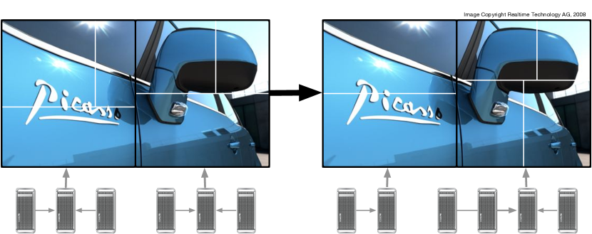
The output channels each drive a display or projector of a multi-display system. Commonly, each destination channel is solely responsible for rendering and potentially compositing of its corresponding display segment.
A key element of CSLB is that the GPUs physically driving the display segments are not restricted to a one-to-one mapping of rendering tasks to the corresponding display segment. CSLB performs a dynamic assignment of graphics resources from a pool to drive different destination display segments, where the destination channel GPUs themselves may also be part of the pool of graphics resources. CSLB also does not require a planar display surface, that is, the algorithm works equally for tiled display walls and immersive installations.
Dynamic resource assignment is performed through load balancing components that exploit statistical data from previous frames for the decision of optimal GPU usage for each segment, as well as optimal distribution of work among them. The algorithm is also compatible with predictive load balancing based on a load estimation given by the application.
CSLB is implemented in Equalizer as two layers of hierarchically organised components specified in the configuration. The first level globally assigns fractions of resources to each destination channel, and the second level consist of load_equalizers or tree_equalizers balancing the assigned resources for each destination segment.
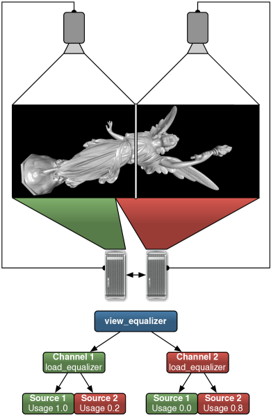
compound
{
view_equalizer {}
compound
{
channel "Channel1"
load_equalizer{}
compound {} # self
compound
{
channel "Source2"
outputframe {}
}
inputframe{}
...
}
compound
{
channel "Channel2"
load_equalizer{}
compound {} # self
compound
{
channel "Source1"
outputframe {}
}
inputframe{}
}
...
}
Figure 6.3 depicts a snapshot of the simplest CSLB setup along with its configuration file. Two destination channels, Channel1 and Channel2, each connected to a projector, create the final output for a multi-projector view. Each projector is driven by a distinct GPU, constituting the source channels Source1 and Source2. Each source channel GPU can contribute to the rendering of the other destination channel segment. For each destination channel, a set of potential resources are allocated. A top-level view_equalizer assigns the usage to each resource, based on which per-segment load_equalizers compute the 2D split to balance the assigned resources within the display. The left segment of the display has a higher workload, so, both Source1 and Source2 are used to render for Channel1, whereas Channel2 uses only Source2 to render the image for the right segment. The schematic also shows the current usage of the four potential source compounds, where only three have an active draw pass at this point in time.
CSLB uses a two-stage approach, where a view_equalizer at the top level of the compound hierarchy handles the resource assignment. Each child of this root compound has one destination (segment) channel, corresponding to one of the display segments, using a load_equalizer or tree_equalizer. The view equalizer supervises the different destination channels of a multi-display setup; the load equalizers on the other hand are responsible for the partitioning of the rendering task of each segment among its child compounds. They use the precomputed usage of each child to allocate a corresponding amount of work for the child. Therefore, each destination channel of a display segment has its source channel leaf nodes sharing the actual rendering load. One physical GPU assigned to a source channel can be referenced in multiple leaf nodes, and thus contribute to different displays.
For performance reasons the view equalizer assigns each resource to at most two rendering tasks, e.g., to update itself and to contribute to another display. Furthermore, it gives priority to the source compound using the same channel as the output channel of each segment to minimise pixel transfers.
Cross-segment load balancing allows for optimal resource usage of multiple GPUs used for driving the display segments themselves, as well as any additional source GPUs for rendering. It combines multi-display parallel rendering with scalable rendering for optimal performance.
benchmarkO.618
![[Uncaptioned image]](/html/1902.08755/assets/x47.png) Cross-Segment Load Balancing
Cross-Segment Load Balancing
[Erol et al., 2011] provides experimental results for a six-monitor tiled display wall, driven by twelve GPUs. Benchmark 6.3 shows an overview for the achievable performance improvements. The first two configurations use a static assignment of two GPUs to one output channel, where the first one statically assigns one half to each GPU, and the second uses a load balancer to dynamically split the work between the two GPUs. Already this 2D load balancing improves the framerate by almost 50%. The remaining configurations add a view equalizer on top of the per-segment 2D load equalizer. The configuration assigns up to 4, 6, 8, 10 or all GPUs to each segment, that is, any segment may use up to GPUs, and the GPUs are shared evenly across multiple segments. While theoretically the all-to-all () configuration should provide the best performance, mispredictions of the equalizers lead to a sweet spot of GPU sharing between segments. In our setup, assigning up to six GPUs per segment almost doubles the performance over the state-of-the-art sort-first load balanced setup.
Benchmark 6.f shows the rendering time over a fixed camera path of 540 frames. In the static case two GPUs are responsible for each of the six outputs of the tiled display wall used. For the CSLB graph, up to eight GPUs were dynamically reassigned each frame to each of the six output channels, depending on the current load distribution. Except for a few camera positions, where the model is positioned evenly over all outputs, CSLB outperforms the fixed assignment.
![[Uncaptioned image]](/html/1902.08755/assets/x48.png)
A strength of this algorithm lies in its flexibility. On one hand, it can perform dynamic resource assignment not only for a planar display system, as some approaches which built a single virtual framebuffer, but also for curved displays and CAVE installations. On the other hand, it allows a flexible assignment of potential contributing GPUs to each output channel individually. Each output may have a different, potentially overlapping, set of GPUs which may contribute to its rendering.
6.4 Dynamic Frame Resolution
Dynamic Frame Resolution (DFR) (Figure 6.4) provides a functionality similar to dynamic video resizing [Montrym et al., 1997], specifically it maintains a constant framerate by adapting the rendering resolution of a fill-limited application.
figureO.618
![[Uncaptioned image]](/html/1902.08755/assets/images/dfr.png) Dynamic Frame Resolution
Dynamic Frame Resolution
While the aforementioned uses a now-obsolete hardware implementation, our implementation works on commodity hardware and is purely implemented in software.
DFR works by rendering into a source channel (often on a FBO) separate from the destination channel, and then scaling the rendering during the transfer (typically through an on-GPU texture) to the destination channel. The DFR equalizer monitors the rendering performance and accordingly adapts the resolution of the source channel and the zoom factor for the source to destination transfer. If the performance and source channel resolutions allow, this will not only subsample, but also supersample the destination channel to reduce aliasing artefacts.
DFR can be combined with other scalability features, e.g., sort-first rendering. It is also notable that it does not need any additional code in the core compound logic, it simply exploits existing functionality such as texture-based compositing frames and frame zoom with dynamic per-frame adjustments.
6.5 Frame Rate Equalizer
The framerate equalizer smooths the output frame rate of a destination channel by instructing the corresponding window to delay its buffer swap to a minimum time between swaps. This is regularly used for time-multiplexed decompositions, where source channels tend to drift and finish their rendering unevenly distributed over time. This equalizer is however fully independent of DPlex compounds, and may be used to smooth the framerate of irregular rendering algorithms. Due to the artificial sleep time before swap, it may incur a small performance penalty, but it greatly improves the perceived rendering quality for users in DPlex compounds.
6.6 Monitoring
The monitor equalizer (Figure 6.6) allows reusing of the rendering from one or more channels on another channel, typically for monitoring a larger display setup on a control workstation.
figureO.618
![[Uncaptioned image]](/html/1902.08755/assets/images/monitoreq.png) Monitoring
Monitoring
Output frames on the display channels are connected to input frames on the monitoring channel. The monitor equalizer changes the scaling factor and offset between the output and input, so that the monitor channel has the same, but typically downscaled view, as the originating segments. While this is not strictly a scalable rendering feature, it optimises resource usage by not needlessly rendering the same view multiple times. It reuses the zoom parameter of compositing frames, and adapts this every time one of the channels is resized.
Chapter 7 Data Distribution and Synchronisation
7.1 Overview
Most research in parallel rendering does not look into the problem of managing application state in a distributed rendering session. For basic parallel rendering research this problem is trivial to solve, whereas in real-world applications it is often one of the major challenges for using a distributed rendering cluster. Researching and improving the system behaviour of non-trivial applications is critical for meaningful parallel rendering research, and therefore providing a distributed network library is a key component of a parallel rendering system.
For this reason we have spend significant effort in researching, designing and implementing a distributed execution layer used by Equalizer and applications built on Equalizer. The Collage network library is an independent open source project. In the following sections we highlight core features and show how they are different from other distribution mechanisms, e.g., the MPI library.
The Collage network library was conceived with the requirements of a dynamic parallel rendering system in mind. Some of the features implemented by Collage emerged with the growing complexity of Equalizer and its applications, and are often layered on top of the basic primitives. The core requirements are:
- Peer-to-peer network:
-
Whilst the execution model of an Equalizer application follows a master-slave approach, and Equalizer internally uses a client-server model, the core transport layer should be agnostic to these higher-level abstractions. In Collage, each communicating process is equal to all others, and no traffic prioritisation or communication pattern is enforced by a node type. This has proven particularly useful during the implementation of parallel compositing algorithms, where the compositing nodes form an ad-hoc peer-to-peer sub-network.
- Dynamic connection management:
-
As a consequence of the peer-to-peer network, all nodes in a cluster are equivalent. Due to the heterogeneous nature of a parallel rendering application, we furthermore imposed no constraints on the management of connections between nodes. Nodes are identified and addressed by an universally unique identifier. The network layer lazily establishes a connection to any given node by querying its known neighbours or a zeroconf network for connection parameters. Connections may be established concurrently by both sides of a node pair (e.g. during parallel compositing), which requires a robust handshake protocol during connection establishment. For larger cluster installations, a fully connected peer-to-peer network would be suboptimal. For example on Windows operating systems there is a latency penalty once more than 64 connections are needed, caused by low-level implementation details. This feature also allowed us to implement runtime configuration switches involving a changing set of rendering resources.
- Transport layer abstraction:
-
The actual network protocol is abstracted by an API defining byte-oriented stream semantics. While this choice of abstraction makes it harder for RDMA-based protocols to deliver full performance, it has proven useful in supporting a large set of transports, from standard Ethernet sockets, SDP for InfiniBand, native Verbs for InfiniBand, UDT to a fully-featured reliable multicast implementation. In particular, the ease of integration of multicast transport is strong evidence for the usefulness of this abstraction.
- Convenient to use for existing applications:
-
The history and code structure of visualisation applications is often very different from other distributed applications, such as simulation codes. They have been developed for years for desktop systems, are often single-threaded and have data models and object hierarchies built for their domain-specific problems and algorithms. The network library needs to provide primitives which match this reality as closely as possible by providing a modern, object-oriented C++ API.
7.2 Architecture
Our Collage network library provides a peer-to-peer communication infrastructure, offering different abstraction layers which gradually provide higher level functionality to the programmer. Collage is used by Equalizer to communicate between the application node, the server and the render clients. Many resource entities described in Chapter 3 are distributed Collage objects. Figure 7.1 provides an overview of the major Collage classes and their relationship. The main classes, in ascending abstraction level, are:
- Connection:
-
A stream-oriented point-to-point communication line. Different implementations of a connection exist. A connection transmits a raw byte stream reliably between two endpoints for unicast connections, and between a set of endpoints for multicast connections.
- DataOStream:
-
Abstracts the output of C++ data types onto a set of connections by implementing output stream operators. Uses buffering to aggregate data for network transmission.
- OCommand:
-
Extends DataOStream to implement the protocol between Collage nodes by adding node and command type routing information to the stream.
- DataIStream:
-
Decodes a buffer of received data into C++ objects and PODs by implementing input stream operators. Performs endian swapping if the endianness differs between the originating and local node.
- ICommand:
-
The other side of OCommand, extending DataIStream.
- Node and LocalNode:
-
The abstraction of a process in the cluster. Nodes communicate with each other using connections. A LocalNode listens on various connections and processes requests for a given process. Received data is wrapped in ICommands and dispatched to command handler methods. A Node is a proxy for communicating with a remote LocalNode.
- Object:
-
Provides object-oriented, versioned data distribution of C++ objects between nodes within a session. Objects are registered or mapped on a LocalNode.
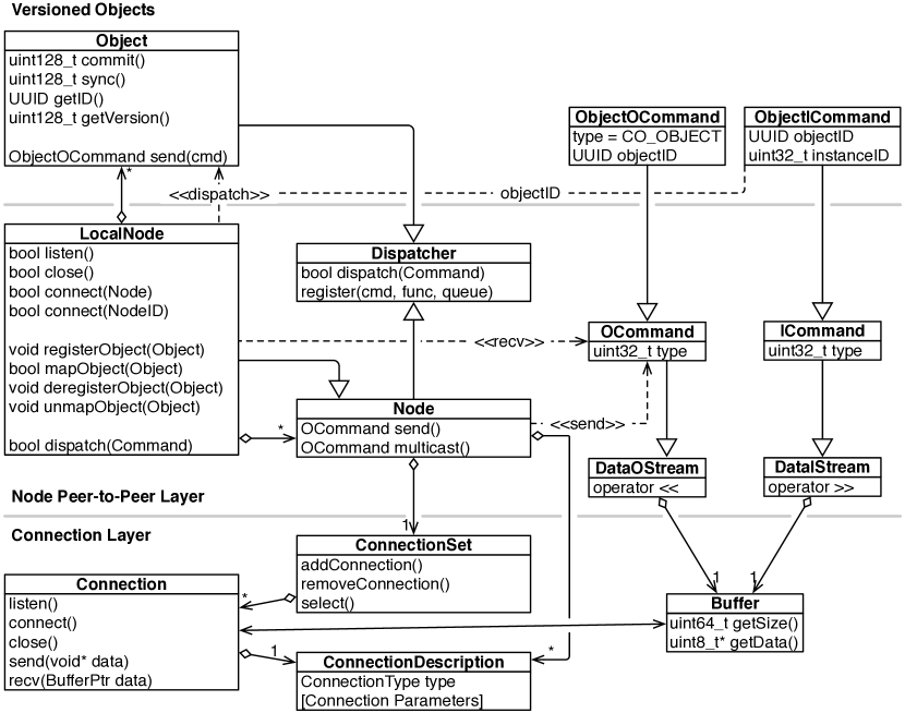
7.2.1 Connection
A Connection is the basic primitive used for communication between processes in Collage. It provides a stream-oriented communication between two endpoints. A connection is either closed, connected or listening. A closed connection cannot be used for communication. A connected connection can be used to read or write data to the communication peer. A listening connection can accept connection requests leading to new, connected connections.
A ConnectionSet is used to manage multiple connections. The typical use case is to have one or more listening connections for the local process, and a number of connected connections for communicating with other processes. The connection set is used to select one connection requiring some action. This can be a connection request on a listening connection, pending data on a connected connection, or the notification of a disconnect. It is an encapsulation of the poll or WaitForMultipleObject system calls.
The connection and connection set can be used by applications to implement other network-related functionality, e.g., to communicate with a sound server on a different machine. They do not require a particular wire protocol. A LocalNode has a connection set and uses it to manage connections with other nodes.
7.2.2 Data Streams
Data streams implement serialisation and buffering on top of connections. They use output and input stream operators (<< and >>) with function overloads to provide serialisation for all common data types. The input stream will perform byte swapping if the endianness differs between the sending and receiving node. Applications can easily provide overloads for their own classes for serialisation. All serialised data is assembled in a memory buffer and sent over the connection once the data is complete. An output data stream might send its data to many connections, e.g., when an object update is sent to all subscribed slave nodes.
7.2.3 Thread-aware Command Dispatch
Collage sends commands over connections to implement remote procedure calls. A command is identified by its type (typically the C++ class handling it) and a command identifier. These fields are used to implement thread-aware dispatching of received commands to handler functions.
Nodes and objects communicate using commands derived from data streams. The basic command dispatch is implemented in the Dispatcher class, from which Node and Object are sub-classed.
The dispatcher allows the registration of commands with a dispatch queue and an invocation method. Each command has a type and command identifier, which is used to identify the receiver, registered queue and method. The dispatch pushes the packet to the registered queue. When the commands are dequeued by the processing thread, the registered command method is invoked.
This dispatch and invocation functionality is used within Equalizer to dispatch commands from the receiver thread to the appropriate node or pipe thread, and then to call a specific method when it is processed by these threads. All Equalizer task methods available to the application are triggered by this mechanism. This dispatch provides object-oriented semantics, since C++ instances can register themselves on the dispatcher, and get automatically invoked in the correct thread when an appropriate command arrives.
7.2.4 Nodes
The Node is the abstraction of one process in the peer-to-peer network. Each node has a universally unique identifier. This identifier is used to address nodes, e.g., to query connection information to connect to the node. Nodes use connections to communicate with each other by sending OCommands.
The LocalNode is the specialisation of the node for the given process. It encapsulates the communication logic for connecting remote nodes, as well as object registration and mapping. Local nodes are set up in the listening state during initialisation.
A remote Node can either be connected explicitly by the application, or implicitly due to a connection from a remote node. The explicit connection can be done by programmatically creating a node, adding the necessary ConnectionDescriptions and connecting it to the local node. It may also be done by connecting the remote node to the local node by using its NodeID. This will cause Collage to query connection information for this node from the already connected nodes and zeroconf, instantiating the node and connecting it. Both operations may fail.
Each Equalizer entity has a LocalNode for communication, and one Node instance for each peer it communicates with.
Zeroconf Discovery
Each LocalNode provides a Zeroconf communicator, which allows node and resource discovery. The zeroconf service ”_collage._tcp” is used to announce the presence of a listening LocalNode using the ZeroConf protocol to the network. The node identifier and all listening connection descriptions are announced, used to connect unknown nodes by using the node identifier alone.
Communication between Nodes
Figure 7.2 shows the communication between two nodes. Each LocalNode has a receiver thread, which uses a connection set to read and dispatch incoming data from the network, and a command thread used for higher-level functions such as object mapping. When the remote node sends a command, the listening node receives the command and dispatches it from the receiver thread. The dispatch will either invoke the bound function immediately, or enqueue the command into the given queue. The queue consumer, for example the main or command thread, will read the command of this queue and then invoke the bound function.
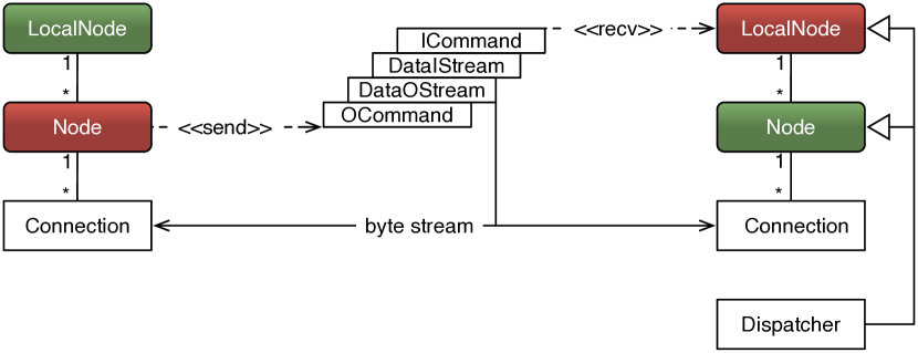
7.3 Reliable Stream Protocol
RSP is an implementation of a reliable multicast protocol over unreliable UDP multicast transport. RSP behaves similarly to TCP; in contrast to the underlying UDP transport, it is not message-oriented, but implements byte stream semantics. RSP provides full reliability and ordering of the data, and slow receivers will eventually throttle the sender through a sliding window algorithm. This behaviour is needed to guarantee delivery of data in all situations. Pragmatic generic multicast (PGM [Gemmell et al., 2003]) provides full ordering, but slow clients will disconnect from the multicast session instead of throttling the send rate. Since we use multicast for distributing application data to all rendering clients, we want semantics similar to TCP, expressly waiting for a client to read data is preferable over losing this client.
RSP combines various established multicast algorithms [Adamson et al., 2004, Gau et al., 2002] in an open source implementation capable of delivering wire speed transmission rates on high-speed LAN interfaces. The following will outline the RSP protocol and implementation, as well as the motivation for the design decisions. Any defaults given below are for Linux or Mac OS X, the Windows UDP stack requires different default values which can be found in the implementation.
Our RSP implementation uses a separate protocol thread for each RSP group, which handles all reads and writes on the multicast UDP socket. It implements the protocol handling and communicates with the application threads through thread-safe queues. The queues contain datagrams filled with the application byte stream, prefixed by a header of at most eight bytes. Each connection has a configurable number of buffers (1024 by default) of a configurable datagram size (1470 bytes default), which are either free or in transmission. The header contains two bytes for the datagram type (connection handshake, data, acknowledgement, negative acknowledgement, acknowledgement request), and up two six bytes of datagram-specific information (e.g. for acknowledgement: two bytes read node identifier, two bytes write node identifier, two bytes sequence number).
Figure 7.3 shows the data flow through the RSP implementation. Each member of the multicast group opens a listening connection, which will send query datagrams to the multicast socket. For each found member, a receiving connection instance is created and, similar to a TCP socket, passed to the application upon accept. Each connection instance has a fixed number (1024 by default) of fixed-size (1470 by default) buffers, each used directly for an UDP datagram. The listening connection uses these buffers for writing data, and each receiving connection uses its buffers for received data. These buffers are continuously cycled through two sets of queues: a blocking, thread-safe queue used on the application side for reading and writing data, and a non-blocking, lock-free and thread-safe queue on the protocol thread for data management.
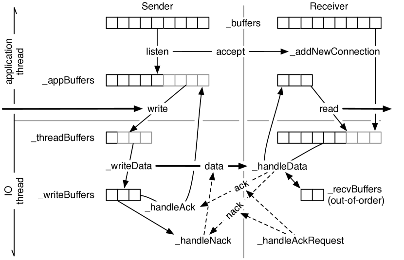
When writing data, the application thread pops empty buffers from its queue (blocking when the data cannot be written fast enough), fills in the data datagram header and copies the application data piece-wise into the datagram. The datagrams are then pushed onto the protocol thread buffer queue. The protocol thread writes the datagrams into the UDP multicast socket, and reads and handles any incoming datagrams. On the receiver side, the protocol receives the data, and pushes them in order to the corresponding application thread queue. Out-of-order datagrams are stored aside and queued in order later. Negative acknowledgements (nack) are immediately sent for missing datagrams. The writer will repeat nack’d datagrams, recycle fully acknowledged datagrams to the application queue, and ask for missing acknowledgements if needed. When reading data, the application pops full buffers from the corresponding connection queue (blocking when no data is available), copies the data piece-wise out of the datagram into the application buffer, and recycles the cleared buffers onto the protocol thread queue.
Handling a smooth packet flow is critical for performance. RSP uses active flow control to advance the byte stream buffered by the implementation. Each incoming connection actively acknowledges every (17 by default) packets fully received. The incoming connection offset this acknowledgement by their connection identifier to avoid ack bursts. Any missed datagram is actively nack’d as soon as detected. Write connections continuously retransmit packets for nack datagrams, and advance their window upon reception of all acks from the group. The writer will explicitly request an ack or nack when it runs out of empty buffers or finishes its write queue. Nack datagrams may contain multiple ranges of missed datagrams, motivated by the observation that UDP implementations often drop multiple contiguous packets.
Congestion control is necessary to optimise bandwidth usage. While TCP uses the well-known additive increase, multiplicative decrease algorithm, we have chosen a more aggressive congestion control algorithm of additive increase and additive decrease. Experimentally this has proven to be more optimal: UDP is often rate-limited by switches; packets are discarded regularly and not occasionally. Only slowly backing off the current send rate helps to stay close to this limit. Furthermore, our RSP traffic is limited to the local subnet, making cooperation between multiple data stream less of an issue. Send rate limiting uses a bucket algorithm, where over time the bucket fills with send credits, from which send datagrams are subtracted. If there are no available credits, the sender sleeps until sufficient credits are available.
In [Eilemann et al., 2018] we provide experimental results showing that our implementation can achieve above 90% wire speed on 10 GBit/s Ethernet, good scalability with respect to multicast group size, and is very effective for concurrently distributing structured and unstructured application data to a large number of rendering clients (see Benchmark 7.4.5).
7.4 Distributed, Versioned Objects
7.4.1 Overview
Adapting an existing application for parallel rendering requires the synchronisation of application data across the processes in the parallel rendering setup. Existing parallel rendering frameworks often address this poorly, at best they rely on MPI to distribute data. Real-world, interactive visualisation applications are typically written in C++ and have complex data models and class hierarchies to represent their application state. As outlined in [Eilemann et al., 2009], the parallel rendering code in an Equalizer application only requires access to the data needed for rendering, as all application logic is centralised in the application main thread. We have encountered two main approaches to address this distribution: Using a shared filesystem for static data, or using data distribution for static and dynamic data. Distributed objects are not required to build Equalizer applications. While most developers choose to use this abstraction for convenience, we have seen applications using other means for data distribution, e.g., MPI.
7.4.2 Object Types
Distributed objects in Collage provide powerful, object-oriented data distribution for C++ objects. They facilitate the implementation of data distribution in a cluster environment. Distributed objects are created by subclassing from co::Serializable or co::Object. The application programmer implements serialisation and deserialisation. Distributed objects can be static (immutable) or dynamic. Objects have a universally unique identifier (UUID) as cluster-wide address. A master-slave model is used to establish mapping and data synchronisation across processes. Typically, the application main loop registers a master instance and communicates the UUID to the render clients, which map their instance to the given identifier. The following object types are available:
- Static
-
The object is neither versioned nor buffered. The instance data is serialised whenever a new slave instance is mapped. No additional data is stored.
- Unbuffered
-
The object is versioned and unbuffered. No data is stored, and no previous versions can be mapped.
- Instance
-
The object is versioned and buffered. The instance and delta data are identical; that is, only instance data is serialised. Previous instance data is saved to be able to map old versions.
- Delta
-
The object is versioned and buffered. The delta data is typically smaller than the instance data. The delta data is transmitted to slave instances for synchronisation. Previous instance and delta data is saved to be able to map and sync old versions.
Instance and delta objects have a memory overhead on the master instance to store past data. The number of old versions retained is configurable per object. For Equalizer applications, this overhead typically occurs on the application node holding the master instances, and is configured based on the configurations’ latency. When using unbuffered objects, applications only observe inconsistent state during the initial mapping, when a too recent version is used by a render client. The push-based commit-sync logic eventually brings the object into a consistent state with respect to the rendered frame.
Serialisation is facilitated using output or input streams, which abstract the data transmission and are used like a std::stream. The data streams implement efficient buffering and compression, and automatically select the best connection for data transport. Custom data type serialisers can be implemented by providing the appropriate serialisation functions. No pointers should be directly transmitted through the data streams. For pointers, the corresponding object is typically also a distributed object , and its UUID and version are transmitted in lieu of a pointer.
Dynamic objects are versioned, and on commit the delta data to the previous version is sent, if available using multicast, to all mapped slave instances. The data is queued on the remote node, and is applied when the application calls sync to synchronise the object to a new version. The sync method might block if a version has not yet been committed or is still in transmission. All versioned objects have the following characteristics:
-
•
The master instance of the object generates new versions for all slaves. These versions are continuous. It is possible to commit on slave instances, but special care has to be taken to handle possible conflicts during concurrent commits from multiple slave instances.
-
•
Slave instance versions can only be advanced; that is, sync(version) with a version older than the current version will fail.
-
•
Newly mapped slave instances are mapped to the oldest available version by default, or to the version specified when calling mapObject.
Blocking commits allows limiting the number of outstanding, queued versions on the slave nodes. A token-based protocol will block the commit on the master instance if too many unsynchronised versions exist. This is useful to limit the amount of memory consumed by slave instance, and too prohibit run-away conditions of the master instance.
7.4.3 Serialisable
The Serializable implements one convenient usage pattern for object data distribution which emerged during deployment of Equalizer in applications. The Serializable data distribution is based on the concept of dirty bits, allowing inheritance with data distribution. Dirty bits are a 64-bit mask tracking the parts of the object to be distributed during the next commit. Setters of the class mark the appropriate dirty bit, and the accumulated bits are used to compute deltas during commit.
For serialization, the application developer implements serialize or deserialize, which are called with the bit mask specifying which data has to be transmitted or received. During a commit or sync, the current dirty bits are given, whereas during object mapping all dirty bits are passed to the serialisation methods. A commit will clear the dirty mask after serialisation.
7.4.4 Optimisations
The Object API provides sufficient abstraction to implement various optimisations for faster mapping and synchronisation of data: compression, chunking, caching, preloading and multicast.
Compression
The most obvious optimisation is compression. Recently many new compression algorithms have been developed, exploiting modern CPU architectures and deliver compression rates well above one Gigabyte per second. Collage uses the Pression library [Eyescale Software GmbH and Blue Brain Project, 2016], which provides an unified interface for a number of compression libraries, such as FastLZ [Hidayat, 2007], Snappy [opensource@google.com, 2016] and ZStandard [Facebook, 2016]. It also contains a custom, virtually zero-cost RLE compressor. Pression parallelises the compression and decompression using data decomposition. The compression is generic and lossless, available transparently to the application. Applications can also use data-specific compression.
Benchmark 7.g (top left) shows the compression ratio and speed for generic binary data from [Eilemann et al., 2018]. Whilst the structure of the transmitted data varies with each application, this micro-benchmark gives a reasonable estimation of the expected performance. In our context of interactive distributed rendering applications, it is important to use the right tradeoff between spending time and resources for data compression, and the gained network transmission time due data reduction.
![[Uncaptioned image]](/html/1902.08755/assets/x52.png)
On current CPUs (the benchmark was executed on a 12-core node), modern compression libraries provide performance benefits even on fast interconnects such as 10 Gb/s Ethernet. In particular, the modern Snappy and ZStandard libraries deliver impressive performance.
In [Eilemann et al., 2018] we also evaluated the compression performance for concrete application data. The results are shown in Benchmark 7.g. Polygonal data is difficult to compress with a generic lossless compressor, due to the floating point format used for the vertices. A data-specific compressor aware of the data semantics can provide much better results. Volume data on the other hand has shown to be well compressible, with typical compression ratios at interactive speeds. Section 7.4.5 discusses how these compressors accelerate data distribution in Equalizer applications.
Chunking
The data streaming interface implements chunking, which pipelines the serialisation code with the network transmission. After a configurable number of bytes has been serialised to the internal buffer, it is transmitted and serialisation continues. This is used both for the initial mapping data, and for commit data.
Caching and Preloading
Caching retains instance data of objects in a client-side cache, and reuses this data to accelerate mapping of objects. The instance cache is either filled by “snooping” on multicast transmissions or by an explicit preloading when master objects are registered. Preloading sends instance data of recently registered master objects to all connected nodes during idle time of the corresponding node. These nodes simply enter the received data to their cache. Preloading uses multicast when available.
Multicast
Due to the master-slave nature of data distribution, multicast is used to optimise the transmission time of data. If the contributing nodes share a multicast session, and more than one slave instance is mapped, Collage automatically uses the multicast connection to send the new version information.
7.4.5 Benchmarks
Benchmark 7.h analyses the performance of data distribution and synchronisation in real-world applications. We extracted the data distribution code from our mesh renderer (eqPly) and our volume renderer (Livre) into a benchmark application to measure the time to initially map all the objects on the render client nodes, and to perform a commitsync of the full data set after mapping has been established. All figures observe a noticeable measurement jitter due to other services running on the shared cluster during benchmarking. The details of the benchmark algorithm can be found in [Eilemann et al., 2018].
![[Uncaptioned image]](/html/1902.08755/assets/x53.png)
We used three different data sets, and ran the benchmark on up to eight physical nodes, specifically, after eight process nodes start to run two processes per node, which share CPU, memory and network interface bandwidth. Object mapping is measured using the following settings: none distributes the raw, uncompressed, and unbuffered data, compression uses the Snappy compressor to compress and distribute unbuffered data, buffered reuses uncompressed, serialised data for mappings from multiple nodes, and compression buffered reuses the compressed buffer for multiple nodes.
Unbuffered operations need to reserialise, and potentially recompress, the master object data for each slave node. Each slave instance needs to deserialise and decompress the data, which happens naturally in parallel on the slave nodes. During data synchronisation, the master commits the object data to all mapped slave instances simultaneously. This is a “push” operation, whereas the mapping is a slave-triggered “pull” operation. During commit, the buffers only have to be serialised and compressed once, and can then be sent directly to all mapped slave nodes. Slave nodes queue this data and consume it during synchronisation. In contrast, object mapping needs to wait for each slave node to request the mapping, and then may need to reserialise and compress the object data. We tested the time to commit and sync the data using the compression engines discussed above.
The David statue at a 2 mm resolution is organised in a k-d tree for rendering. Each k-d tree node is a separate distributed object, having two child node objects. A total of 1023 objects are distributed and synchronised. Due to limited compressibility of the data, the results are relatively similar. Compressing the data repeatedly for each client leads to decreased performance, since the compression overhead cannot be amortised by a decreased transmission time. Buffering data slightly improves performance by reducing the CPU and copy overhead. Combining compression and buffering leads to the best performance, although only by about 10%. During synchronisation data is pushed from the master process to all mapped slaves using a unicast connection to each slave. While the results are relatively close to each other, we can still observe how the tradeoff between compression ratio and speed influences overall performance. Better, slower compression algorithms lead to improved overall performance when amortised over many send operations.
The volume data sets are distributed in a single object, serialising the raw volume buffer. The Spike volume data set has a significant compression ratio, which is reflected by the results. Compression for this data is beneficial for transmitting data over a 10 Gb/s link, even for a single slave process. Buffering has little benefit, since the serialisation of volume data is trivial. Buffered compression shows a significant difference, since the compression cost can be amortised over many nodes, reaching raw data transmission rates of 3.7 GB/s with the default Snappy compressor, and at best 4.4 GB/s with ZStandard at level 1. The distribution of the beechnut data set also behaves as expected: Due to the larger object size, uncompressed transmission is slightly faster compared to the Spike data set at 700 MB/s since static overheads are comparatively smaller. Compressed transmission does not improve the mapping performance, likely due to increased memory pressure caused by the data size. The comparison of the various compression engines is consistent with the benchmarks in Benchmark 7.g; RLE, Snappy and the LZ variants are very close to each other, and ZSTD1 can provide better performance after four nodes due to the better compression ratio.
benchmarkO.618
![[Uncaptioned image]](/html/1902.08755/assets/x54.png) Synchronisation Performance over different Network Protocols
Synchronisation Performance over different Network Protocols
Benchmark 7.4.5 compares data distribution speed using different network protocols. This benchmark measures the data synchronisation time of the Spike volume data set. Buffering is enabled, and compression is disabled to focus on the raw network performance. For the benchmark, eight physical nodes are used, that is, after eight processes two client processes will run on some nodes, sharing CPU and network resources.
TCP over the faster InfiniBand link outperforms the cheaper Ten Gigabit Ethernet link by more than a factor of two. Unexpectedly, the native RDMA connection performs worse, even though it outperforms IPoIB in a simple peer-to-peer connection benchmark. This needs further investigation, but we suspect the abstraction of a byte stream connection chosen by Collage is not well suited for remote DMA semantics; one needs to design the network API around zero-copy semantics with managed memory for modern high-speed transports. Both InfiniBand connections show significant measurement jitter.
RSP multicast performs as expected. Collage starts using multicast to commit new object versions when two or more clients are mapped, since the transmission to a single client is faster using unicast. RSP consistently outperforms unicast on the same physical interface and shows good scaling behaviour (2.5 times slower on 16 vs. 2 clients on Ethernet, 1.8 times slower on InfiniBand). The scaling is significantly better when only one process per node is used. The increased transmission time with multiple clients is caused by a higher probability of packet loss, which increases significantly when using more than one process per node and network interface. InfiniBand outperforms Ethernet slightly, but is largely limited by the RSP implementation throughput of preparing and queueing the datagrams to and from the protocol thread, which we observed in profiling.
Chapter 8 Applications
A key performance indicator for a good design of any framework is the acceptance by developers. A good measure is the adoption by third-party applications. While the evaluation and architecture of applications build with Equalizer is outside of the scope of this thesis, we provide a few examples here to illustrate the variety of use cases supported in our framework.
8.1 Livre
figureO.618
![[Uncaptioned image]](/html/1902.08755/assets/images/livre.png) Livre running on a 4x3 Tiled Display Wall
Livre running on a 4x3 Tiled Display Wall
Livre (Large-scale Interactive Volume Rendering Engine) is a GPU ray-casting parallel 4D volume renderer, implementing state-of-the-art view-dependent level-of-detail rendering (LOD) and out-of-core data management [Engel et al., 2006].
Hierarchical and out-of-core LOD data management is supported by an implicit volume octree, accessed asynchronously by the renderer from a data source on a shared file system. Different data sources provide octree-conform access to RAW or compressed files, as well as to on-the-fly generated volume data (e.g. such as from event simulations or surface meshes).
High-level state information, e.g., camera position and rendering settings, are shared in Livre through Collage objects between the application and rendering threads. Sort-first decomposition is efficiently supported through octree traversal and culling, both for scalability, as well as for driving large-scale tiled display walls.
8.2 RTT Deltagen
RTT Deltagen (now Dassault 3D Excite) is a commercial application for interactive, high quality rendering of CAD data. The RTT Scale module, delivering multi-GPU and distributed execution, is based on Equalizer and Collage, and has driven many of the features implemented in Equalizer.
figureO.618
![[Uncaptioned image]](/html/1902.08755/assets/images/DeltaGen.jpg) RTT Deltagen mixing OpenGL Rendering and Raytracing (for the head light)
RTT Deltagen mixing OpenGL Rendering and Raytracing (for the head light)
RTT Scale uses a master-slave execution mode, were a single Deltagen instance can go into “Scale mode” at any time by launching an Equalizer configuration. Consequently, the internal representation needed for rendering is based on a Collage-based data distribution. The rendering clients are separate, smaller applications which will map their scenes during startup. At runtime any change performed in the main application is committed as a delta at the beginning of the next frame. Multicast is used to keep data distribution times during session launch reasonable for larger cluster sizes (tens to hundreds of nodes).
RTT Scale supports a wide variety of use cases. In virtual reality, the application is used for virtual prototyping and design reviews in front of high-resolution display walls and CAVEs. It is also used for virtual prototyping of human-machine interactions in CAVEs and HMDs. For scalability, sort-first and tile compounds are used to achieve fast, high-quality rendering, primarily for interactive raytracing, both based on CPUs and GPUs. For CPU-based raytracing, often Linux-based rendering clients are used with a Windows-based application node.
8.3 RTNeuron
figureO.618
![[Uncaptioned image]](/html/1902.08755/assets/images/RTNeuron.jpg) RTNeuron running in a six-sided CAVE
RTNeuron running in a six-sided CAVE
RTNeuron [Hernando et al., 2013] is a scalable real-time rendering tool for the visualisation of neuronal simulations based on cable models. It uses OpenSceneGraph for data management and Equalizer for parallel rendering. The focus is not only on fast rendering times, but also on fast loading times with no offline preprocessing. It provides level of detail (LOD) rendering, high quality anti-aliasing based on jittered frusta, accumulation during still views, and interactive modification of the visual representation of neurons on a per-neuron basis (full neuron vs. soma only, branch pruning depending on the branch level, …). RTNeuron implements both sort-first and sort-last rendering with order independent transparency.
8.4 RASTeR
figureO.618
![[Uncaptioned image]](/html/1902.08755/assets/images/raster.jpg) RASTeR running on a 3x2 Tiled Display Wall
RASTeR running on a 3x2 Tiled Display Wall
RASTeR [Bösch et al., 2009] uses an out-of-core and view-dependent real-time multi-resolution terrain rendering algorithm. For load balanced parallel rendering [Goswami et al., 2010] it exploits fast hierarchical view-frustum culling of the level-of-detail (LOD) quadtree for sort-first decomposition, and uniform distribution of the visible LOD triangle patches for sort-last decomposition. The latter is enabled by a fast traversal of the patch-based restricted quadtree triangulation hierarchy, which results in a list of selected LOD nodes, constituting a view-dependent cut or front of activated nodes through the LOD hierarchy. Assigning and distributing equally sized segments of this active LOD front to the concurrent rendering threads results in a near-optimal sort-last decomposition for each frame.
8.5 Bino
figureO.618
![[Uncaptioned image]](/html/1902.08755/assets/images/bino.jpg) Bino on a Semi-Cylindrical Multi-Projector Wall
Bino on a Semi-Cylindrical Multi-Projector Wall
Bino is a stereoscopic 3D video player capable of running on very large display systems. Originally written for the immersive semi-cylindrical projection system at the University of Siegen, its flexibility enabled its use in many installations. Bino decodes video on each rendering thread and only synchronises the time step globally, providing a scalable solution to video playback. Bino uses the 2D information from the segment viewports to lay out the video tiles for each projector.
8.6 Omegalib
figureO.618
![[Uncaptioned image]](/html/1902.08755/assets/images/omegalib.jpg) An Omegalib Application running in the Cave2
An Omegalib Application running in the Cave2
Omegalib [Febretti et al., 2014] is a software framework built on top of Equalizer that facilitates application development for hybrid reality environments, like the Cave 2. Hybrid reality environments aim to create a seamless 2D/3D environment supporting both information-rich analysis (traditionally done on tiled display wall), as well as virtual reality simulation exploration (traditionally done in VR systems) at a resolution matching human visual acuity. Omegalib supports dynamic reconfigurability of the display environment, so that areas of the display can be interactively allocated to 2D or 3D workspaces as needed. It is possible to have multiple immersive applications running on a cluster-controlled display system, have different input sources dynamically routed to applications, and have rendering results optionally redirected to a distributed compositing manager. Omegalib supports pluggable front-ends to simplify the integration of third-party libraries like OpenGL, OpenSceneGraph, and the Visualisation Toolkit (VTK).
Chapter 9 Conclusion
9.1 Summary
Formalising, designing and implementing a generic parallel rendering framework, that can serve both complex applications and research, has been no easy task. Based on the analysis of Cavelib, practical experience in implementing and deploying OpenGL Multipipe SDK, we have been in the unique position to make significant contributions in this area. Equalizer, our parallel rendering framework, allowed us to take parallel rendering research to a new level. It enabled us to easily implement new decomposition algorithms, many improvements for result composition, novel load balancing schemes, and numerous whole system optimisations, all of which are much harder to research without such a framework and associated applications. This is not only supported by the contributions of this thesis, but by other publications and doctoral theses completed using Equalizer. This research has not only been performed in the original research group; Equalizer has also been picked up by other laboratories, e.g., the Electronic visualisation Laboratory at the University of Illinois at Chicago for Cave2 research.
Beyond the core system design, we have incorporated many new parallel rendering algorithms into our framework. Most notably, cross-segment load balancing provides a novel approach to better assign multiple rendering resources to multi-display systems. It maximises rendering locality for the display GPUs and is not limited to planar displays, compared to other approaches.
Having a fully-featured rendering framework and real-world applications enabled us to implement many algorithmic improvements and optimisations, and evaluate them in a holistic and realistic setup. The results of this work advance parallel rendering with new decomposition modes, compositing algorithms, better load balancing and an asynchronous rendering pipeline. Last, but not least, a network library for distributed, interactive visualisation applications greatly facilitates the task to distribute and synchronise application state in a parallel rendering system.
Beyond the scope of this thesis, Equalizer has influenced the field and has been used in various commercial and research applications. These applications span a wide field of domains, from virtual prototyping, interactive raytracing, large-scale volume rendering, terrain rendering, neuroscience applications, to next-generation visualisation systems such as collaborative tiled display walls and hybrid 2D/3D setups such as the Cave2.
9.2 Future Work
We consider the core parallel rendering framework largely feature complete, with the exception of keeping up with new technologies, e.g., providing glue code for the Vulkan API or exploiting new Multi-GPU extensions. There remains a large amount of work to make parallel rendering more accessible. This may be addressed by simplified APIs layered on top of Equalizer, and through integrations with popular rendering toolkits. Future work should also address operators and users of visualisation systems through simplified configuration, monitoring and administration tools.
There is still a significant amount of research in automatically selecting the best decomposition and recomposition algorithm, as well as the resources used for a given application. This task becomes even more challenging when considering changes in the rendering load and algorithm during the runtime of an application. Furthermore, implementing load balancing for the compositing task is an area largely unexplored, in particular in combination with state of the art optimisations.
We foresee an increasing importance for interactive raytracing, which has its own set of challenges for parallel rendering. In particular for large data rendering, there are a number of open questions, like out-of-core parallel raytracing and data-parallel decomposition with global illumination.
Load balancing for better utilisation of available resources, and increased scalability to higher node counts remains an open area of research. While this thesis provides many new results in this area, a comprehensive benchmark and study of different algorithms and applications would be very valuable, which may lead to the discovery of new load-balancing algorithms.
One of the remaining challenges is to make interactive supercomputing accessible. Significant research has been performed on how to link simulations with visualisation, and how to use this monitoring to interactively steer the simulation. These advances now need to be translated into easily usable software components, integrated well with existing resource management systems.
References
- [MPK, 2005] (2005). OpenGL Multipipe SDK.
- [Abraham et al., 2004] Abraham, F., Celes, W., Cerqueira, R., and Campos, J. L. (2004). A load-balancing strategy for sort-first distributed rendering. In Proceedings SIBGRAPI, pages 292–299.
- [Adamson et al., 2004] Adamson, B., Bormann, C., Handley, M., and Macker, J. (2004). Negative-acknowledgment (nack)-oriented reliable multicast (norm) protocol. Technical report.
- [Agranov and Gotsman, 1995] Agranov, G. and Gotsman, C. (1995). Algorithms for rendering realistic terrain image sequences and their parallel implementation. The Visual Computer, 11(9):455–464.
- [Ahrens and Painter, 1998] Ahrens, J. and Painter, J. (1998). Efficient sort-last rendering using compression-based image compositing. In Proceedings Eurographics Workshop on Parallel Graphics and Visualization.
- [Allard et al., 2002] Allard, J., Gouranton, V., Lecointre, L., Melin, E., and Raffin, B. (2002). NetJuggler: Running VR Juggler with multiple displays on a commodity component cluster. In Proceeding IEEE Virtual Reality, pages 275–276.
- [Bethel et al., 2003] Bethel, W. E., Humphreys, G., Paul, B., and Brederson, J. D. (2003). Sort-first, distributed memory parallel visualization and rendering. In Proceedings IEEE Symposium on Parallel and Large-Data Visualization and Graphics, pages 41–50.
- [Bhaniramka et al., 2005] Bhaniramka, P., Robert, P. C. D., and Eilemann, S. (2005). OpenGL Multipipe SDK: A toolkit for scalable parallel rendering. In Proceedings IEEE Visualization, pages 119–126.
- [Bierbaum and Cruz-Neira, 2003] Bierbaum, A. and Cruz-Neira, C. (2003). ClusterJuggler: A modular architecture for immersive clustering. In Proceedings Workshop on Commodity Clusters for Virtual Reality, IEEE Virtual Reality Conference.
- [Bierbaum et al., 2001] Bierbaum, A., Just, C., Hartling, P., Meinert, K., Baker, A., and Cruz-Neira, C. (2001). VR Juggler: A virtual platform for virtual reality application development. In Proceedings of IEEE Virtual Reality, pages 89–96.
- [Blanke et al., 2000] Blanke, W., Bajaj, C., D.Fussel, and Zhang, X. (2000). The metabuffer: A scalable multi-resolution 3-d graphics system using commodity rendering engines. Technical Report TR2000-16, University of Texas at Austin.
- [Blue Brain Project, 2016] Blue Brain Project (2016). Tide: Tiled Interactive Display Environment. https://github.com/BlueBrain/Tide.
- [Bösch et al., 2009] Bösch, J., Goswami, P., and Pajarola, R. (2009). RASTeR: Simple and efficient terrain rendering on the GPU. In Proceedings EUROGRAPHICS Areas Papers, Scientific Visulization, pages 35–42.
- [Cavin and Mion, 2006] Cavin, X. and Mion, C. (2006). Pipelined sort-last rendering: Scalability, performance and beyond. In Proceedings Eurographics Symposium on Parallel Graphics and Visualization.
- [Cavin et al., 2005] Cavin, X., Mion, C., and Filbois, A. (2005). COTS cluster-based sort-last rendering: Performance evaluation and pipelined implementation. In Proceedings IEEE Visualization, pages 111–118. Computer Society Press.
- [Correa et al., 2002] Correa, W. T., Klosowski, J. T., and Silva, C. T. (2002). Out-of-core sort-first parallel rendering for cluster-based tiled displays. In Proceedings Eurographics Workshop on Parallel Graphics and Visualization, pages 89–96.
- [Crockett, 1997] Crockett, T. W. (1997). An introduction to parallel rendering. Parallel Computing, 23:819–843.
- [DeFanti et al., 1998] DeFanti, T. A., Adamczyk, D., Cruz-Neira, C., Czernuszenko, M., Ghazisaedy, M., Hayakawa, H., Pape, D., Sandin, D. J., Nickless, B., and Sherman, B. (1998). CAVELib. http://www.evl.uic.edu/pape/CAVE/prog/.
- [Doerr and Kuester, 2011] Doerr, K.-U. and Kuester, F. (2011). CGLX: A scalable, high-performance visualization framework for networked display environments. IEEE Transactions on Visualization and Computer Graphics, 17(2):320–332.
- [Eilemann et al., 2012] Eilemann, S., Bilgili, A., Abdellah, M., Hernando, J., Makhinya, M., Pajarola, R., and Schürmann, F. (2012). Parallel Rendering on Hybrid Multi-GPU Clusters. In EGPGV, pages 109–117.
- [Eilemann et al., 2009] Eilemann, S., Makhinya, M., and Pajarola, R. (2009). Equalizer: A Scalable Parallel Rendering Framework. IEEE Transactions on Visualization and Computer Graphics, 15(3):436–452.
- [Eilemann and Pajarola, 2007] Eilemann, S. and Pajarola, R. (2007). Direct send compositing for parallel sort-last rendering. In Proceedings Eurographics Symposium on Parallel Graphics and Visualization.
- [Eilemann et al., 2018] Eilemann, S., Steiner, D., and Pajarola, R. (2018). Equalizer 2.0 — Convergence of a Parallel Rendering Framework. IEEE Transactions on Visualization and Computer Graphics, pages 1–1.
- [Engel et al., 2006] Engel, K., Hadwiger, M., Kniss, J. M., Rezk-Salama, C., and Weiskopf, D. (2006). Real-Time Volume Graphics. AK Peters.
- [Erol et al., 2011] Erol, F., Eilemann, S., and Pajarola, R. (2011). Cross-segment load balancing in parallel rendering. In Proceedings Eurographics Symposium on Parallel Graphics and Visualization, pages 41–50.
- [Eyescale Software GmbH and Blue Brain Project, 2016] Eyescale Software GmbH and Blue Brain Project (2016). Compression and data transfer plugins. https://github.com/Eyescale/Pression.
- [Eyles et al., 1997] Eyles, J., Molnar, S., Poulton, J., Greer, T., Lastra, A., England, N., and Westover, L. (1997). PixelFlow: The realization. In Proceedings of the ACM SIGGRAPH/EUROGRAPHICS workshop on Graphics Hardware, pages 57–68.
- [Facebook, 2016] Facebook, I. (2016). Fast real-time compression algorithm. https://github.com/facebook/zstd.
- [Febretti et al., 2014] Febretti, A., Nishimoto, A., Mateevitsi, V., Renambot, L., Johnson, A., and Leigh, J. (2014). Omegalib: A multi-view application framework for hybrid reality display environments. In 2014 IEEE Virtual Reality (VR), pages 9–14.
- [Febretti et al., 2013] Febretti, A., Nishimoto, A., Thigpen, T., Talandis, J., Long, L., Pirtle, J., Peterka, T., Verlo, A., Brown, M., Plepys, D., et al. (2013). Cave2: a hybrid reality environment for immersive simulation and information analysis. In IS&T/SPIE Electronic Imaging, pages 864903–864903. International Society for ‘Optic‘s and Photonics.
- [Garcia and Shen, 2002] Garcia, A. and Shen, H.-W. (2002). An interleaved parallel volume renderer with PC-clusters. In Proceedings Eurographics Workshop on Parallel Graphics and Visualization, pages 51–60.
- [Gau et al., 2002] Gau, R.-H., Haas, Z. J., and Krishnamachari, B. (2002). On multicast flow control for heterogeneous receivers. IEEE/ACM Trans. Netw., 10(1):86–101.
- [Gemmell et al., 2003] Gemmell, J., Montgomery, T., Speakman, T., and Crowcroft, J. (2003). The PGM reliable multicast protocol. IEEE Network, 17(1):16–22.
- [Goswami et al., 2010] Goswami, P., Makhinya, M., Bösch, J., and Pajarola, R. (2010). Scalable parallel out-of-core terrain rendering. In Proceedings Eurographics Symposium on Parallel Graphics and Visualization, pages 63–71.
- [Hernando et al., 2013] Hernando, J. B., Biddiscombe, J., Bohara, B., Eilemann, S., and Schürmann, F. (2013). Practical Parallel Rendering of Detailed Neuron Simulations. In Proceedings of the 13th Eurographics Symposium on Parallel Graphics and Visualization, EGPGV, pages 49–56, Aire-la-Ville, Switzerland, Switzerland. Eurographics Association.
- [Hidayat, 2007] Hidayat, A. (2007). FastLZ - lightning-fast lossless compression library. http://www.fastlz.org.
- [Houston, 2005] Houston, M. (2005). Raptor. http://graphics.stanford.edu/projects/raptor/.
- [Huang et al., 2000] Huang, J., Shareef, N., Crawfis, R., Sadayappan, P., and Mueller, K. (2000). A parallel splatting algorithm with occlusion culling. In Proceedings Eurographics Workshop on Parallel Graphics and Visualization.
- [Humphreys et al., 2000] Humphreys, G., Buck, I., Eldridge, M., and Hanrahan, P. (2000). Distributed rendering for scalable displays. IEEE Supercomputing.
- [Humphreys et al., 2001] Humphreys, G., Eldridge, M., Buck, I., Stoll, G., Everett, M., and Hanrahan, P. (2001). WireGL: A scalable graphics system for clusters. In Proceedings Annual Conference on Computer Graphics and Interactive Techniques, pages 129–140.
- [Humphreys and Hanrahan, 1999] Humphreys, G. and Hanrahan, P. (1999). A distributed graphics system for large tiled displays. IEEE Visualization 1999, pages 215–224.
- [Humphreys et al., 2002] Humphreys, G., Houston, M., Ng, R., Frank, R., Ahern, S., Kirchner, P. D., and Klosowski, J. T. (2002). Chromium: A stream-processing framework for interactive rendering on clusters. ACM Transactions on Graphics, 21(3):693–702.
- [Igehy et al., 1998] Igehy, H., Stoll, G., and Hanrahan, P. (1998). The design of a parallel graphics interface. Proceedings of SIGGRAPH 98, pages 141–150.
- [Johnson et al., 2006] Johnson, A., Leigh, J., Morin, P., and Van Keken, P. (2006). GeoWall: Stereoscopic visualization for geoscience research and education. IEEE Computer Graphics and Applications, 26(6):10–14.
- [Johnson et al., 2012] Johnson, G. P., Abram, G. D., Westing, B., Navr’til, P., and Gaither, K. (2012). DisplayCluster: An Interactive Visualization Environment for Tiled Displays. In 2012 IEEE International Conference on Cluster Computing, pages 239–247.
- [Jones et al., 2004] Jones, K., Danzer, C., Byrnes, J., Jacobson, K., Bouchaud, P., Courvoisier, D., Eilemann, S., and Robert, P. (2004). SGI®OpenGL Multipipe™SDK User’s Guide. Technical Report 007-4239-004, Silicon Graphics.
- [Just et al., 1998] Just, C., Bierbaum, A., Baker, A., and Cruz-Neira, C. (1998). VR Juggler: A framework for virtual reality development. In Proceedings Immersive Projection Technology Workshop.
- [Lever, 2004] Lever, P. G. (2004). SEPIA – applicability to MVC. White paper Manchester Visualization Centre (MVC), University of Manchester.
- [Li et al., 1996] Li, P. P., Duquette, W. H., and Curkendall, D. W. (1996). RIVA: A versatile parallel rendering system for interactive scientific visualization. IEEE Transactions on Visualization and Computer Graphics, 2(3):186–201.
- [Li et al., 1997] Li, P. P., Whitman, S., Mendoza, R., and Tsiao, J. (1997). ParVox: A parallel splatting volume rendering system for distributed visualization. In Proceedings IEEE Parallel Rendering Symposium, pages 7–14.
- [Lombeyda et al., 2001a] Lombeyda, S., Moll, L., Shand, M., Breen, D., and Heirich, A. (2001a). Scalable interactive volume rendering using off-the-shelf components. Technical Report CACR-2001-189, California Institute of Technology.
- [Lombeyda et al., 2001b] Lombeyda, S., Moll, L., Shand, M., Breen, D., and Heirich, A. (2001b). Scalable interactive volume rendering using off-the-shelf components. In Proceedings IEEE Symposium on Parallel and Large Data Visualization and Graphics, pages 115–121.
- [Makhinya et al., 2010] Makhinya, M., Eilemann, S., and Pajarola, R. (2010). Fast Compositing for Cluster-Parallel Rendering. In Proceedings of the 10th Eurographics Conference on Parallel Graphics and Visualization, EGPGV, pages 111–120, Aire-la-Ville, Switzerland, Switzerland. Eurographics Association.
- [Marrinan et al., 2014] Marrinan, T., Aurisano, J., Nishimoto, A., Bharadwaj, K., Mateevitsi, V., Renambot, L., Long, L., Johnson, A., and Leigh, J. (2014). SAGE2: A new approach for data intensive collaboration using Scalable Resolution Shared Displays. In Collaborative Computing: Networking, Applications and Worksharing, pages 177–186.
- [Moll et al., 1999] Moll, L., Heirich, A., and Shand, M. (1999). Sepia: scalable 3D compositing using PCI pamette. In Proceedings IEEE Symposium on Field-Programmable Custom Computing Machines, pages 146–155.
- [Molnar et al., 1994] Molnar, S., Cox, M., Ellsworth, D., and Fuchs, H. (1994). A sorting classification of parallel rendering. IEEE Computer Graphics and Applications, 14(4):23–32.
- [Molnar et al., 1992] Molnar, S., Eyles, J., and Poulton, J. (1992). PixelFlow: High-speed rendering using image composition. In Proceedings ACM SIGGRAPH, pages 231–240.
- [Montrym et al., 1997] Montrym, J. S., Baum, D. R., Dignam, D. L., and Migdal, C. J. (1997). InfiniteReality: A real-time graphics system. In Proceedings ACM SIGGRAPH, pages 293–302.
- [Mueller, 1995] Mueller, C. (1995). The sort-first rendering architecture for high-performance graphics. In Proceedings Symposium on Interactive 3D Graphics, pages 75–84. ACM SIGGRAPH.
- [Mueller, 1997] Mueller, C. (1997). Hierarchical graphics databases in sort-first. In Proceedings IEEE Symposium on Parallel Rendering, pages 49–. Computer Society Press.
- [Muraki et al., 2001] Muraki, S., Ogata, M., Ma, K.-L., Koshizuka, K., Kajihara, K., Liu, X., Nagano, Y., and Shimokawa, K. (2001). Next-generation visual supercomputing using PC clusters with volume graphics hardware devices. In Proceedings ACM/IEEE Conference on Supercomputing, pages 51–51.
- [Nachbaur et al., 2014] Nachbaur, D., Dumusc, R., Bilgili, A., Hernando, J., and Eilemann, S. (2014). Remote parallel rendering for high-resolution tiled display walls. In Large Data Analysis and Visualization (LDAV), 2014 IEEE 4th Symposium on, pages 117–118.
- [Neal et al., 2011] Neal, B., Hunkin, P., and McGregor, A. (2011). Distributed OpenGL rendering in network bandwidth constrained environments. In Kuhlen, T., Pajarola, R., and Zhou, K., editors, Proceedings Eurographics Conference on Parallel Graphics and Visualization, pages 21–29. Eurographics Association.
- [Nie et al., 2005] Nie, W., Sun, J., Jin, J., Li, X., Yang, J., and Zhang, J. (2005). A dynamic parallel volume rendering computation mode based on cluster. In Proceedings Computational Science and its Applications, volume 3482 of Lecture Notes in Computer Science, pages 416–425.
- [Niski and Cohen, 2007] Niski, K. and Cohen, J. D. (2007). Tile-based level of detail for the parallel age. IEEE Transactions on Visualization and Computer Graphics, 13(6):1352–1359.
- [opensource@google.com, 2016] opensource@google.com (2016). A fast compressor/decompressor. https://github.com/google/snappy.
- [Renambot et al., 2004] Renambot, L., Rao, A., Singh, R., Jeong, B., Krishnaprasad, N., Vishwanath, V., Chandrasekhar, V., Schwarz, N., Spale, A., Zhang, C., Goldman, G., Leigh, J., and Johnson, A. (2004). Sage: the scalable adaptive graphics environment.
- [Rohlf and Helman, 1994] Rohlf, J. and Helman, J. (1994). IRIS Performer: A high performance multiprocessing toolkit for real-time 3D graphics. In Proceedings ACM SIGGRAPH, pages 381–394. ACM Press.
- [Samanta et al., 2001] Samanta, R., Funkhouser, T., and Li, K. (2001). Parallel rendering with K-way replication. In Proceedings IEEE Symposium on Parallel and Large-Data Visualization and Graphics. Computer Society Press.
- [Samanta et al., 2000] Samanta, R., Funkhouser, T., Li, K., and Singh, J. P. (2000). Hybrid sort-first and sort-last parallel rendering with a cluster of PCs. In Proceedings Eurographics Workshop on Graphics Hardware, pages 97–108.
- [Samanta et al., 1999] Samanta, R., Zheng, J., Funkhouser, T., Li, K., and Singh, J. P. (1999). Load balancing for multi-projector rendering systems. In Proceedings Eurographics Workshop on Graphics Hardware, pages 107–116.
- [Schulze and Lang, 2002] Schulze, J. P. and Lang, U. (2002). The parallelization of the perspective shear-warp volume rendering algorithm. In Proceedings Eurographics Workshop on Parallel Graphics and Visualization, pages 61–70.
- [Staadt et al., 2003] Staadt, O. G., Walker, J., Nuber, C., and Hamann, B. (2003). A survey and performance analysis of software platforms for interactive cluster-based multi-screen rendering. In Proceedings Eurographics Workshop on Virtual Environments, pages 261–270.
- [Steiner et al., 2016] Steiner, D., Paredes, E. G., Eilemann, S., and Pajarola, R. (2016). Dynamic work packages in parallel rendering. In Proceedings Eurographics Symposium on Parallel Graphics and Visualization, pages 89–98.
- [Stoll et al., 2001] Stoll, G., Eldridge, M., Patterson, D., Webb, A., Berman, S., Levy, R., Caywood, C., Taveira, M., Hunt, S., and Hanrahan, P. (2001). Lightning-2: A high-performance display subsystem for PC clusters. In Proceedings ACM SIGGRAPH, pages 141–148.
- [Stompel et al., 2003] Stompel, A., Ma, K.-L., Lum, E. B., Ahrens, J., and Patchett, J. (2003). SLIC: Scheduled linear image compositing for parallel volume rendering. In Proceedings IEEE Symposium on Parallel and Large-Data Visualization and Graphics, pages 33–40.
- [Vezina and Robertson, 1991] Vezina, G. and Robertson, P. K. (1991). Terrain perspectives on a massively parallel SIMD computer. In Proceedings Computer Graphics International (CGI), pages 163–188.
- [Wittenbrink, 1998] Wittenbrink, C. M. (1998). Survey of parallel volume rendering algorithms. In Proceedings Parallel and Distributed Processing Techniques and Applications, pages 1329–1336.
- [Yang et al., 2001] Yang, D.-L., Yu, J.-C., and Chung, Y.-C. (2001). Efficient compositing methods for the sort-last-sparse parallel volume rendering system on distributed memory multicomputers. Journal of Supercomputing, 18(2):201–22–.
- [Yu et al., 2008] Yu, H., Wang, C., and Ma, K.-L. (2008). Massively parallel volume rendering using 2-3 swap image compositing. In Proceedings of the 2008 ACM/IEEE Conference on Supercomputing, SC ’08, pages 48:1–48:11, Piscataway, NJ, USA. IEEE Press.
- [Zhang et al., 2001] Zhang, X., Bajaj, C., and Blanke, W. (2001). Scalable isosurface visualization of massive datasets on COTS clusters. In Proceedings IEEE Symposium on Parallel and Large Data Visualization and Graphics, pages 51–58.
EAA:17, SPEP:16, EDB:16, HBBES:13, EBAHMP:12, EEP:11, MEP:10, EP:07, BRE:05 \bibliographystyleconfapalike \bibliographyconfreferences/references
ESP:18, EMP:09 \bibliographystylejournalapalike \bibliographyjournalreferences/references
Curriculum Vitae
Particulars
| Date of Birth | 9th August 1975, Wittenberg, Germany |
|---|---|
| Nationality | German, Swiss |
| Languages | German (native), English (fluent), French (fluent) |
| Open Source Profile | \htmladdnormallink github.com/eilehttps://github.com/eile |
Profile
Senior software engineer and technical team lead, with a specialization in interactive large data visualization, C++, parallel and distributed programming. Successful track record of building and leading engineering teams to success.
Expertise
Technical leadership for high performance C++ applications, parallel programming, distributed systems, Virtual Reality and collaborative visualization
Software and library design, test driven development and maintenance using C++, Typescript, Python, CMake and git
Software development methodology during the whole lifecycle, ranging from requirements analysis, specification, design, implementation to documentation, education, debugging, optimization and support
Broad knowledge of operating systems: Mac OS X, Linux, Windows, Irix
Experience
Frontend Software Engineer ESRI R&D Center
Zürich, Switzerland Nov 2017 – current
Development of frontend APIs and rendering algorithms for 3D mapping.
Researcher, Parallel Rendering University of Z”urich
Z”urich, Switzerland 2005 – 2007, October 2015 – current
Research new algorithms for large data visualization, in particular the parallelization, load-balancing and data distribution of parallel OpenGL applications on graphics clusters. Invented and developed Equalizer, a framework for scalable, distributed OpenGL applications.
Visualization Team Manager Blue Brain Project, EPFL
Lausanne, Switzerland May 2011 – Sep 2017
Built a team of seven software engineers, one post-doc, one PhD student and one media designer to deliver innovative visualization software as well as media for communication and scientific publications. Developed the long-term interactive supercomputing vision and the corresponding medium-term roadmap with the team, motivated and lead the implementation based on modular software components. Drove the implementation of software engineering best practices for the whole project.
CEO and Founder Eyescale Software GmbH
Neuchâtel, Switzerland January 2007 – current
Co-founder of Eyescale and lead developer of the Equalizer parallel rendering framework and related libraries. Deploying Equalizer in existing ISV applications to scale display size, performance and visual quality. Software architecture, design and development, hardware and software consulting for multi-GPU workstations, visualization clusters and Virtual Reality.
Senior Software Engineer, 3D Graphics Tungsten Graphics
Neuchâtel, Switzerland January 2007 – June 2007 Senior Software Engineer Esmertec AG
Neuchâtel, Switzerland January 2004 – September 2005
Job position details available on demand.
Senior Software Engineer Silicon Graphics, Inc.
Neuchâtel, Switzerland August 2000 – December 2003
Worked in SGI’s advanced graphics division as technical lead for OpenGL Multipipe SDK (MPK), a framework to develop high performance, scalable visualization software. Worked on DataSync, a distributed shared memory API for clusters.
Software Engineer Freelancer
Munich, Germany April 2000 – July 2000 Software Engineer Intec GmbH
Wessling, Germany October 1998 – March 2000
Job position details available on demand.
Education
University of Zurich
PhD student in Computer Science, Fall 2015 - Spring 2019
Ècole Polytechnique Fèdèrale de Lausanne
Master in Computer Science, October 2015, Grade 5.6/6.0
Berufsakademie Heidenheim
Dipl.-Ing. (eq BS) in Computer Science, September 1998