Longitudinal phase-space manipulation with beam-driven plasma wakefields
Abstract
The development of compact accelerator facilities providing high-brightness beams is one of the most challenging tasks in field of next-generation compact and cost affordable particle accelerators, to be used in many fields for industrial, medical and research applications. The ability to shape the beam longitudinal phase-space, in particular, plays a key role to achieve high-peak brightness. Here we present a new approach that allows to tune the longitudinal phase-space of a high-brightness beam by means of a plasma wakefields. The electron beam passing through the plasma drives large wakefields that are used to manipulate the time-energy correlation of particles along the beam itself. We experimentally demonstrate that such solution is highly tunable by simply adjusting the density of the plasma and can be used to imprint or remove any correlation onto the beam. This is a fundamental requirement when dealing with largely time-energy correlated beams coming from future plasma accelerators.
High-brightness electron beams are nowadays used for many applications like, for instance, Inverse Compton Scattering Schoenlein et al. (1996); Bacci et al. (2013), the generation of THz Chiadroni et al. (2013a); Giorgianni et al. (2016), Free Electron Laser (FEL) radiation Ackermann et al. (2007); Emma et al. (2010); Allaria et al. (2012); Petrillo et al. (2013) and for new plasma-based acceleration techniques Tajima and Dawson (1979); Rosenzweig (1987); Rosenzweig et al. (1991); Litos et al. (2014). The generation of such beams always require manipulations of their longitudinal phase-space (LPS) in order to achieve peak currents as large as required by the specific task. The ability to shape the energy and temporal profiles is thus of paramount importance. In FEL facilities, for instance, peak currents of several kA are produced by longitudinally compressing a time-energy correlated (i.e. chirped) beam in a dispersive magnetic chicane, where the path length is energy dependent Giannessi et al. (2011); Allaria et al. (2012). The manipulation of the LPS is also a fundamental step in view of the development of new compact machines that exploit advanced acceleration techniques based on plasma wakefields. In this case accelerating fields up to tens of GV/m, orders of magnitude larger than conventional radio-frequency (RF) structures, have been demonstrated allowing to produce GeV level beams in few centimeters Blumenfeld et al. (2007); Litos et al. (2014); Leemans et al. (2006); Faure et al. (2006). However, due to the shortness of the accelerating field wavelength a large correlated energy spread is imprinted on the accelerated beam, making difficult to transport the beam using conventional magnetic optics (like solenoids and quadrupoles), due to chromatic effects. In this case, a technique able to remove such an energy-chirp must be foreseen.
In this Letter we discuss a new approach that allows to tune the beam LPS by using the wakefields excited in a plasma channel. Other techniques based on the use of metallic Piot et al. (2003); England et al. (2005) or dielectric structures Antipov et al. (2014); Bettoni et al. (2016); Penco et al. (2017) have been also demonstrated. However, in the first case the imprinted energy-chirps cannot exceed few MeV/m while in the second one the tunability is rather limited, depending on the aperture and size of the employed devices.
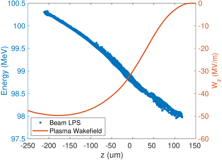
Our solution is based on the use of the self wakefields created by the beam in the plasma and can be employed both to remove the energy-chirp (acting like a dechirper) or tune it by adjusting the plasma density Wu et al. (2017); D’Arcy et al. (2019). The basic idea of the LPS manipulation is shown in Fig. 1, where we show the LPS and computed plasma wakefield (red line) produced by a 200 pC bunch in a plasma whose density is cm-3. By indicating the energy deviation of each particle along the bunch as , with the first order chirp term, the reported bunch has a negative chirp (higher energy particles on the tail) of MeV/m with an overall head-to-tail energy offset of MeV (). Once injected into the plasma, the electron bunch starts to create the wakefield. Strength of that field depends on plasma density and the density of the beam itself Fang et al. (2014). In our configuration the tail of the beam experiences a decelerating electric field and looses its energy while the head moves along an unperturbed plasma, keeping its energy actually constant. It is equivalent to a rotation of the beam LPS and, being induced by a wakefield approximately 50 MV/m, we expect that the energy-chirp can be completely removed by employing a few cm-long plasma structure.
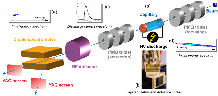
The experiment has been performed at the SPARC_LAB test-facility Ferrario et al. (2013); Pompili et al. (2018a) by employing 3 cm-long discharge-capillary filled by Hydrogen gas Pompili et al. (2018b); Marocchino et al. (2017); Pompili et al. (2017). The experimental setup is shown in Fig. 2. The bunch is produced by the SPARC photo-injector Alesini et al. (2003); Chiadroni et al. (2013b), consisting of a 1.6 cell RF-gun Cianchi et al. (2008) followed by two S-band accelerating sections embedded in solenoids coils Ferrario et al. (2010); Pompili et al. (2016a)) and one C-band structure. The plasma device consists of a plastic capillary with length cm and mm hole radius. The capillary is filled at 1 Hz rate with H2 gas (produced by an electrolytic generator) through two inlets placed at and and has two electrodes at its extremities connected to the discharge circuit with a 20 kV pulser Anania et al. (2016) and able to provide 230 A peak discharge-current with shot-to-shot fluctuation ns Pompili et al. (2018b). The peak plasma density reached in the capillary is cm-3, estimated by measuring the Hβ Balmer line with a Stark broadening-based diagnostics Filippi et al. (2016a). The capillary is installed in a vacuum chamber directly connected to a photo-injector by a windowless, three-stage differential pumping system, that ensures mbar pressure in the RF linac while flowing H2 into the capillary. This solution allows to avoid using any window, thus preventing the beam emittance deterioration by multiple scattering.
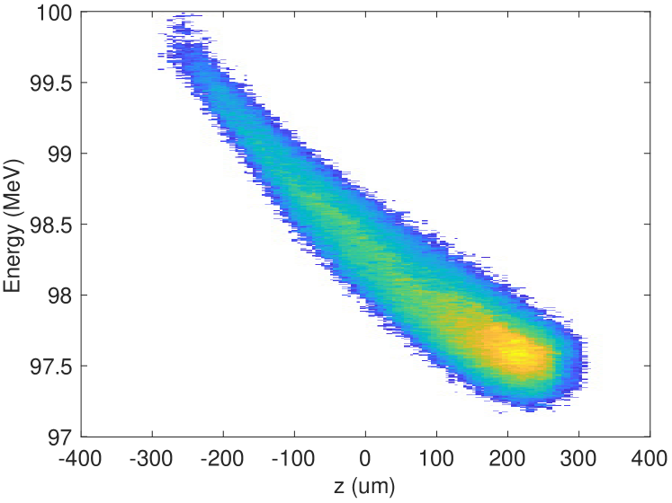
To experimentally produce a chirped LPS, like the one simulated in Fig. 1, we have used the first linac accelerating section as RF compressor by means of the velocity-bunching (VB) technique Serafini and Ferrario (2001); Ferrario et al. (2010), that allows to shorten the beam and imprint an energy-chirp on it Pompili et al. (2016b, a). The induced chirp is negative () till the maximum compression point (shortest bunch length) is reached. Figure 3 shows the measured LPS of the resulting beam. The electron bunch has 200 pC charge, 100 MeV energy (0.6 MeV energy spread) and 250 fs duration (corresponding to length), measured with a RF-Deflector device Alesini et al. (2006). Its normalized emittance on the horizontal (vertical) plane is . A triplet of permanent-magnet quadrupoles (PMQ) Pompili et al. (2018c) allows to squeeze the beam transverse size down to . All these quantities are quoted as rms. An almost linear negative chirp ( MeV/m) is achieved by moving the RF-phase of the compressor before the maximum compression point.
To measure the effect on the energy spectrum of the beam induced by the plasma, we transported the beam into the magnetic spectrometer downstream the capillary (with the RF-Deflector turned off) and made several measurements at different plasma densities. Once the is ionized it takes almost 10 to recombine Filippi et al. (2016b). During this time the plasma density is slowly decreases, thus by choosing the time-of arrival, by delaying the beam, we could choose the plasma density to interact with. Figure 4 shows the unperturbed energy spectrum, when there is no plasma in the capillary. In this case the overall energy spread is MeV, similarly to Fig. 3. When the plasma is turned on and its density tuned to cm-3 (corresponding to a delay of the order of s) we achieved the maximum reduction of the beam energy spread, down to MeV (see Fig.4).
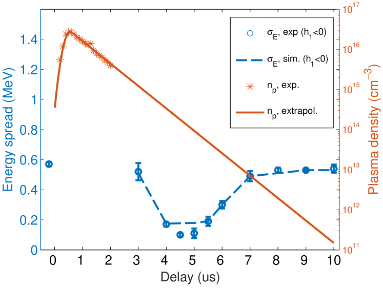
The evolution of the bunch energy spread for different plasma densities is shown in Fig. 5. Both quantities have been reported as a function of the delay of the discharge trigger. Being the Stark broadening diagnostics limited to the measurement of plasma densities above cm-3 (red stars), for lower values the expected density can be extrapolated (red line) only theoretically Johnson and Hinnov (1973). For the studied plasma densities the energy spread of the beam with initially negative chirp (see Figs.4) was decreasing, achieving its minimum at plasma density (blue circles). The missing points on the energy spread curve correspond to a time when the discharge occurs and active lens effects are taking place Pompili et al. (2018b).
The study on the manipulation of the LPS by the beam-driven plasma wakefields excited in a discharge-capillary structure is completed by analyzing the evolution of the negatively chirped beam configuration through the entire plasma channel. The interaction is described by using a 2D plasma wakefield code Lu et al. (2005) that also takes into account the finite plasma radial extension, being confined within the capillary radius Fang et al. (2014). Following our previous studies in which we completely characterized the longitudinal plasma density profile along the capillary, here the channel is numerically computed by assuming a flat profile in the central part with decreasing exponential tails extending 1 cm outside the capillary Filippi et al. (2016a); Biagioni et al. (2016); Filippi et al. (2018). The evolution of the bunch energy spread is shown in Fig. 5 as dashed blue line. As input beam we have used results of start-to-end simulations of the SPARC_LAB photo-injector by using the General Particle Tracer (GPT) code gpt , resulting in the LPS shown in Fig. 1. The excited plasma wakefields act along the entire channel to decelerate the particles in the tail of the beam, resulting in a final energy spread of the order of 0.1 MeV for the negatively chirped beam (blue circles), in agreement with the experimental measurements reported in Fig. 5.
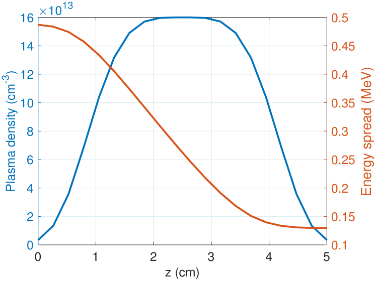
Figure 6 shows the evolution of the reduction of the bunch energy spread along the plasma channel. Here we are referring to the plasma density that provides the best energy spread reduction. As one can see, most of the reduction happens inside the capillary, where the plasma density is larger. On the contrary, on the input and exit ramps the reduction is almost negligible due to the extremely low associated plasma densities.
In conclusion, we have demonstrated the use of plasma wakefield to manipulate the longitudinal phase-space of an electron beam. For this purpose we have conducted a proof-of-principle experiments where we completely characterized a plasma-based device consisting of a 3 cm–long capillary filled by H2 gas. Our findings clearly proved that the large fields excited in a confined plasma can be used to tune the time-energy correlation of the particles according to the desired task. We have shown that such a device is not only compact but also can be highly flexible. For the beam with negative chirp we demonstrated a possibility to completely remove energy chirp and reduced the total energy spread from 0.6 to 0.1 MeV (the level of uncorrelated energy spread of the SPARC photo-injector).
Several applications can benefit of such results. It represents, for example, an interesting tool for FEL facilities to imprint an energy-chirp in the beam and achieve shorter bunch lengths in a magnetic compressor. The major advantage, however, is when employing this device downstream a plasma-based accelerator. It is well known that plasma-accelerated bunches have a large (negative) energy-chirp due to the larger fields experienced by the tail. In this case a second plasma module, as the one we have reported, might be implemented in order to remove such a correlation and reduce the overall energy spread. Due to high flexibility of the plasma dechirper, by manipulating the parameters of the system (like plasma density) and parameters of the beam (changing its density with focusing), we can easily tune the system to exactly remove the given correlated energy spread. It represents an essential feature in order to make the plasma-accelerated beams usable with conventional magnetic optics and in applications like Inverse Compton Scattering or FEL.
Acknowledgements.
This work has been partially supported by the EU Commission in the Seventh Framework Program, Grant Agreement 312453-EuCARD-2 and the European Union Horizon 2020 research and innovation program, Grant Agreement No. 653782 (EuPRAXIA). The work of one of us (A.Z.) was partially supported by BSF foundation.References
- Schoenlein et al. (1996) R. W. Schoenlein, W. Leemans, A. Chin, and P. Volfbeyn, Science 274, 236 (1996).
- Bacci et al. (2013) A. Bacci, D. Alesini, P. Antici, M. Bellaveglia, R. Boni, E. Chiadroni, A. Cianchi, C. Curatolo, G. Di Pirro, A. Esposito, et al., Journal of Applied Physics 113, 194508 (2013).
- Chiadroni et al. (2013a) E. Chiadroni, M. Bellaveglia, P. Calvani, M. Castellano, L. Catani, A. Cianchi, G. D. Pirro, M. Ferrario, G. Gatti, O. Limaj, S. Lupi, B. Marchetti, A. Mostacci, E. Pace, L. Palumbo, C. Ronsivalle, R. Pompili, and C. Vaccarezza, Review of Scientific Instruments 84, 022703 (2013a).
- Giorgianni et al. (2016) F. Giorgianni, E. Chiadroni, A. Rovere, M. Cestelli-Guidi, A. Perucchi, M. Bellaveglia, M. Castellano, D. Di Giovenale, G. Di Pirro, M. Ferrario, et al., Nature communications 7 (2016).
- Ackermann et al. (2007) W. Ackermann, G. Asova, V. Ayvazyan, A. Azima, J. Baboi, V. Balandin, B. Beutner, A. Brandt, A. Bolzmann, et al., Nature photonics 1, 336 (2007).
- Emma et al. (2010) P. Emma, R. Akre, J. Arthur, R. Bionta, C. Bostedt, J. Bozek, A. Brachmann, P. Bucksbaum, R. Coffee, F.-J. Decker, et al., nature photonics 4, 641 (2010).
- Allaria et al. (2012) E. Allaria, R. Appio, L. Badano, W. Barletta, S. Bassanese, S. Biedron, A. Borga, E. Busetto, D. Castronovo, P. Cinquegrana, et al., Nature Photonics 6, 699 (2012).
- Petrillo et al. (2013) V. Petrillo, M. Anania, M. Artioli, A. Bacci, M. Bellaveglia, E. Chiadroni, A. Cianchi, F. Ciocci, G. Dattoli, D. Di Giovenale, et al., Physical Review Letters 111, 114802 (2013).
- Tajima and Dawson (1979) T. Tajima and J. M. Dawson, Physical Review Letters 43, 267 (1979).
- Rosenzweig (1987) J. B. Rosenzweig, Physical Review Letters 58, 555 (1987).
- Rosenzweig et al. (1991) J. Rosenzweig, B. Breizman, T. Katsouleas, and J. Su, Physical Review A 44, R6189 (1991).
- Litos et al. (2014) M. Litos, E. Adli, W. An, C. Clarke, C. Clayton, S. Corde, J. Delahaye, R. England, A. Fisher, J. Frederico, et al., Nature 515, 92 (2014).
- Giannessi et al. (2011) L. Giannessi, A. Bacci, M. Bellaveglia, F. Briquez, M. Castellano, E. Chiadroni, A. Cianchi, F. Ciocci, M. Couprie, L. Cultrera, et al., Physical review letters 106, 144801 (2011).
- Blumenfeld et al. (2007) I. Blumenfeld, C. E. Clayton, F.-J. Decker, M. J. Hogan, C. Huang, R. Ischebeck, R. Iverson, C. Joshi, T. Katsouleas, N. Kirby, W. Lu, K. A. Marsh, W. B. Mori, P. Muggli, E. Oz, R. H. Siemann, D. Walz, and M. Zhou, Nature 445, 741 (2007).
- Leemans et al. (2006) W. Leemans, B. Nagler, A. Gonsalves, C. Tóth, K. Nakamura, C. Geddes, E. Esarey, C. Schroeder, and S. Hooker, Nature physics 2, 696 (2006).
- Faure et al. (2006) J. Faure, C. Rechatin, A. Norlin, A. Lifschitz, Y. Glinec, and V. Malka, Nature 444, 737 (2006).
- Piot et al. (2003) P. Piot, D. Douglas, and G. Krafft, Physical Review Special Topics-Accelerators and Beams 6, 030702 (2003).
- England et al. (2005) R. England, J. Rosenzweig, G. Andonian, P. Musumeci, G. Travish, and R. Yoder, Physical Review Special Topics-Accelerators and Beams 8, 012801 (2005).
- Antipov et al. (2014) S. Antipov, S. Baturin, C. Jing, M. Fedurin, A. Kanareykin, C. Swinson, P. Schoessow, W. Gai, and A. Zholents, Physical review letters 112, 114801 (2014).
- Bettoni et al. (2016) S. Bettoni, P. Craievich, A. Lutman, and M. Pedrozzi, Physical Review Accelerators and Beams 19, 021304 (2016).
- Penco et al. (2017) G. Penco, E. Allaria, I. Cudin, S. Di Mitri, D. Gauthier, S. Spampinati, M. Trovó, L. Giannessi, E. Roussel, S. Bettoni, et al., Physical review letters 119, 184802 (2017).
- Wu et al. (2017) Y. Wu, Y. Du, J. Zhang, Z. Zhou, Z. Cheng, S. Zhou, J. Hua, C. Pai, and W. Lu, Proc. IPAC2017 (2017).
- D’Arcy et al. (2019) R. D’Arcy, S. Wesch, A. Aschikhin, S. Bohlen, C. Behrens, M. Garland, L. Goldberg, P. Gonzalez, A. Knetsch, V. Libov, et al., Physical Review Letters 122, 034801 (2019).
- Fang et al. (2014) Y. Fang, J. Vieira, L. Amorim, W. Mori, and P. Muggli, Physics of Plasmas 21, 056703 (2014).
- Ferrario et al. (2013) M. Ferrario, D. Alesini, M. Anania, A. Bacci, M. Bellaveglia, O. Bogdanov, R. Boni, M. Castellano, E. Chiadroni, A. Cianchi, et al., Nuclear Instruments and Methods B 309, 183 (2013).
- Pompili et al. (2018a) R. Pompili, M. Anania, M. Bellaveglia, A. Biagioni, S. Bini, F. Bisesto, E. Chiadroni, A. Cianchi, G. Costa, D. D. Giovenale, M. Ferrario, F. Filippi, A. Gallo, A. Giribono, V. Lollo, A. Marocchino, V. Martinelli, A. Mostacci, G. D. Pirro, S. Romeo, J. Scifo, V. Shpakov, C. Vaccarezza, F. Villa, and A. Zigler, Nuclear Instruments and Methods in Physics Research Section A: Accelerators, Spectrometers, Detectors and Associated Equipment (2018a), https://doi.org/10.1016/j.nima.2018.01.071.
- Pompili et al. (2018b) R. Pompili, M. P. Anania, M. Bellaveglia, A. Biagioni, S. Bini, F. Bisesto, E. Brentegani, F. Cardelli, G. Castorina, E. Chiadroni, A. Cianchi, O. Coiro, G. Costa, M. Croia, D. Di Giovenale, M. Ferrario, F. Filippi, A. Giribono, V. Lollo, A. Marocchino, M. Marongiu, V. Martinelli, A. Mostacci, D. Pellegrini, L. Piersanti, G. Di Pirro, S. Romeo, A. R. Rossi, J. Scifo, V. Shpakov, A. Stella, C. Vaccarezza, F. Villa, and A. Zigler, Phys. Rev. Lett. 121, 174801 (2018b).
- Marocchino et al. (2017) A. Marocchino, M. P. Anania, M. Bellaveglia, A. Biagioni, S. Bini, F. Bisesto, E. Brentegani, E. Chiadroni, A. Cianchi, M. Croia, D. D. Giovenale, M. Ferrario, F. Filippi, A. Giribono, V. Lollo, M. Marongiu, A. Mostacci, G. D. Pirro, R. Pompili, S. Romeo, A. R. Rossi, J. Scifo, V. Shpakov, C. Vaccarezza, F. Villa, and A. Zigler, Applied Physics Letters 111, 184101 (2017).
- Pompili et al. (2017) R. Pompili, M. Anania, M. Bellaveglia, A. Biagioni, S. Bini, F. Bisesto, E. Brentegani, G. Castorina, E. Chiadroni, A. Cianchi, et al., Applied Physics Letters 110, 104101 (2017).
- Alesini et al. (2003) D. Alesini, S. Bertolucci, M. Biagini, C. Biscari, R. Boni, M. Boscolo, M. Castellano, A. Clozza, G. Di Pirro, A. Drago, et al., Nuclear Instruments and Methods A 507, 345 (2003).
- Chiadroni et al. (2013b) E. Chiadroni, A. Bacci, M. Bellaveglia, M. Boscolo, M. Castellano, L. Cultrera, G. Di Pirro, M. Ferrario, L. Ficcadenti, D. Filippetto, et al., Applied Physics Letters 102, 094101 (2013b).
- Cianchi et al. (2008) A. Cianchi, D. Alesini, A. Bacci, M. Bellaveglia, R. Boni, M. Boscolo, M. Castellano, L. Catani, E. Chiadroni, S. Cialdi, et al., Physical Review Special Topics-Accelerators and Beams 11, 032801 (2008).
- Ferrario et al. (2010) M. Ferrario, D. Alesini, A. Bacci, M. Bellaveglia, R. Boni, M. Boscolo, M. Castellano, E. Chiadroni, A. Cianchi, L. Cultrera, et al., Physical review letters 104, 054801 (2010).
- Pompili et al. (2016a) R. Pompili, M. Anania, M. Bellaveglia, A. Biagioni, F. Bisesto, E. Chiadroni, A. Cianchi, M. Croia, A. Curcio, D. Di Giovenale, et al., Nuclear Instruments and Methods in Physics Research Section A: Accelerators, Spectrometers, Detectors and Associated Equipment 829, 17 (2016a).
- Anania et al. (2016) M. Anania, A. Biagioni, E. Chiadroni, A. Cianchi, M. Croia, A. Curcio, D. Di Giovenale, G. Di Pirro, F. Filippi, A. Ghigo, et al., Nuclear Instruments and Methods in Physics Research Section A: Accelerators, Spectrometers, Detectors and Associated Equipment (2016).
- Filippi et al. (2016a) F. Filippi, M. Anania, A. Biagioni, E. Chiadroni, A. Cianchi, M. Ferrario, A. Mostacci, L. Palumbo, and A. Zigler, Journal of Instrumentation 11, C09015 (2016a).
- Serafini and Ferrario (2001) L. Serafini and M. Ferrario, in American Institute of Physics Conference Series, Vol. 581 (2001) pp. 87–106.
- Pompili et al. (2016b) R. Pompili, M. P. Anania, M. Bellaveglia, A. Biagioni, G. Castorina, E. Chiadroni, A. Cianchi, M. Croia, D. D. Giovenale, M. Ferrario, F. Filippi, A. Gallo, G. Gatti, F. Giorgianni, A. Giribono, W. Li, S. Lupi, A. Mostacci, M. Petrarca, L. Piersanti, G. D. Pirro, S. Romeo, J. Scifo, V. Shpakov, C. Vaccarezza, and F. Villa, New Journal of Physics 18, 083033 (2016b).
- Alesini et al. (2006) D. Alesini, G. Di Pirro, L. Ficcadenti, A. Mostacci, L. Palumbo, J. Rosenzweig, and C. Vaccarezza, Nuclear Instruments and Methods in Physics Research Section A: Accelerators, Spectrometers, Detectors and Associated Equipment 568, 488 (2006).
- Pompili et al. (2018c) R. Pompili, M. Anania, E. Chiadroni, A. Cianchi, M. Ferrario, V. Lollo, A. Notargiacomo, L. Picardi, C. Ronsivalle, J. Rosenzweig, et al., Review of Scientific Instruments 89, 033302 (2018c).
- Filippi et al. (2016b) F. Filippi, M. Anania, M. Bellaveglia, A. Biagioni, E. Chiadroni, A. Cianchi, D. Di Giovenale, G. Di Pirro, M. Ferrario, A. Mostacci, et al., Nuclear Instruments and Methods in Physics Research Section A: Accelerators, Spectrometers, Detectors and Associated Equipment (2016b).
- Johnson and Hinnov (1973) L. Johnson and E. Hinnov, Journal of Quantitative Spectroscopy and Radiative Transfer 13, 333 (1973).
- Lu et al. (2005) W. Lu, C. Huang, M. Zhou, W. Mori, and T. Katsouleas, Physics of Plasmas 12, 063101 (2005).
- Biagioni et al. (2016) A. Biagioni, M. Anania, M. Bellaveglia, E. Chiadroni, A. Cianchi, D. Di Giovenale, G. Di Pirro, M. Ferrario, F. Filippi, A. Mostacci, et al., Journal of Instrumentation 11, C08003 (2016).
- Filippi et al. (2018) F. Filippi, M. Anania, A. Biagioni, E. Brentegani, E. Chiadroni, A. Cianchi, A. Deng, M. Ferrario, R. Pompili, J. Rosenzweig, et al., Nuclear Instruments and Methods in Physics Research Section A: Accelerators, Spectrometers, Detectors and Associated Equipment (2018).
- (46) “Pulsar Physics,” http://www.pulsar.nl/gpt.