Optimization of Undulator Parameters for 125 GeV Drive Beam111Talk presented at the International Workshop on Future Linear Colliders (LCWS2018), Arlington, Texas, 22-26 October 2018.
Manuel Formela1222 manuel.formela@desy.de,
Gudrid Moortgat-Pick1,2, Sabine Riemann3, Andriy Ushakov1.
1 University of Hamburg, Luruper Chaussee 149, D-22761 Hamburg, Germany
2 Deutsches Elektronen-Synchrotron (DESY), Notkestraße 85, D-22607 Hamburg, Germany
3 Deutsches Elektronen-Synchrotron (DESY), Platanenallee 6, D-15738 Zeuthen, Germany
In the baseline design of the International Linear Collider (ILC) an undulator-based source is foreseen for the positron source in order to match the physics requirements. The baseline parameters are optimized for the ILC at GeV, that means an electron drive beam of GeV. Precision measurements in the Higgs sector, however, require measurements at GeV, i. e. running with the electron drive beam only at 125 GeV which imposes a challenge for achieving a high yield. Therefore the baseline undulator parameters have to be optimized as much as it is possible within their technical performances.
In this bachelor thesis we therefore present a theoretical study on the radiation spectra of a helical undulator, based on the equation for the radiated synchrotron energy spectral density per solid angle per electron in the relativistic, far field and point-like charge approximation. From this starting point the following undulator properties are examined: the deposited power in the undulator vessel, which can disrupt the functionality of the undulator‘s magnets, and the protective property of a mask on such disturbances and the number of positrons produced by the synchrotron radiation in a Ti-6Al-4V target. Those quantities were evaluated for various values for parameters as undulator period, undulator length and magnetic flux in order to find optimal baseline parameter sets for GeV.
1 Introduction
The International Linear Collider (ILC) as well as further future high-energy colliders as CLIC, for instance, have to provide polarized beams at high intensity as well as at high energy. Challenging is the production of the high-intense positron beam. The ILC uses an undulator-based positron source in the baseline design [1] that even produces a polarized positron beam. In this way, i.e. offering high intense and polarized electron and positron beams, the physics potential of the ILC is optimized and well prepared for high precision physics as well as new discoveries [2, 3]. Currently an initial energy of GeV is discussed [4], where the undulator scheme can be applied as well [5].
However, one should note, that the precision requirements can only be fulfilled if polarized positrons are available already at GeV! Otherwise the systematic uncertainties get too large, see [6, 7, 8, 9]. Applying simultaneously-polarized beams allows to be competitive to circular design-proposals that offer an order of magnitude higher luminosity but cannot provide polarized beams. Therefore it is of utmost importance to optimize the chosen baseline undulator-parameter set already for this first stage energy.
In the following we will have a look at different aspects on calculating the corresponding properties of helical undulators. First we discuss the analytical formulas of undulator radiation and the resulting produced positron number for a given undulator set-up. In section 2, we list the basic formulae used for describing undulator radiation, in section 3, we compare our undulator results with the values in the literature for the BCD- and RDR-design of the ILC. In section 4 we perform several undulator parameter scans in order to further optimize the baseline design –that was foreseen for GeV– for the currently discussed energy stage of GeV.
2 Undulator-based positron source scheme: fundamentals

The first formula in Fig. 1 shows the spectral energy density per solid angle of synchrotron radiation produced by one electron (in the far-field approximation, , for pointlike, , relativistic, , electrons) [10]. The given formula describes the synchrotron radiation with the photon frequency in general, valid for any trajectory of the electric charge.
The second equation in Fig. 1 expresses the spectral energy density applied for a specific charge trajectory, i. e. for a helical trajectory of the undulator electron. It contains the -th order Bessel function of the first kind and its first derivative . This equation holds for small radiation angles (), many undulator periods () and for reasonably small undulator parameter () [10].
By integrating the previous formula over all photon frequencies , one obtains the radiated energy per solid angle per electric charge ,
see Fig. 2. For the integration, the fraction with the squared sinus function in the numerator was approximated by the Dirac delta distribution (), which simplifies the integration.
Integrating over the whole solid angle leads to the radiated energy spectral density . Here the step function occurs.
Integrating numerically the radiated energy per solid angle over the solid angle, which covers the undulator vessel, results in the power deposited in the undulator vessel , when multiplied by the electron rate . Since this integral has no analytical solution, we solve it numerically.
Analogously, we get the produced positron number by dividing the radiated energy spectral density by the photon energy and by multiplying with the probability for electron positron pair production integrated over the photon frequency . The probability function is dependent on the cross section for electron positron pair production of a specific target material , the target density and its thickness .
3 Undulator scheme used in the RDR

The undulator set-up and the undulator parameters shown in Fig. 3 have been used for the ILC Baseline Conceptual Design (BCD) [11] and the Reference Design Report (RDR) [12], more details are given in [13]. This setup has been used to compare the detailed studies in [13] with our results, derived with the analytical formulae given in Figs.1 and 2, for the power deposited in the undulator vessel and for the produced positron number , where each set-up contains 20 half-cells, which in turn consist of 3 undulator modules, respectively. Each undulator module is made up of 2 undulator magnets of length separated by , see Fig. 3. The distance between neighbouring modules is and finally each half-cell starts and concludes with an empty segments of length. So the total length of a half-cell is , which adds up for all half-cells to the total undulator length of with a total magnetic length of .
3.1 Reproducing values for for the RDR set-up

In Fig. 4, we compare our results [14] for the deposited power in the undulator vessel in the BCD- and RDR-undulator set-ups for the ILC [11, 12] with the original studies presented in [13]: both graphs show logarithmic plots of the deposited power in the undulator vessel per meter versus the distance from the exit of the first long undulator magnet. In each of the two graphs there are four curves in red(BCD) and blue (RDR): dashed lines signify that only one long undulator magnet was considered, while solid lines represent calculations for the whole undulator set up.
The upper plot [14] and lower plot [13] show a good agreement of both results, not only graphically but also after more rigorous comparing. One important result from these plots confirms that the whole undulator radiation is expected to deposit a total power in the vessel of values above W/m for BCD and RDR parameters.
3.2 Implementing of undulator mask
Since the deposited power reaches, however, some tens W/m at the end of the undulator, a mask must be implemented. Otherwise powers of and above would disrupt the functionality of the magnetic coils and the vacuum. Such a limit was recommended by [15]. Fig. 5 shows the geometrical layout for the implementation of the mask.
The mask consists of some material reaching into the beam axis and therefore protecting the following vessel part from the synchrotron radiation. In this set-up, we have two undulator masks in each half-cell, located between the modules.
We calculated again the expected power deposited in the undulator vessel with the inclusion of the mask, see Fig. 6:

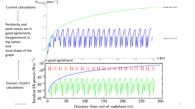
As in the case discussed before, the two graphics (upper [14] and lower [13] panel) in Fig. 6 are again in a good agreement and show the power deposited in the undulator versus the distance from the exit of the first long undulator piece. Each graph includes two sets of data points, both calculated for one single long undulator piece, but the blue set is based on the BCD parameters and the green one on the RDR parameters. The red vertical markers show the position of the mask. Obviously the mask prevents the vessel successfully from high power deposition.
After examining the effects of the mask on the deposited power for only one single -long undulator piece, one has also to calculate the effects of such a mass scheme for the whole undulator set-up.

In Fig. 7 the total power deposited in the vessel per meter is plotted versus the distance from the exit of the first -long undulator piece (upper panel [14], lower panel[13]). In the upper plot [14] (lower plot [13]), the blue (green) curve denotes the case when including the mask scheme. In both plots also the calculation of the deposited power without the mask has been added for comparison, i. e. the green line in the upper plot [14] and the blue line in the lower plot [13]. Both curves are made for the BCD parameters [11].
In both graphics, it can be seen that the mask limits the maximal power deposited per meter of vessel below one hundredth of W/m, and therefore succeeds in meeting the previously discussed limit for the deposited energy per meter of W/m.
Comparing both results for the case with the mask, show that there is a good agreement concerning the periodicity and peak values, but there are differences in dip values and the local shape of the graph. The cause for the disagreements might be due to different plot resolutions. Note, however, that the crucial important quantity is the peak value, which has to be below the upper limit condition. The peak value fulfills this condition and is similar in both independent calculations.
In Fig. 8 the same calculations were applied for the undulator including the mask scheme but for the RDR parameters [12]. The same conclusion as before can be drawn: the mask reduces successfully the deposited power below the agreed limit of W/m [15].
4 Steps towards optimizing the given undulator set-up for GeV
4.1 Calculation of for various parameter values for , , ,
After discussing the deposited power in detail, we study now the total number of produced positrons and try to maximize this quantity by altering the undulator parameter 0.9, 1.15, the undulator period 10.0, 11.5 mm, the undulator piece length , 2 m and the number of half-cells , 20, 22. We calculate the total number of positrons produced per electron plotted against the electron drive beam energy, see Fig. 9.

Please note, that the given number of positrons is the number, that would be produced only in the ideal case when all photons, which are emitted into the whole solid angle () would hit the target, so that the shown values in Fig. 9 can only be taken as an upper limit.
The number of lines shown in the graph is , where each curve was calculated under a unique combination of values of the undulator parameter , the undulator period , the undulator piece length and number of half-cells in the listed ranges.
The blue horizontal line at around positrons per electron denotes the result for the RDR parameters. This is regarded as our lower limit for the produced positron number and all curves below this line are dismissed in our study. Obviously, there are still large gain factors possible even within the small variations we made in the parameters set-ups.
In Fig. 10 we list all made parameter changes, ordered from highest to lowest number of resulting positrons. Those combinations that did not fulfill the threshold of RDR positron number are left out.

4.2 Test of the deposited power for parameter sets with highest
After deriving parameters sets that result in the highest positron number , this set up has to be checked again with regard to the corresponding deposited power in the undulator vessel .

It can be seen from Fig. 11 that the power limit of is not exceeded even for the parameter set resulting in the largest number of positrons within the listed variations of the parameters and at GeV.
4.3 Further improvements

The impact of several assumptions, listed in the following, that have been made will be studied and removed. For instance, we will drop systematically the made approximations, see item 1 in Fig.12, and study their impact on the derived positron number. Furthermore we include a fixed solid angle when integrating the number of positrons in order to cover only the target instead of the full angle. Still possible flaws in the undulator mask will be studied in order to resolve the small deviations between [13] and our current study [14].
Furthermore, we plan to perform the parameter scans on a more dense grid including engineering aspects and to extend the scanned parameters, for example, to include also the maximal mask heat load, in order to optimize the number of positrons for the given set-up in even more detail and more precisely. These studies are currently under work [16].
5 Conclusions
In this study we concentrated on finding optimized parameter sets for the given RDR undulator-scheme, originally designed for GeV, for an cms-energy of only 250 GeV. Since this energy step is physically of high interest for measuring the Higgs-boson couplings, mass and cross section, high luminosity is important already at this stage. The availability of polarized beams is substantial in this regard. In order to match the promised high-precision measurements, however, a polarized positron beam is mandatory as well, otherwise several systematic effects can not be controlled [7, 8, 9]. Therefore it is very important to optimize the foreseen undulator parameter set via moderate changes. As our study has shown, a rather large positron gain factor can be achieved even if only the magnetic field in the factor is slightly increased, the undulator period is slightly decreased and the number of cells is slightly enhanced. All the made changes do not result in exceeding the limit of deposited power in the vessel. Such promising results motivate the inclusion of further improvements concerning positron yield optimization for GeV and is currently under work.
Acknowledgements
This work was supported by the German Federal Ministry of Education and Research, Joint Research Project R&D Accelerator “Positron Sources”, Contract Number 05 H15GURBA.
References
- [1] C. Adolphsen et al., arXiv:1306.6328 [physics.acc-ph].
- [2] G. Moortgat-Pick et al., Eur. Phys. J. C 75 (2015) no.8, 371 doi:10.1140/epjc/s10052-015-3511-9 [arXiv:1504.01726 [hep-ph]].
- [3] J. A. Aguilar-Saavedra et al. [ECFA/DESY LC Physics Working Group], hep-ph/0106315.
- [4] K. Fujii et al., “The role of positron polarization for the inital GeV stage of the International Linear Collider,” arXiv:1801.02840 [hep-ph].
- [5] A. Ushakov, G. Moortgat-Pick and S. Riemann, arXiv:1801.08465 [physics.acc-ph].
- [6] S. Riemann, F. Dietrich, G. Moortgat-Pick, P. Sievers, A. Ushakov, Status of the undulator-based ILC positron source, these proceedings.
- [7] R. Karl, PhD Thesis ’From the Machine-Detector Interface to Electroweak Precision Measurements at the ILC’, University of Hamburg, February 2019.
- [8] R. Karl and J. List, arXiv:1703.00214 [hep-ex].
- [9] H. Aihara et al., ’The Internatonal Collider, A Global Project’, to appear soon.
- [10] B. M. Kincaid, J. Appl. Phys. 48 (1977) 2684. doi:10.1063/1.324138
- [11] Baseline Conceptual Design of the International Linear Colider, http://www.linearcollider.org/wiki/doku.php?id=bcd:bcd-home.
- [12] ILC Reference Design Report, http://www.linearcollider.org/ILC/Publications/Reference-Design-Report.
- [13] Scott, Duncan, ’An Investigation into the Design of the Helical Undulator for the International Linear Collider Positron Source’, PhD Thesis, University of Liverpool, February 2008.
- [14] M. Formela, ’Optimierung der Undulator-Strahlparameter für die Positronenquelle am ILC’, Bachelor Thesis, University of Hamburg, July 2018.
- [15] T. Bradshaw, private communication with Duncan J. Scott.
- [16] M. Formela, Master Thesis, University of Hamburg, 2019, in preparation.