IEEE Copyright Notice ©2019 IEEE. Personal use of this material is permitted. Permission from IEEE must be obtained for all other uses, in any current or future media, including reprinting/republishing this material for advertising or promotional purposes, creating new collective works, for resale or redistribution to servers or lists, or reuse of any copyrighted component of this work in other works.
Accepted to be Published in 2019, 41th Annual International Conference of the IEEE Engineering in Medicine and Biology Society (EMBC), Berlin Germany.
Analytic Model for Quadruped Locomotion Task-Space Planning*
Abstract
Despite the extensive presence of the legged locomotion in animals, it is extremely challenging to be reproduced with robots. Legged locomotion is an dynamic task which benefits from a planning that takes advantage of the gravitational pull on the system. However, the computational cost of such optimization rapidly increases with the complexity of kinematic structures, rendering impossible real-time deployment in unstructured environments. This paper proposes a simplified method that can generate desired centre of mass and feet trajectory for quadrupeds. The model describes a quadruped as two bipeds connected via their centres of mass, and it is based on the extension of an algebraic bipedal model that uses the topology of the gravitational attractor to describe bipedal locomotion strategies. The results show that the model generates trajectories that agrees with previous studies. The model will be deployed in the future as seed solution for whole-body trajectory optimization in the attempt to reduce the computational cost and obtain real-time planning of complex action in challenging environments.
I INTRODUCTION
The last decades have been characterised by a shift of paradigm in robotics from traditional industrial automation approaches towards a more human centric design that aims to improve both living and working conditions for humans. New robotic branches have formed to address issues regarding healthcare, haptics, human-robot interaction and collaboration have underlined the limited adaptability of traditional robotics, which was not conceived for dealing with interaction and uncertainties [1]. Therefore, scientists have started looking at animals as source of inspiration due to their dynamic dexterity in their daily living [3, 4, 2]. The study of how animals interact with environmental dynamics underlined the importance of having some degree of intrinsic softness in the mechanical structure, which lead to the development of soft-actuators (e.g., Variable Stiffness and Serial Elastic Actuators)[1]. Nevertheless, despite the introduction of these technologies have improved the performances of our robots in reacting to external perturbation, they are not comparable with animals’ abilities.
The identification of efficient and effective planning strategies in unstructured environments is critical to the development of mobile robotics platform that can enter daily living environments to improve human life quality and take over dangerous tasks [3, 1]. Quadruped robotics is among the viable solutions to replace humans operators in hazardous environments (e.g., deep mines, offshore oil rigs and disaster sites), offering both greater flexibility than wheeled robots and better stability characteristics compared to bipeds [1]. However, the high redundancy of the system kinematics implies a higher complexity in the planning stage, making the system less adaptable to sudden changes in the environment which trigger a replanning of the entire action. Yet again, we observe that animals are better than robots in reacting to perturbations, despite the limitations of their neural system in both transmission and elaboration of the information [3, 5, 6]. A possible answer to how nature could adapt to compensate for its intrinsic limitations may come to the latest studies in human motor control. Particularly interesting is the concept of dynamic primitives. They are collection of basic movements built through the interaction with external attractors, which can be combined to perform complex actions. This theory is an extension of the motor primitives that considered only the internal dynamics of the human body. The latter has also been integrated in a forward controller called the Passive Motion Paradigm (PMP) that can accurately reproduce reaching planar movements and wrist pointing task, where the external dynamics can be neglected [3, 2, 5].
Tommasino et al have recently formulated an extension to the passive motion paradigm, called , which extend the theory to include both the motor synergies and the interaction with an external environment [5]. Meanwhile, Tiseo et al have uncovered evidence that the model is also applicable to human locomotion strategies, which they have shown to be a dynamic reaching task on the gravitational attractor acting on the Centre of Mass (CoM) [3]. In particular, their results show that the spatio-temporal gait parameters (i.e., step length, step width, velocity and step frequency) are correlated by well defined relationship to achieve a stable behaviour that take advantage of the intrinsic dynamics of the biped. Thus, describing human locomotion as a dynamic reaching task that deploys the fixed points of the gravitational attractor to produce the close cycle behaviour that we observe in humans. The scope of this paper is to extend the model proposed in [3] to quadrupedal robots by modelling them as two synchronised bipeds with the two masses connected by a rigid rod as proposed in [7]. The aforementioned behaviour is also observed in humans when two individuals are carrying a ladder as reported in [8].
II Methods and Materials
The section presents with the extension of the bipedal model proposed by Tiseo et al in [3], and the validation method used to test the model for quadrupeds.
II-A Extension of the Bipedal Model
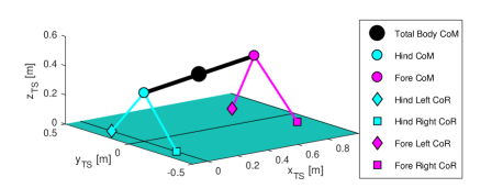
The gravitational attractor model of locomotion is based on a linear inverted pendulum model with variable length described in the task-space. It relies on the analysis on the intrinsic dynamics of the mechanical system to determine the relationships within the spatio-temporal parameters of the gait and the trajectories for the CoM and the foot swing. The extension to the quadruped is done considering two bipeds connected as shown in Fig. 1. The following formulation also considers that the feet do not move laterally; thus maintaining their lateral coordinates equal to half the step width ().
| (1) |
where i=F,H (Fore, Hind) indicates the fore or hind biped, j=R,L (Right, Left) refers to the foot. is the pendulum length, is the step length, is the walking velocity, and is the step frequency (i.e., cadence), is the maximum height of CoM, and is the starting phase. is the mediolateral amplitude of the CoM trajectory, and is the vertical amplitude of the CoM trajectory in which L describes the maximum extension achievable by the leg. and are the initial coordinates for the CoM and the Centre of Rotation (CoR), respectively. is the slope of the segment connecting the support foot CoR to the CoM and is the x-coordinate of the foot providing support. is the desired vertical clearance during swing, that has currently been set at 5 cm. The CoM trajectory of the quadruped is obtained from the bipeds’ CoM trajectories as follows:
| (2) |
II-B Gait Parameters
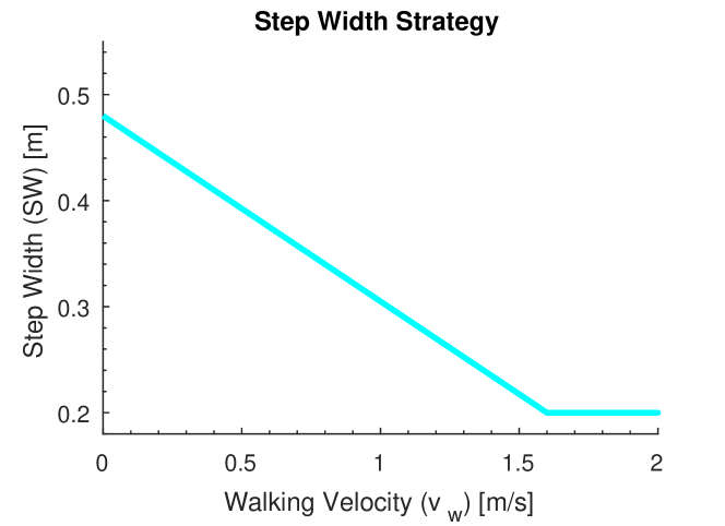
The model requires to define the gait parameters as function of the walking velocity to generate the CoM and CoR trajectories in equations (1) and (2). The Step Width (SW) has been defined based on constraints determined from previous experiment conducted with the ANYmal robot [1].
| (3) |
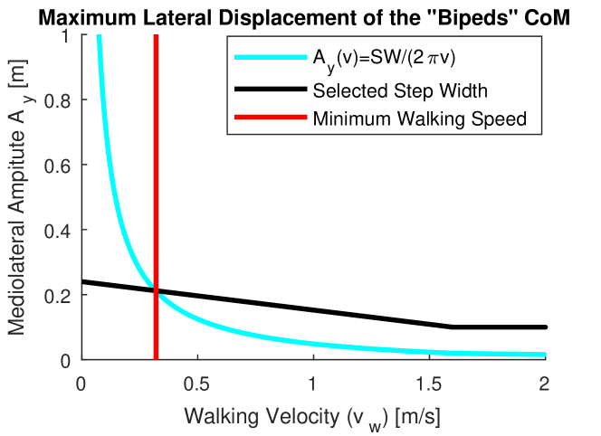
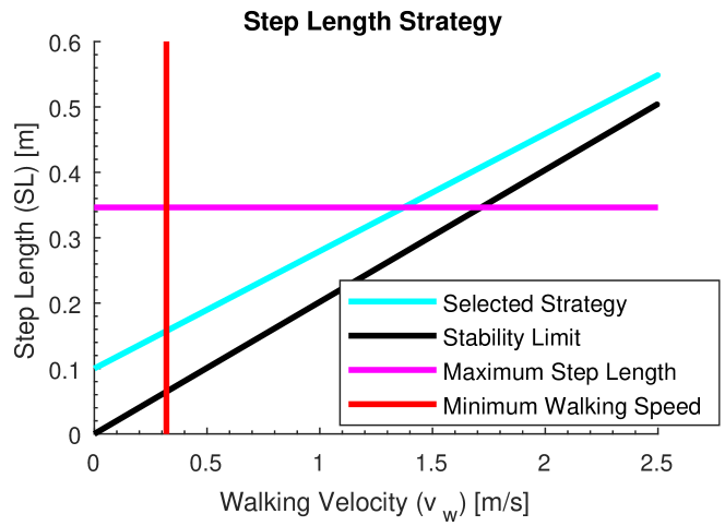
where is the mediolateral distance between the hip joints. The choice of the SW also introduces a limit of the minimum speed where the ballistic trajectory of the CoM is constrained within the two feet. Despite the impossibility to fully exploit the intrinsic inverted pendulum dynamics at lower speed, it is still possible to walk by constraining the CoM within the feet and actively track the ballistic trajectories during the foot transitions. Differently for the SW, the Step Length (SL) strategy accounts for the limitation imposed by the inverted pendulum dynamics, and it is defined as follows:
| (4) |
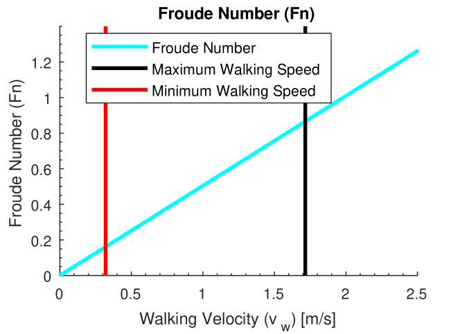
A Matlab (MathWoks, US) code was implemented for the simulations and only two inputs are and number of steps. The gait constraint identified by the model are compared with animal data to verify their consistency, and using the Froude Number (Fn=) to classify the gait strategies [9]. Sequentiality, the trajectories obtained with our model are compared with the results from previous research that analysed the coupling of two bipeds using either a rigid or a quasi-rigid interface [8, 7].
III Result
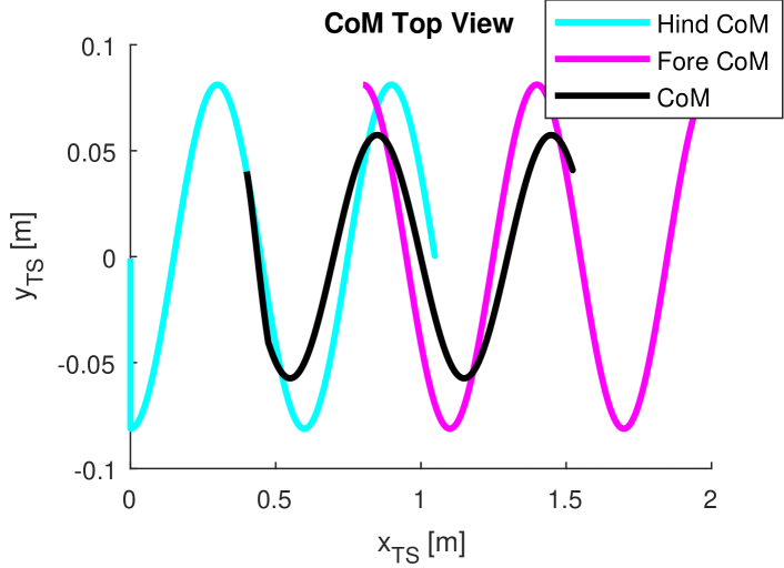
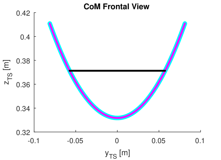
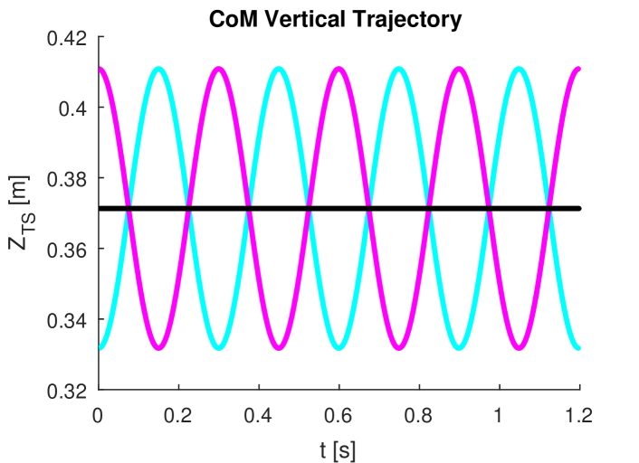
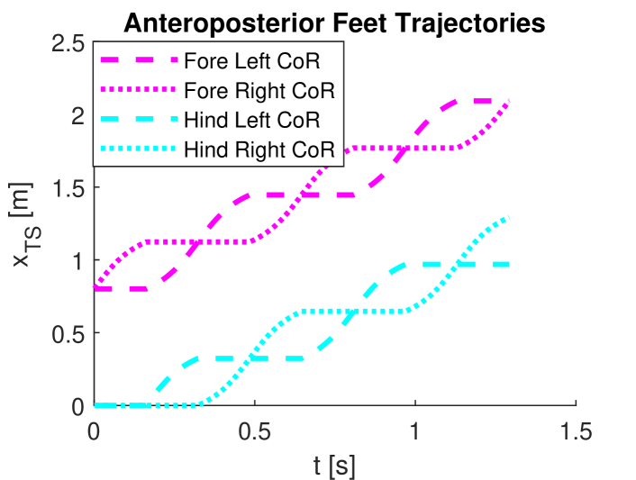
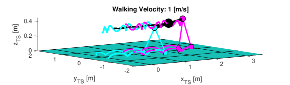
The range of walking speed admissible by our model is between 0.32 and 1.71 [m/s], which based on the Froude Number classification ranges from walking to trot. Specifically, it belongs to the walking range of dogs (Fn=[0.10,0.40), [9]) until a speed of 0.80 [m/s], before transitioning to the gait/canter range (Fn=[0.40, 4.00], [9], as reported in Fig. 2. The results show that the walking range is almost fully covered being the Froude Number at the minimum speed equal to 0.16; meanwhile, the maximum Fn achieved by the proposed model is 0.86. However, it shall be considered that animal trot includes a flight phase at higher speed, while our model imposes the absence of such phase. The trajectories generated by our model, shown in Fig. 3 for a walking speed of 1.00 [m/s], are consistent with both the results obtained by previous research both for quadruped and coupled humans.
IV Discussion
The data confirm that the model proposed by Tiseo et al., [3], can be extended to quadrupedal locomotion, and it can predict a range of admissible speed in dogs. These preliminary results show the theoretical feasibility of computationally efficient planner for quadrupedal based on the exploration of the gravitational dynamics. The proposed approach may also be used to reduce the computational cost of current methods by limiting their solution space to the set of solutions compatible with the saddle attractor locomotion theory. Furthermore, the model extension to quadrupeds shows interesting parallel with bipeds motor control, which may help to understand how the brain controls locomotion via the modulation of the Central Pattern Generators (CPG) located in the brain stem and spinal cord [6, 4].
In conclusion, the extension of the model to quadrupedal locomotion has been proved possible but, there is still work to be done before it can tested on real scenarios and perform essential locomotor behaviours (e.g., uneven terrain locomotion, turning, and obstacle avoidance). Nevertheless, we were able to gain some essential knowledge on how the body structure of a robot limits its locomotion abilities, that can be useful for the improvement of the hardware design.
References
- [1] G. Xin, H.-C. Lin, J. Smith, O. Cebe, and M. Mistry, ”A Model-based Hierarchical Controller for Legged Systems subject to External Disturbances,” IEEE/RSJ Int. Conf. Robot. Autom., pp. 4375-4382, 2018.
- [2] C. Tiseo, K. C. Veluvolu, and W. T. Ang, ”Evidence of a ’Clock’ Determining Human Locomotion,” in 2018 40th Annual International Conference of the IEEE Engineering in Medicine and Biology Society, EMBC 2018, 2018.
- [3] C. Tiseo, K. C. Veluvolu, and W. T. Ang, ”The bipedal saddle space: modelling and validation,” Bioinspir. Biomim., vol. 14, no. 1, p. 015001, Nov. 2018.
- [4] D. Bucher, G. Haspel, J. Golowasch, and F. Nadim, ”Central Pattern Generators,” in eLS, Chichester, UK: John Wiley & Sons, Ltd, 2015, pp. 1-12.
- [5] P. Tommasino and D. Campolo, ”Task-space separation principle: a force-field approach to motion planning for redundant manipulators,” Bioinspir. Biomim., vol. 12, no. 2, Feb. 2017.
- [6] K. Minassian, U. S. Hofstoetter, F. Dzeladini, P. A. Guertin, and A. Ijspeert, ”The Human Central Pattern Generator for Locomotion: Does It Exist and Contribute to Walking?,” Neuroscientist, vol. 23, no. 6, pp. 649-663, 2017.
- [7] T. M. Griffin, ”Biomechanics of quadrupedal walking: how do four-legged animals achieve inverted pendulum-like movements?,” J. Exp. Biol., vol. 207, no. 20, pp. 3545-3558, 2004.
- [8] J. Lanini, A. Duburcq, H. Razavi, C. G. Le Goff, and A. J. Ijspeert, ”Interactive locomotion: Investigation and modeling of physically-paired humans while walking,” PLoS One, vol. 12, no. 9, 2017.
- [9] A. S. Jayes and M. Alexander, R, ”Mechanics of locomotion of dogs and sheep,” J. Zool., vol. 185, pp. 289-308, 1978.