Time-Frequency Warped Waveforms
Abstract
The forthcoming communication systems are advancing towards improved flexibility in various aspects. Improved flexibility is crucial to cater diverse service requirements. This letter proposes a novel waveform design scheme that exploits axis warping to enable peaceful coexistence of different pulse shapes. A warping transform manipulates the lattice samples non-uniformly and provides flexibility to handle the time-frequency occupancy of a signal. The proposed approach enables the utilization of flexible pulse shapes in a quasi-orthogonal manner and increases the spectral efficiency. In addition, the rectangular resource block structure, which assists an efficient resource allocation, is preserved with the warped waveform design as well.
Index Terms:
Adaptive filters, interference suppression, pulse shaping, time-frequency warping, waveform design.I Introduction
The forthcoming wireless communication technologies are envisioned to support a vast variety of services. Recently, the International Telecommunications Union (ITU) has characterized the use cases for the fifth generation (5G) mobile networks as enhanced mobile broadband (eMBB), massive machine type communications (mMTC), and ultra-reliable low-latency communications (URLLC) featuring 20 Gb/s peak data rate, 106/km2 device density, and less than 1 ms latency respectively [1]. Therefore, a flexible design is needed to satisfy these challenging requirements and, the waveform, which is the essential component of an air interface, has to be designed precisely to accommodate such flexibility.
Orthogonal frequency-division multiplexing (OFDM) and its low peak-to-average-power ratio (PAPR) variant, discrete Fourier transform spread OFDM (DFT-s-OFDM) are the most favored waveforms that are being implemented in various standards. They provide several attractive attributes such as effective hardware implementation, low-complexity equalization, and straightforward multiple-input-multiple-output (MIMO) integration. In addition, the numerology concept (i.e., adaptive waveform parametrization) in the upcoming 5G standard [2] will improve the flexibility of these waveforms. On the other hand, OFDM and DFT-s-OFDM have severe high out-of-band emissions (OOBE) issue, which causes interference. Also, any disparity in waveform parametrization (such as subcarrier spacing) causes loss of orthogonality and leads to interference as well [3]. Commonly, the interference amount is managed by performing various windowing/filtering operations along with the guard allocation [4]. Numerous waveforms have been proposed to provide better time-frequency concentration while providing satisfactory spectral efficiency and sufficient flexibility [1, 5]. To fully exploit and further enhance the potential of the flexible air interface, it is necessary to increase the flexibility in waveform design.
This paper proposes a novel waveform design scheme that utilizes flexible pulse shapes and exploits axis warping transform [6, 7] to maintain the orthogonality. More specifically, the warping transform is non-uniform manipulation of the lattice samples and provides flexibility to handle the time-frequency occupancy of a signal. The utilization of flexible pulse shapes has been thoroughly investigated with certain trade-offs. For example, it is known that the edge subcarriers of an OFDM signal have a significant contribution to the OOBE. Therefore, raised cosine (RC) windows with higher sidelobe suppression capabilities are applied to edge subcarriers while lighter windows are applied to inner ones [8]. However, this approach shortens the cyclic prefix (CP) duration that is designated for the multipath channel and may cause inter-symbol-interference (ISI). In another study [9], RC filters of a filter bank multi-carrier (FBMC) signal are utilized with different roll-off factors to provide flexibility. Nonetheless, this technique does not retain the orthogonality of the pulses and leads to inter-carrier-interference (ICI). Despite the fact that the ISI and ICI problems in these studies can be mitigated with multi-user diversity, it is not always guaranteed. The proposed approach in this paper enables the utilization of flexible pulse shapes in a quasi-orthogonal manner and increases the spectral efficiency. In addition, the rectangular resource block structure, which assists an efficient resource allocation, is preserved with the warped waveform design as well.
II Axis Warping Transformation
A unitary operator is a linear transformation that maps a Hilbert space onto another one (i.e., ). Unitary operators preserves energy (i.e.,), and inner product (). Axis warping is a subclass of unitary transformations and can be expressed as follows [7]:
| (1) |
where is a smooth, one-to-one function that comprises a large subclass of unitary transformations. For example, a hyperbolic tangent function () or a sigmoid function () can serve as a warping operator. Also, the term represents the first derivative of the function . The relationship between the original and warped axis is formulated by the following equation:
| (2) |
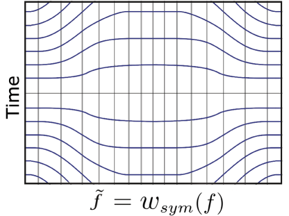
where represents the inverse function of , and stand for orthogonal axis such as time and frequency, and and are the warped axes. The warping transform enables non-uniform manipulation of axes and provides a flexible method to control the time-frequency occupancy of the signal. Fig. 1 presents two exemplary frequency-axis warping scenarios considering a symmetric and an asymmetric warping operators as follows:
| (3) |
| (4) |
where is an “S”-shaped monotonic function that have a range of , and and represent scaling parameters. Therefore, the given warping operators smoothly warp the frequency axis from to twice its scale . The choice of symmetricity depends on the application and will be detailed in the following sections.
III Frequency-Axis Warping Implementation
III-A Transceiver Design
The warped waveform concept is demonstrated with a multicarrier scheme that utilizes flexible pulse shaping filters. The pulse shapes that have lower sidelobes are assigned only to the edge subcarriers in order to decrease the OOBE in a spectrally efficient way. Afterward, axis warping is performed to maintain orthogonality between different pulse shapes and ensure that all subcarriers occupy the same time window. The baseband warped waveform with subcarriers can be expressed as follows:
| (5) |
where represents the inverse Fourier transform, stands for the complex data symbol, is the amplitude equalization factor, and is the pulse shaping filter. The RC pulse shapes with different roll-off factors () are utilized in this study. However, the choice of pulse shaping filter is not limited to RC, and any apodization function is suitable as long as Nyquist criteria are valid. Therefore, the design has two main variables to shape the signal, namely and . Also, there is a constraint on the design to preserve the rectangular resource block structure: all warped subcarriers should occupy the same duration . Nonetheless, the warping transform maps the complex Fourier-domain sinusoid to a chirp function . This mapping is realized as a chirp convolution with the RC window in the time domain. Due to the spectral nature of nonlinear chirps [10], the convolution results in time dispersion. Accordingly, the minimum allowed power ratio () of a subcarrier within the duration is set as a design criterion based on the performance requirements. The relationship between the subcarrier specific roll-off factor () and can be formulated considering constraint as follows:
| (6) |
The subcarriers are orthogonal to each other only if . However, can be slightly lower than the ideal case in practice, and they are considered to be quasi-orthogonal.
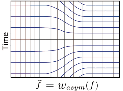
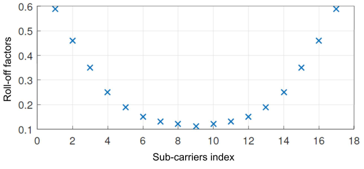
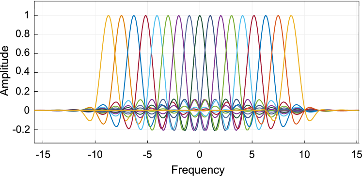
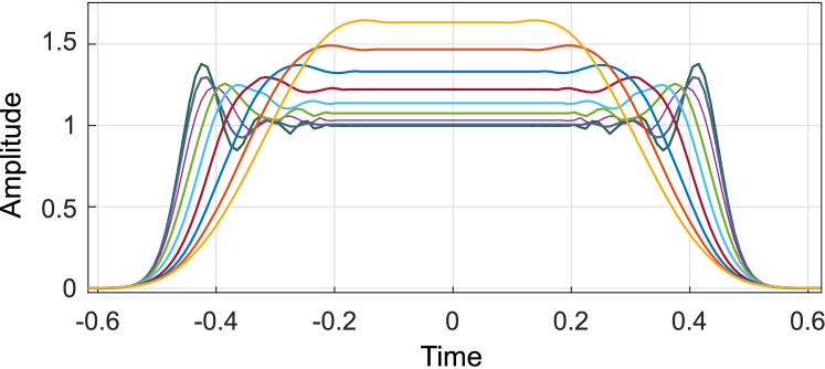
Fig. 2 presents the warped multicarrier concept with low number of subcarriers () for a better illustration. A symmetric warping operator is selected as . The subcarrier specific roll-off factors () are calculated using Eq. 6 considering for . As increases, the frequency domain localization of an RC pulse increases but it extends in the time domain. Though, warps the frequency axis and provides equal time domain occupation for RC pulses with different s. Since the chirp function is convolved with the RC windows in the time domain, dispersion occurs as shown in Fig. 2c. Also, please note that the subcarrier spacing increases on the edges as a result of non-uniform manipulation of , and compensates the amplitude decrease due to the factor in Eq. 1.
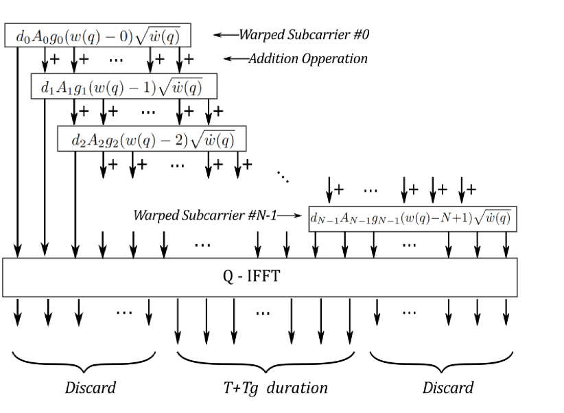
A block diagram of the proposed transceiver design is shown in Fig. 3, and the discrete form of Eq. 5 is expressed for better understanding as follows:
| (7) |
where and are the discrete time and frequency indices. represents the size of the FFT/IFFT operation and due to the warping expansion as mentioned earlier. Nonuniform fast Fourier transform (NUFFT) is required at the receiver to deal with the warped time-frequency lattice. A low complexity NUFFT implementation is proposed by coupling the FFT operation with an interpolation scheme that interpolates to the neighboring equispaced points [11]. However, this method is prone to the interpolation errors that cause ICI, and the following is proposed in our implementation:
-
1.
Using high order FFT/IFFT to have a better resolution in the frequency domain. is an integer multiple of and hence is upsampled.
-
2.
Designing the discrete (i.e., ) in such a way that the subcarrier positions meet one of the transform branches. Hence, should be an integer.
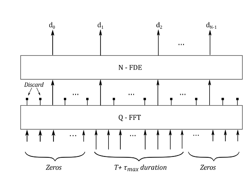
In the presence of a time dispersive channel, the signal reaches to the receiver with a spread over period , where is the maximum delay spread of the channel. The transmitter leaves a guard duration (), which is longer than to ensure the circularity of effective channel. At the receiver, the duration is padded with zeros, and a -size FFT is used to obtain the frequency domain representation. Afterward, the signal is downsampled properly, by discarding the oversampling introduced by the transmitter. A simple frequency domain equalizer (FDE) is performed to handle the multipath channel effect as similar to conventional OFDM systems.
III-B Performance Evaluation
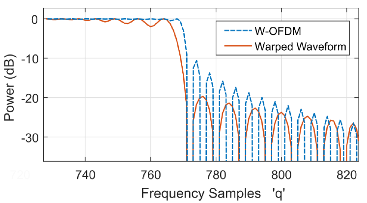
The performance of the warped waveform scheme is evaluated and compared with the conventional windowed-OFDM (W-OFDM) where all subcarriers are treated same for sidelobe suppression. The numerical evaluations are performed considering ( subcarriers are left empty due to the warping expansion) with an upsampling ratio of (hence ). A symmetric warping operator is used and the discrete warping function is designed in such a way that it has a decreasing slope profile over the edge subcarriers. More specifically, changes from to whereas subcarrier specific changes from to at the edges. The inner subcarriers have a fixed , since they don’t contribute to the OOBE significantly. To make a fair comparison, the warped waveform performance is compared with the performance of W-OFDM symbol that has ( subcarriers are left as guards) and (i.e., fixed for all subcarriers). Therefore, both symbols have the same spectral efficiency in terms of .
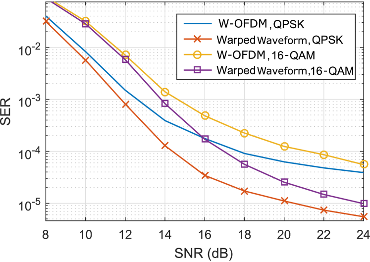
Fig. 4 shows that the OOBE of the warped waveform scheme is lower than the OOBE of W-OFDM. In other words, the warped waveform provides OOBE suppression in a more spectrally efficient way compared to W-OFDM that requires higher to achieve the same level. Also, the symbol error rate (SER) performance is evaluated in the presence of adjacent channel interference. The performance of the waveforms are compared for the same spectral efficiency with the assumptions of additive white Gaussian noise channel, same waveform utilization across adjacent channels, and a 10 power imbalance (i.e., power difference at the receiver). The results in Fig. 5 reveals that the proposed scheme performs better as expected due to lower interference from the adjacent channel.
The higher spectral efficiency with the proposed scheme is realized with increased computational complexity compared to conventional OFDM systems. FFT/IFFT blocks require multiplication operations for the warped waveform, whereas is required for OFDM. Also, there are additional multiplication operations for the pulse shaping, where represents the length of . Finally, the equalization consists of multiplication operations as similar to OFDM. Another drawback of the warped waveform design is increased PAPR. The increase is caused by expansion of the subcarriers and the PAPR increases as the number of warped edge subcarriers increases. However, our implementation shows that warping seven edge subcarriers is sufficient for an efficient sidelobe suppression and only 0.5 difference is measured at CCDF of (measured as 11.3 ). Therefore, the PAPR of the warped waveform can be considered as comparable with the PAPR of the conventional OFDM systems.
IV Conclusions
The proposed warped waveform concept improves the flexibility of waveform design and enhances the system performance with certain trade-offs. It provides better frequency localization which is critical for asynchronous transmission across adjacent sub-bands and harmony with other numerologies in the network. Also, it has the flexibility to manage each side of its spectrum differently by utilizing an asymmetric warping operator (e.g., Eq. 4). Hence, it prevents unnecessary OOBE suppression that decreases the spectral efficiency when requirements are different on each side of the band.
The results show the potential of such a flexible scheme and the design will be optimized for a future study. For example, this letter demonstrates the warped waveform concept with a multicarrier scheme. However, the concept is applicable to single carrier schemes as well.
The forthcoming communication systems are advancing towards improved flexibility in various aspects. Improved flexibility is crucial to cater diverse service requirements, and definitely, the pulse shape and time-frequency lattice should be a piece of the flexibility discussion as well. The warped waveform concept contributes to this futuristic goal and takes one step towards improved flexibility.
References
- [1] X. Zhang, L. Chen, J. Qiu, and J. Abdoli, “On the Waveform for 5G,” IEEE Commun. Mag., vol. 54, no. 11, pp. 74–80, Nov. 2016.
- [2] S. Parkvall, E. Dahlman, A. Furuskar, and M. Frenne, “NR: The New 5G Radio Access Technology,” IEEE Commun. Standards Mag., vol. 1, no. 4, pp. 24–30, Dec. 2017.
- [3] Z. E. Ankarali, B. Peköz, and H. Arslan, “Flexible radio access beyond 5G: A future projection on waveform, numerology, and frame design principles,” IEEE Access, vol. 5, pp. 18 295–18 309, 2017.
- [4] A. F. Demir and H. Arslan, “The impact of adaptive guards for 5G and beyond,” in 2017 IEEE 28th Annual International Symposium on Personal, Indoor, and Mobile Radio Communications (PIMRC), Oct 2017, pp. 1–5.
- [5] A. F. Demir, M. Elkourdi, M. Ibrahim, and H. Arslan, “Waveform design for 5G and beyond,” in 5G Networks: Fundamental Requirements, Enabling Technologies, and Operations Management. John Wiley & Sons, Ltd, 2018, ch. 2, pp. 51–76.
- [6] R. G. Baraniuk and D. L. Jones, “Shear madness: new orthonormal bases and frames using chirp functions,” IEEE Trans. Signal Process., vol. 41, no. 12, pp. 3543–3549, Dec. 1993.
- [7] ——, “Unitary equivalence: a new twist on signal processing,” IEEE Trans. Signal Process., vol. 43, no. 10, pp. 2269–2282, Oct. 1995.
- [8] A. Sahin and H. Arslan, “Edge Windowing for OFDM Based Systems,” IEEE Commun. Lett., vol. 15, no. 11, pp. 1208–1211, Nov. 2011.
- [9] Z. E. Ankaralı, A. Şahin, and H. Arslan, “Intentional-overlapping for multicarrier schemes based on user-specific filters,” Analog Integrated Circuits and Signal Processing, vol. 78, no. 3, pp. 683–690, Mar. 2014.
- [10] C. Cook, Radar Signals: An Introduction to Theory and Application. Academic Press, Feb. 2016.
- [11] J. A. Fessler and B. P. Sutton, “Nonuniform fast Fourier transforms using min-max interpolation,” IEEE Trans. Signal Process., vol. 51, no. 2, pp. 560–574, Feb. 2003.