Coherent coupling of single molecules to on-chip ring resonators
Abstract
We report on cryogenic coupling of organic molecules to ring microresonators obtained by looping sub-wavelength waveguides (nanoguides). We discuss fabrication and characterization of the chip-based nanophotonic elements which yield resonator finesse in the order of 20 when covered by molecular crystals. Our observed extinction dips from single molecules reach 22%, consistent with the expected Purcell enhancements up to 11 folds. Future efforts will aim at efficient coupling of a handful of molecules via their interaction with a ring microresonator mode, setting the ground for the realization of quantum optical cooperative effects.
1 Introduction
Controlled coupling of photons to a large network of optical emitters is not only a crucial step for quantum engineering platforms such as quantum simulation [1], but it also provides an avenue for studying fundamental collective phenomena in quantum mechanics [2]. A key requirement for achieving these goals is an efficient coupling of individual quantum emitters to a single photonic mode, which can be used as a “wire” for interconnecting them [3].
Theoretically, a photon can be reflected with unity probability from a dipolar two-level emitter if its spatial mode is matched to that of the emitter’s radiation pattern [4]. Indeed, substantial coupling efficiencies have been reported using various configurations such as near-field coupling [5], free-space focusing [6, 7] and coupling to subwavelength waveguides (nanoguides) [8, 9, 10, 11]. However, solid-state emitters confront a fundamental limitation in these endeavors because of their complex transition pathways and the influence of phonons. As a result, coherent emitter-photon interactions are hampered by a finite branching ratio defined as , where denotes the width of the zero-phonon-line (ZPL), and is the total linewidth. To remedy this issue, one can increase by coupling the ZPL to a single mode of an optical microcavity, thus, rendering the effect of unwanted transitions insignificant [12, 13, 14].
Very recently, we demonstrated near-unity coupling of single photons to the ZPL of an organic dye molecule placed in a high-finesse scannable Fabry-Perot microcavity [14]. Although the open structure of such a cavity ensures a high degree of control on the cavity resonance frequency and facilitates optimization of the molecule position, its design is not easily scalable to multiple emitters. An elegant alternative would be to employ a chip-based architecture consisting of a network of nanoguides and microresonators. This paper presents a realization of this goal by coupling single dibenzoterrylene (DBT) molecules embedded in a para-dichlorobenzene (pDCB) crystal to chip-based ring mircoresonators.
2 Coupling to nanoguide ring-resonators
It is known that the density of modes for the electromagnetic field is modified in the presence of boundaries, e.g., the mirrors of a Fabry-Perot cavity. This modification in turn affects the radiation properties of an emitter placed in it as compared to free space. The rate of emission into a single cavity mode () relative to that in free space () is given by the Purcell factor according to
| (1) |
where is the transition wavelength in vacuum, denotes the permittivity, is the quality factor, and signifies the cavity mode volume [15]. Thus, large enhancements can arise from high s and low s, i.e. if the mode is strongly confined in space and in frequency.
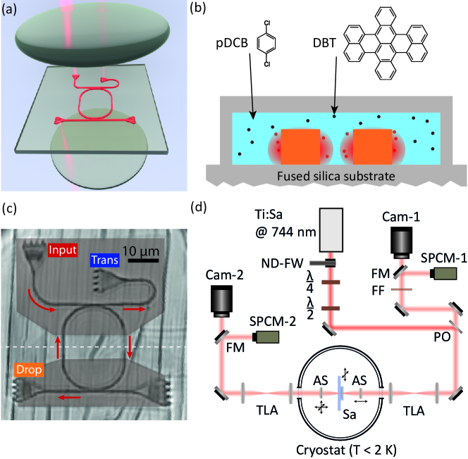
In our current work, we use a microscopic ring resonator composed of a looped nanoguide evanescently coupled to two other nanoguides, as illustrated in figure 1(a). In order to describe the coupling of a dipolar emitter to this structure, it is instructive to consider the emission into a linear nanoguide first. This can be calculated from the knowledge of the classical Green’s tensor, which accounts for the geometric and material properties of the nanoguide and its surrounding [3, 16, 17]. The Green’s tensor for propagation in a linear nanoguide can be decomposed into a transverse component () and a part along the nanoguide (), yielding , where . Here, denotes the effective longitudinal wave vector of the nanoguide mode. Following this approach, the rate of spontaneous emission into the mode of a nanoguide reads
| (2) |
where is the group velocity of light in the nanoguide and denotes the effective mode area of the nanoguide. We note that this treatment implicitly includes emission into the two opposite nanoguide directions.
If the radius of curvature of the ring is significantly larger than the emission wavelength, diffraction can be neglected and the resonator be locally treated as a linear nanoguide [18]. Hence, the transverse part of the Green’s tensor for a ring resonator remains the same as that of a linear nanoguide while the longitudinal component is modified according to , taking into account all clockwise (CW) and counter-clockwise (CCW) partial waves for a ring of circumference [18]. On resonance and for sufficiently large finesse (), the rate of emission for a dipole becomes
| (3) |
Here, we use the conventional definition , where FSR denotes the free spectral range of the resonator, and stands for the full width at half-maximum (FWHM) of its resonance spectrum. Therefore, the enhancement of emission into the ring resonator is summarized by the quantity since all other geometrical and material factors are included in . It can be readily shown that this formulation is equivalent to the familiar factor in Eq. (1) since the finesse, representing the number of times that a photon circulates in the resonator, incorporates the circumference of the resonating structure and the transverse area is accounted for in .
The factor of 2 in Eq. (3) signifies the contributions of the two degenerate modes CW and CCW of a ring resonator. It is well known that these two modes can be coupled by a nanoscopic scatterer [19], whereby a line splitting occurs if the rate of scattering into the resonator mode becomes comparable with its loss rate. In our work, the rate of the coupling between a molecule and the resonator mode amounts to a few hundred MHz, which is considerably lower than the resonator linewidth of several tens of GHz. Hence, the resonator spectrum is not split. Instead, we expect individual molecules to cause narrow dips on the broad resonator line.
The power of a light field traversing a nanoguide changes from to after encountering a single emitter [8], where the coupling of the latter to the nanoguide is characterized by , with signifying the rate of emission into free space. When the emitter is coupled to a ring resonator, the coupling parameter becomes
| (4) |
whereby both CW and CCW modes are accounted for [20, 21, 22]. It, thus, follows that Purcell enhancement (see Eq. (3)) improves , resulting in a stronger extinction effect by a single molecule. An important consequence of this enhancement is that it can compensate for intrinsically low coupling efficiencies caused by the molecular branching ratio or imperfect position and alignment of the emitter dipole moment. However, one should also bear in mind that because light scattered in the counter-propagating mode cannot interfere with the mode of the incident field in the drop or transmission ports, the dip and peak associated with the molecule are reduced at these ports. The new expression reads , yielding for the ideal case of . We note that because the molecular ZPL has a linear polarization, the presence of a longitudinal electric field [22] in our nanoguides does not affect our analysis.
3 Experimental methods
We use microresonators made of ring-shaped nanoguides coupled to straight nanoguides on a glass chip, which serve as input and output ports, see figure 1(a,c). The nanoguides are fabricated from a homogeneous layer using electron beam lithography and reactive ion etching [9]. A second substrate with a pre-structured indented channel of microscopic depth (1.4 ) is bonded from the top. This channel is filled with a molten DBT-doped pDCB via side openings (see figure 1(b) for a cross section of the structure). Upon a controlled decrease of temperature the liquid solidifies and forms a crystal around the nanoguides [9, 23]. The subwavelength dimensions of the nanoguides lead to strong evanescent tails, thus allowing molecules in the vicinity to interact with their modes.
The finesse of a ring resonator is determined by its round trip losses, which can stem from several mechanisms. First, one has to consider the leakage due to evanescent coupling with the straight nanoguides. Second, scattering caused by surface roughness of the microresonator leads to propagation losses. Third, the crystalline structure of the molecular host matrix can take on nanoscopic and microscopic irregularities upon formation and in the cooling process, also leading to scattering losses. Furthermore, bending losses might become significant for small resonator radii of curvature. Absorption in , however, is negligible for our wavelength and range of finesse.
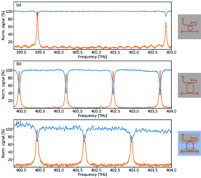
Figure 2(a) displays an example of spectra recorded at room temperature from a circular microresonator with radius of 5 m covered with poly methyl methacrylate (PMMA). Here, light from a tunable continuous-wave laser was coupled through the upper left grating (see figure 1(a,c)) and read either through the transmission port (upper right corner), or the drop port (lower left corner). The signal at the transmission (drop) port shows dips (peaks) signifying cavity resonances with GHz and THz, corresponding to .
As we shall see shortly, the finesse drops when the microresonator is covered with pDCB. In order to minimize the effect of crystal dislocations and cracks on the finesse, we employ a racetrack design and cover the curved parts by a polymer (mr-DWL micro resist technology GmbH, ) so that only the straight sections are exposed to pDCB, see figure 1(c). This minimizes the geometric mismatch of the crystalline axes with the resonator surface. In addition, the width of the nanoguide is widened from to in the protected area in order to reduce the evanescent field and, thereby, scattering losses. Figure 2(b) presents an example of room-temperature spectra recorded from a racetrack resonator fully covered with PMMA, displaying with GHz and THz. We attribute the lower finesse mainly to more scattering losses over the larger circumference of 82 m as compared to 31 m in figure 2(a).
Figure 2(c) shows the spectra from a racetrack resonator with identical design as that measured in figure 2(b), but now partially-protected with resist, covered with pDCB and measured at 2 K. We find that the resonator finesse is only slightly reduced to , which we attribute to residual small crystal defects. Unless stated otherwise, all low-temperature resonator data presented in this work were measured from this resonator. We note in passing that each fabricated chip contains a large number of resonator structures. Initial inspection of these allows one to select those with the best performance with regard to local crystal quality and molecule density.
The sample was optically accessed from both sides through two aspheric lenses with numerical aperture of 0.77, see figure 1(a,d). Light from a tunable Ti:Sapphire laser could be launched to and retrieved from these nanoguides via grating couplers. The outcoupled light was analyzed either by single-photon counting modules (SPCM-1/2, Excellitas Technologies SPCM-AQRM-14) or with cameras (Cam-1, Andor iXon 897; Cam-2, Hamamatsu ORCA-Flash 4.0). For fluorescence measurements bandpass filters (FF, Semrock ET785/60) were used.
4 Coherent coupling of molecules to a microresonator
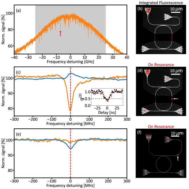
Having identified the resonances of our microresonator, we now take a closer look at the resonance at 402.94 THz of figure 2(c). As shown in figure 3(a), a frequency zoom into this resonance reveals narrow extinction dips caused by a large number of individual molecules coupled to the microresonator. The transitions of these chemically identical molecules undergo an inhomogeneous broadening caused by slight differences in their local environment. To ensure that each resonance can be attributed to a single molecule, in figure 3(c) we zoom further by about one hundred fold onto one of the resonances marked by an arrow. Here, we performed repeated frequency scans and aligned the resonances in individual scans before averaging to account for slight spectral diffusion in the order of one linewidth. We find that the coherent interaction of the resonator mode with a single molecule leads to an extinction dip of 22% in the drop port and a peak of 5% in the transmission port. The peak appears weaker because the transmission through the undercoupled resonator alone amounts to a 25% dip. Thus, the total effect of the molecule on the transmission channel follows . We note that the line shapes of the dip and the peak are not symmetric but resemble a Fano profile because the molecule was red-detuned from the cavity resonance by approximately ( of the FWHM). Using the relation established earlier, we arrive at .
The FWHM of about 34 MHz for the resonance depicted in figure 3(c) corresponds to the natural linewidth of DBT in pDCB and provides a strong evidence that the narrow resonances in figure 3(a) stem from single molecules. To verify this further, we performed Hanbury Brown and Twiss measurements on the red-shifted fluorescence from the emitter. The observed antibunching with displayed in the inset of figure 3(c) clearly testifies to the single-molecule origin of the signal (the deviation from zero is consistent with the measurement of the background).
The ability of our setup to image the interaction region on the chip (see cameras Cam-1,2 in figure 1(d)) allows us to locate individual molecules with respect to the resonator and nanoguide architecture. Here, we again exploit the red-shifted fluorescence emitted out of the chip plane. Figure 3(d) displays this for the incident light resonant with the ZPL of the single molecule studied in figure 3(c), confirming that the data originate from a well-defined location next to the microresonator. In figure 3(b), we show the cumulative fluorescence images recorded as the laser frequency was scanned over 50 GHz accounting for 82 molecular resonances. Again, the image nicely shows that the molecules causing the extinction dips are all in the close vicinity of the exposed part of the microresonator. To contrast these results, in figure 3(e,f) we also present an example of a molecule located along a linear nanoguide, i.e. not coupled to the resonator. As shown by the spectra in figure 3(e), a weak extinction dip of about 5% on the transmission port and no signal in the drop port report on the degree of coupling to a nanoguide without the cavity effect.
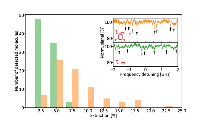
The degree of coupling for individual molecules varies due to the spread in their distances and orientations with respect to the microresonator. Therefore, we studied the statistical distribution of the size of extinction dips from 82 molecules within the grey band shown in figure 3(a). These data are presented by the orange histogram in figure 4, revealing extinction values reaching up to 22%. To asses the effect of the microresonator enhancement, we compared our findings with the outcome of measurements on 87 molecules along a linear nanoguide with an identical cross-section but without partial polymer coating. Since the microresonator was detuned from the inhomogeneous band of DBT in this case, the presence of the microresonator could be ignored. The green histogram in figure 4 summarizes the outcome of the measured extinction values for emitter-nanoguide coupling, reaching only about 7%. Again, if we use the relation we can extract for the coupling to a simple nanoguide, which is much smaller than the maximum measured value of mentioned above. Thus, we arrive at about seven-fold enhancement, which is in good agreement with the eight-fold theoretically predicted enhancement for (see Eq. (4)) if we consider corresponding to a Purcell factor of 11. A clear separation of the two histograms in figure 4 also provides a further strong evidence for the enhancement of the coherent coupling by our on-chip microresonators.
5 Outlook
We have reported a seven-fold increase in the coupling efficiency of single organic molecules to a chip-based microresonator as compared to a linear nanoguide. Higher coupling efficiencies of can be achieved if the current value of finesse were to be increased to while would require . This will demand improvements in the microresonator quality as well as its coupling to molecular samples. As presented in figure 2(a), our current fabrication process can deliver finesse in the order of 100, which we believe is limited by the etching quality of . In addition to improvements on this front, the quality of the molecular sample can be ameliorated by exploring different organic matrices and fabrication techniques, e.g. by using polymeric media [24, 25] or by placing individual nanocrystals [26] next to the microresonator.
We have demonstrated that a large number of molecules can couple to the same microcavity resonance. By integrating micro- and nano-electrodes on the chip architecture [27], we plan to tune the resonance frequencies of the individual molecules at will, thus, setting the ground for the generation of polaritonic light-matter states and many-body quantum optical interactions. As compared to other material systems (atoms, quantum dots, color centers), the large density of molecules provides a unique platform for reaching these goals.
We acknowledge the financial support by the Max Planck Society, an Alexander von Humboldt professorship and from the German Federal Ministry of Education and Research, co-funded by the European Commission (project RouTe), project number 13N14839 within the research program ”Photonik Forschung Deutschland”. D.R. and A.S. contributed equally to this work. We thank Pierre Türschmann and Nir Rotenberg for their contributions to the early stages of this work. We are also grateful to the MPL micro- and nanofabrication team (TDSU-1) for continuous support.
References
References
- [1] Noh C and Angelakis D G 2017 Rep. Prog. Phys. 80 016401
- [2] Chang D E, Douglas J S, González-Tudela A, Hung C L and Kimble H J 2018 Rev. Mod. Phys. 90(3) 031002
- [3] Haakh H R, Faez S and Sandoghdar V 2016 Phys. Rev. A 94(5) 053840
- [4] Zumofen G, Mojarad N M, Sandoghdar V and Agio M 2008 Phys. Rev. Lett. 101(18) 180404
- [5] Gerhardt I, Wrigge G, Agio M, Bushev P, Zumofen G and Sandoghdar V 2007 Opt. Lett. 32 1420–1422
- [6] Wrigge G, Gerhardt I, Hwang J, Zumofen G and Sandoghdar V 2007 Nat. Phys. 4 60
- [7] Maser A, Gmeiner B, Utikal T, Götzinger S and Sandoghdar V 2016 Nat. Photon. 10 450
- [8] Faez S, Türschmann P, Haakh H R, Götzinger S and Sandoghdar V 2014 Phys. Rev. Lett. 113(21) 213601
- [9] Türschmann P, Rotenberg N, Renger J, Harder I, Lohse O, Utikal T, Götzinger S and Sandoghdar V 2017 Nano Lett. 17 4941–4945
- [10] Javadi A, Ding D, Appel M H, Mahmoodian S, Löbl M C, Söllner I, Schott R, Papon C, Pregnolato T, Stobbe S, Midolo L, Schröder T, Wieck A D, Ludwig A, Warburton R J and Lodahl P 2018 Nat. Nanotechnol. 13 398–403 ISSN 1748-3395
- [11] Lombardi P, Ovvyan A P, Pazzagli S, Mazzamuto G, Kewes G, Neitzke O, Gruhler N, Benson O, Pernice W H P, Cataliotti F S and Toninelli C 2018 ACS Photonics 5 126–132
- [12] Arcari M, Söllner I, Javadi A, Lindskov Hansen S, Mahmoodian S, Liu J, Thyrrestrup H, Lee E H, Song J D, Stobbe S and Lodahl P 2014 Phys. Rev. Letters 113(9) 093603
- [13] Sipahigil A, Evans R E, Sukachev D D, Burek M J, Borregaard J, Bhaskar M K, Nguyen C T, Pacheco J L, Atikian H A, Meuwly C, Camacho R M, Jelezko F, Bielejec E, Park H, Lončar M and Lukin M D 2016 Science 354 847–850 ISSN 0036-8075
- [14] Wang D, Kelkar H, Martin-Cano D, Rattenbacher D, Shkarin A, Utikal T, Götzinger S and Sandoghdar V 2018 ArXiv e-prints
- [15] Walther H, Varcoe B T H, Englert B G and Becker T 2006 Rep. Prog. Phys. 69 1325
- [16] Gruner T and Welsch D G 1996 Phys. Rev. A 53(3) 1818–1829
- [17] Asenjo-Garcia A, Hood J D, Chang D E and Kimble H J 2017 Phys. Rev. A 95(3) 033818
- [18] Hümmer T, García-Vidal F J, Martín-Moreno L and Zueco D 2013 Phys. Rev. B 87(11) 115419
- [19] Mazzei A, Götzinger S, de S Menezes L, Zumofen G, Benson O and Sandoghdar V 2007 Phys. Rev. Lett. 99(17) 173603
- [20] Aoki T, Dayan B, Wilcut E, Bowen W P, Parkins A S, Kippenberg T J, Vahala K J and Kimble H J 2006 Nature 443 671
- [21] Srinivasan K and Painter O 2007 Nature 450 862
- [22] Junge C, O’Shea D, Volz J and Rauschenbeutel A 2013 Phys. Rev. Lett. 110(21) 213604
- [23] Gmeiner B, Maser A, Utikal T, Götzinger S and Sandoghdar V 2016 Phys. Chem. Chem. Phys. 18(29) 19588–19594
- [24] Donley E A, Bonsma S, Palm V, Burzomato V, Wild U P and Plakhotnik T 2000 Journal of Luminescence 87-89 109 – 114 ISSN 0022-2313
- [25] Walser A, Zumofen G, Renn A, Götzinger S and Sandoghdar V 2009 Mol. Phys. 107 1897–1909
- [26] Pazzagli S, Lombardi P, Martella D, Colautti M, Tiribilli B, Cataliotti F S and Toninelli C 2018 ACS Nano 12 4295–4303
- [27] Türschmann P, Rotenberg N, Renger J, Harder I, Lohse O, Utikal T, Götzinger S and Sandoghdar V 2017 arXiv:1702.05923v1