Laser wakefield driven generation of isolated CEP-tunable intense sub-cycle pulses
Abstract
Sources of intense, ultra-short electromagnetic pulses enable applications such as attosecond pulse generation, control of electron motion in solids and the observation of reaction dynamics at the electronic level. For such applications both high-intensity and carrier envelope phase (CEP) tunability are beneficial, yet hard to obtain with current methods. In this work we present a new scheme for generation of isolated CEP-tunable intense sub-cycle pulses with central frequencies that range from the midinfrared to the ultraviolet. It utilizes an intense laser pulse which drives a wake in a plasma, co-propagating with a long-wavelength seed pulse. The moving electron density spike of the wake amplifies the seed and forms a sub-cycle pulse. Controlling the CEP of the seed pulse, or the delay between driver and seed leads to CEP-tunability, while frequency tunability can be achieved by adjusting the laser and plasma parameters. Our 2D and 3D Particle-In-Cell simulations predict laser-to-sub-cycle-pulse conversion efficiencies up to 1%, resulting in relativistically intense sub-cycle pulses.
Electromagnetic pulses containing less than a single oscillation of the electromagnetic field are unique tools for the investigation and exploitation of non-adiabatic phenomena. One of the most prominent examples is the generation of attosecond pulses Krausz and Stockman (2014), the efficiency of which depends on the carrier envelope phase (CEP) of the driver pulse Corkum and Krausz (2007). Moreover, an intense driver is particularly advantageous since it can produce even shorter (e.g. zeptosecond Hernández-García et al. (2013)) pulses. Isolated sub-cycle pulses with both CEP-tunability and high energy are very attractive not only for attosecond pulse generation, but also many other applications in solid-state physics Günter et al. (2009); Hohenleutner et al. (2015) and nano-engineering Rybka et al. (2016). Therefore, developing methods to obtain isolated CEP-tunable high-intensity sub-cycle pulses is an active field of recent research. At present, solid-state lasers delivering relativistic intensity pulses are limited to durations above one and a half cycle Rivas et al. (2017), while scaling the intensity of sub-cycle pulses produced by parametric amplification methods remains challenging Manzoni et al. (2015), especially in the mid-IR Liang et al. (2017).
Plasma based methods, which are scalable even to relativistic intensities, offer hope to resolve this issue. In the context of attosecond pulse generation in the XUV regime, several techniques have been developed in order to produce isolated pulses, such as polarization Baeva et al. (2006); Tzallas et al. (2007); Yeung et al. (2015) or intensity gating Tsakiris et al. (2006); Heissler et al. (2012); Ma et al. (2015); Kormin et al. (2018) and exploitation of wavefront rotation Vincenti and Quéré (2012); Wheeler et al. (2012). More recently, plasma-based methods have been proposed to generate longer wavelength, e.g. mid-IR, single and sub-cycle pulses. We have shown that electron beams can be used to generate intense sub-cycle pulses, by amplifying a seed pulse reflected by a foil Thiele et al. (2019). Another technique to generate midinfrared, near-single-cycle pulses, which exploits the laser frequency down-conversion known to appear in laser-driven wakefields, has been proposed in Nie et al. (2018). However, all these plasma-based techniques are either not CEP-tunable or require a controllable CEP-stable high-intensity laser, which is technically challenging.
In this article, we demonstrate that isolated CEP-tunable intense sub-cycle pulses can be created by a frequency up-conversion process, which we refer to as laser-wakefield driven amplification (LWDA). We propose to inject a CEP-stable long-wavelength seed pulse of relatively low intensity in co-propagation with a high-intensity, not necessarily CEP-stable, driver laser pulse into a gas jet. The driver pulse ionizes the gas already at its rising edge and creates a plasma. Due to the ponderomotive force, the high-intensity laser pulse (driver) displaces the plasma electrons, creating a charge separation force which leads to plasma oscillations behind the laser pulse. These wakefield oscillations Gibbon (2005); Esarey et al. (2009) are strongly anharmonic for sufficiently intense drivers and form electron density spikes after each oscillation period. In the highly non-linear regime, the first period is completely void of electrons (forming the so-called bubble) and the first electron density spike is most pronounced. In the scheme proposed here, it is this electron density spike, moving close to the speed of light, which amplifies the seed pulse, leading to intense sub-cycle pulse generation.
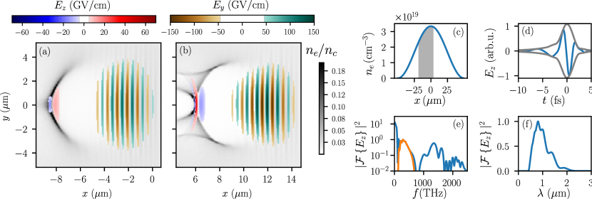
We demonstrate sub-cycle pulse generation by means of a 3D PIC simulation (see Fig. 1) using the code SMILEI Derouillat et al. (2018). A -polarized driving laser pulse and a -polarized seed pulse are injected along the direction. They are defined by their transverse electric field components and , respectively, according to
| (1) |
with amplitudes , beam waists , angular frequencies , phases , with variable seed CEP , driver CEP , and envelope of the form
| (2) |
The simulation parameters are summarized in Table 1. The gas-jet is modelled as a pre-ionized plasma with fixed ions and a cosine-squared electron density profile, see Fig. 1 with peak density cm-3, where is the critical density and and are the electron charge and mass respectively. The gas-jet has a short lengthscale with diameter (FWHM) , which is experimentally feasible Faure et al. (2018) (longer gas-jets can be used, as will be shown). The driver laser has relativistic strength, characterized by normalized peak vector potential (intensity ). Its duration that satisfies , where is the electron plasma wavelength and is the plasma frequency. This ensures that a wake with a pronounced density spike in the first period is excited Esarey et al. (2009). The seed pulse wavelength has been chosen to correspond to in order to ensure propagation of the seed, , while at the same time guaranteeing that the seed wavelength is longer than the electron skin depth, , which can be taken as an upper bound for the density spike characteristic length scale Thomas et al. (2016). The seed is sub-relativistic () while its energy is , which is well within reach of optical parametric amplification Woodbury et al. (2018).
| Fig. | (cm-3) | () | () | a0,L | (fs) | () | () | m) | ||||||||
|---|---|---|---|---|---|---|---|---|---|---|---|---|---|---|---|---|
| 1 | 50 | 5.8 | 2.5 | 4 | 0.3 mJ | 0.1 | 78 fs | 27 | 35 | 15 | 50 | 5 | ||||
| 2 | - | 5 | 2.5 | - | 4 | - | 0.005 | 64 fs | - | 105 | - | 120 | - | |||
| 3(a) | 23 | 5 | 2.5 | 4 | - | 0.005 | CW | 5 | 50 | 25 | 57 | 100 | ||||
| 4(b,d) | 152 | 25 | 2.5 | 20 | - | 0.005 | CW | 25 | 50 | 25 | 57 | 100 |
Fig. 1(a) shows how the first electron density spike of the wake behind the laser pulse amplifies the seed pulse and forms a sub-cycle pulse. The second and subsequent electron density spikes also create sub-cycle pulses. However, these have an intensity at least one order of magnitude smaller than that of the leading pulse, which is amplified by the dominant electron density spike, resulting in an isolated sub-cycle pulse. Amplification occurs predominantly over a distance of approximately in the rising edge of the gas-jet [grey-shaded area in Fig. 1(c)], where the high density gradient significantly enhances the leading density spike, while suppressing wavebreaking Mu et al. (2013). Amplification is interrupted shortly after the seed enters the declining part of the jet, due to wavebreaking associated with the plasma wavelength increase in the downramp Geddes et al. (2008), see Fig. 1(b). The peak electric field of the seed is amplified by a factor of 84 from to , while its peak wavelength is downshifted to [see Fig. 1(f)]. With respect to this wavelength the peak field of the sub-cycle pulse is relativistic, . The sub-cycle pulse is subsequently guided within the elongated plasma bubble until it exits the plasma, [1(d)] with an ultra-broad spectrum, intensity FWHM duration of fs or 0.75-cycles and polarization orthogonal to the driver. The latter property allows the sub-cycle and driver pulses to be separated after the interaction. Most of the spectral power of the sub-cycle pulse lies within octaves from 0.45 to 2 [1(f)]. The energy of the amplified seed has increased by a factor of almost 3, reaching 0.86 mJ, amounting to a pump to sub-cycle conversion efficiency of . Note that spectral components outside the regime of interest for this sub-cycle pulse have been filtered out, see Fig. 1(e) and the Supplemental Material sup .
In order to describe the amplification process in simpler terms, we develop a 1D model based on relativistic cold fluid theory. The propagation of the seed in the plasma can be described by the wave equation
| (3) |
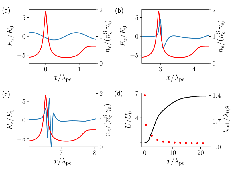
where , and are the wake scalar potential, electron fluid density and relativistic factor, respectively, is the seed vector potential and the background plasma density, in relativistic units sup . In the last step, use has been made of the fact that in the quasistatic approximation for the driver laser propagation Sprangle et al. (1990). The scalar potential for the nonlinear wake is determined by numerically solving V. et al. (1989); Sprangle et al. (1990); Esarey et al. (2009)
| (4) |
where is the vector potential of the driver laser, and is the driver group velocity Lu et al. (2007). The first period of the steady state, wakefield solution propagating at is shown in Fig. 2(a). The solution of Eq. (4) for is used in order to solve Eq. (3) numerically. As shown in Fig 2(d), the model predicts rapid seed wavelength decrease, as well as significant electromagnetic field energy gain. Fig. 2(b) shows that the wavelength downshift and energy gain is associated to localized amplification at the front of the density spike of the wake. This is consistent with the prediction of Ref. Thiele et al. (2019), that a pulse can gain energy from the declining part (with respect to ) of a sub-wavelength, moving density perturbation. This effect is distinct from the frequency upshift or “photon acceleration” Wilks et al. (1989); Esarey et al. (1990); Oliveira e Silva and Mendonça (1998); Murphy et al. (2006); Bu et al. (2015), associated with electromagnetic field propagation in a plasma with (spatially) decreasing density. In the latter case the pulse wavelength is shorter than the density variation length-scale and pulse energy increase is only possible through an associated pulse length increase Esarey et al. (1990). Nevertheless, also in our case plasma propagation effects are important and a purely beam-driven description Thiele et al. (2019) does not apply. Moreover, the amplification process is not due to a parametric process such as stimulated Raman scattering Kruer (2003), since the driver and seed polarization are orthogonal. Finally, note that LWDA is distinct from the formation of optical bullets in laser-wakefield acceleration, which occurs when a short wavelength probe is trapped inside the plasma density depression (bubble) created by the driver laser Sheng et al. (2000); Dong et al. (2010).
After propagation for , the rate of energy increase starts to decrease, since the local seed wavelength is not anymore longer than the density modulation length-scale. Moreover, the increased group velocity, due to the decrease in wavelength, of the amplified seed implies that the latter starts to dephase with respect to the density spike, see Fig. 2(c), leading to a gradual pulse lengthening. In the 3D PIC simulations of Fig. 1 wavebreaking occurs before dephasing becomes an issue and the sub-cycle pulse is guided within the bubble until the gas-jet exit, allowing the use of gas-jets of reasonable dimensions. We note that while the static wakefield model captures very well the salient features of sub-cycle pulse formation, amplification is higher in PIC simulations, due to the additional enhancement of the first density spike induced by the driver laser evolution in that case.
To discuss some additional features of the interaction we perform a parametric study with 2D simulations in a simplified setting in order to reduce computational costs, while still capturing the main effects (see sup for a comparison of 2D and 3D results). We consider a flat-top plasma density profile, the seed pulse is modeled within the continuous wave approximation (CW), in Eq. (1) and the remaining simulation parameters are summarized in Table 1. Fig. 3(a) shows the generated sub-cycle pulse at the exit of the plasma with half-cycle duration and peak wavelength of .
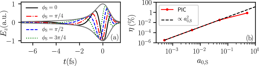
In order to tune the CEP of the sub-cycle pulse, it is sufficient to introduce a delay, , of the many-cycle seed pulse with respect to the laser pulse or to change the CEP of the seed . In the CW approximation studied here these two operations are equivalent, since ; the finite pulse duration case is studied in sup . Figure 3(a) presents the on-axis electric field shapes after the interaction using four different seed pulse delays in steps of (or phase-shifts of ). It can be seen that the sub-cycle pulse envelopes are the same, however the phases of the sub-cycle pulses are shifted by a value of . The synchronization level necessary to achieve a change of in CEP is . For the range of densities studied here, this corresponds to fs, which is within present experimental capabilities Golovin et al. (2018). Moreover, we show in sup that the sub-cycle phase is not sensitive to variations in the driver laser pulse duration or energy by up to 20%, making such control strategy viable.
According to the cold fluid model, Eq. 3, the interaction is linear in the seed transverse vector potential, implying a quadratic scaling of the energy conversion efficiency with the seed electric field amplitude. This is confirmed by our 2D PIC simulation results in Fig. 3(b),up to weakly relativistic seed pulse amplitudes. The sub-optimal scaling for is caused by the feedback of the seed pulse on the wake. In this case, the undepleted driver approximation, implicit in Eq. (4), does not hold; the wake loses a substantial fraction of its energy to the seed pulse and in Eq. (3) cannot be considered to be stationary and independent of the sub-cycle field anymore. Note that, as discussed in relation to Fig. 1, relativistic field strengths can nevertheless be reached using sub-relativistic seed pulses. Figure 3(b) shows that the laser-to-sub-cycle-pulse conversion efficiency reaches about 1%.
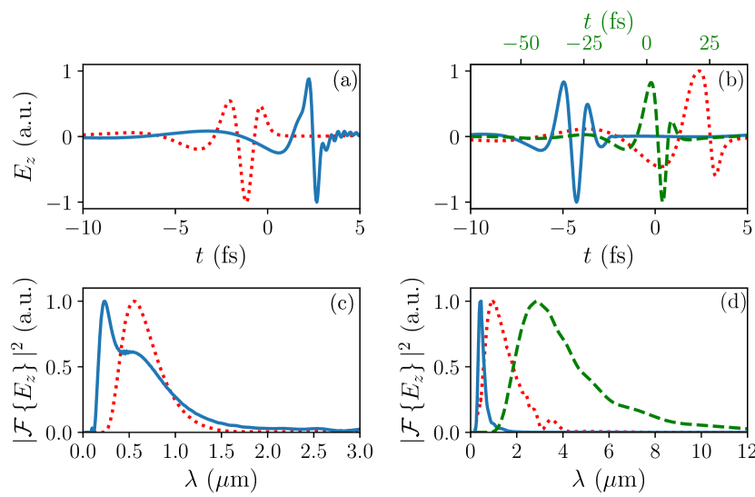
The 1D model suggests that, apart from the interaction length, the sub-cycle pulses’ spectra could be tuned with the driver-laser field strength and electron density . The larger and are, the narrower the amplifying electron density spikes, which naturally leads to shorter wavelength components in the sub-cycle pulse spectra, see Fig. 4. Tuning through the use of is limited by early wave-breaking of the amplifying electron density spike above (for this particular plasma density). Tuning through the variation of is, according to our simulations, effective as long as .
In order to scale our results to a wider range of densities, one can fix the driver laser wavelength to m and vary , while scaling all other parameters in proportion to the plasma wavelength. An example for low density plasma, , is shown as a green dashed line in Fig. 4(b,d), see Table 1. Due to the longer seed wavelength used in this case, , the generated sub-cycle pulse lies in the midinfrared.
In summary, we propose a scheme for the generation of isolated, CEP-tunable relativistic sub-cycle pulses by laser wakefield driven amplification of a seed electromagnetic pulse. The scheme has been shown to work over a wider range of plasma densities, utilizing seed pulses with wavelengths ranging from to to produce relativistic sub-cycle pulses with peak wavelengths adjustable from the midinfrared to the ultraviolet.
Acknowledgements.
The authors thank J. Ferri, M. Grech, L. Gremillet, G. Golovin, D. Guénot, V. Horný, M. Kaluza and L. Veisz for helpful suggestions, T. Blackburn for a careful reading of the manuscript and T. Fülöp for support. This work was supported by the Knut and Alice Wallenberg Foundation and by the Swedish Research Council, Grant No. 2016-05012. Numerical simulations were performed using computing resources at Grand Équipement National pour le Calcul Intensif (GENCI, Grants No. A0030506129 and No. A0040507594) and Chalmers Centre for Computational Science and Engineering (C3SE) provided by the Swedish National Infrastructure for Computing (SNIC, Grants 2017/1-484, 2017/1-393, 2018/3-297, 2018/2-13).References
- Krausz and Stockman (2014) F. Krausz and M. I. Stockman, Nat. Photonics 8, 205–213 (2014).
- Corkum and Krausz (2007) P. Corkum and F. Krausz, Nat. Physics 3, 381 (2007).
- Hernández-García et al. (2013) C. Hernández-García, J. A. Pérez-Hernández, T. Popmintchev, M. M. Murnane, H. C. Kapteyn, A. Jaron-Becker, A. Becker, and L. Plaja, Phys. Rev. Lett. 111, 033002 (2013).
- Günter et al. (2009) G. Günter, A. A. Anappara, J. Hees, A. Sell, G. Biasiol, L. Sorba, S. De Liberato, C. Ciuti, A. Tredicucci, A. Leitenstorfer, and R. Huber, Nature 459, 178 (2009).
- Hohenleutner et al. (2015) M. Hohenleutner, F. Langer, O. Schubert, M. Knorr, U. Huttner, S. W. Koch, M. Kira, and R. Huber, Nature 523, 572 (2015).
- Rybka et al. (2016) T. Rybka, M. Ludwig, M. F. Schmalz, V. Knittel, D. Brida, and A. Leitenstorfer, Nat. Photonics 10, 667–670 (2016).
- Rivas et al. (2017) D. E. Rivas, A. Borot, D. E. Cardenas, G. Marcus, X. Gu, D. Herrmann, J. Xu, J. Tan, D. Kormin, G. Ma, W. Dallari, G. D. Tsakiris, I. B. Földes, S.-w. Chou, M. Weidman, B. Bergues, T. Wittmann, H. Schröder, P. Tzallas, D. Charalambidis, O. Razskazovskaya, V. Pervak, F. Krausz, and L. Veisz, Scientific Reports 7, 5224 (2017).
- Manzoni et al. (2015) C. Manzoni, O. D. Mücke, G. Cirmi, S. Fang, J. Moses, S. Huang, K. Hong, G. Cerullo, and F. X. Kärtner, Laser & Photonics Reviews 9, 129 (2015).
- Liang et al. (2017) H. Liang, P. Krogen, Z. Wang, H. Park, T. Kroh, K. Zawilski, P. Schunemann, J. Moses, L. F. DiMauro, F. X. Kärtner, and K.-H. Hong, Nature Communications 8, 141 (2017).
- Baeva et al. (2006) T. Baeva, S. Gordienko, and A. Pukhov, Phys. Rev. E 74, 065401(R) (2006).
- Tzallas et al. (2007) P. Tzallas, E. Skantzakis, C. Kalpouzos, E. P. Benis, G. D. Tsakiris, and D. Charalambidis, Nat. Phys. 3, 846 (2007).
- Yeung et al. (2015) M. Yeung, J. Bierbach, E. Eckner, S. Rykovanov, S. Kuschel, A. Sävert, M. Förster, C. Rödel, G. Paulus, S. Cousens, M. Coughlan, B. Dromey, and M. Zepf, Phys. Rev. Lett. 115, 193903 (2015).
- Tsakiris et al. (2006) G. D. Tsakiris, K. Eidmann, J. Meyer-ter Vehn, and F. Krausz, New J. Phys. 8, 19 (2006).
- Heissler et al. (2012) P. Heissler, R. Hörlein, J. M. Mikhailova, L. Waldecker, P. Tzallas, A. Buck, K. Schmid, C. M. S. Sears, F. Krausz, L. Veisz, M. Zepf, and G. D. Tsakiris, Phys. Rev. Lett. 108, 235003 (2012).
- Ma et al. (2015) G. Ma, W. Dallari, A. Borot, F. Krausz, W. Yu, G. D. Tsakiris, and L. Veisz, Physics of Plasmas 22, 033105 (2015).
- Kormin et al. (2018) D. Kormin, A. Borot, G. Ma, W. Dallari, B. Bergues, M. Aladi, I. B. Földes, and L. Veisz, Nature Communications 9, 4992 (2018).
- Vincenti and Quéré (2012) H. Vincenti and F. Quéré, Phys. Rev. Lett. 108, 113904 (2012).
- Wheeler et al. (2012) J. A. Wheeler, A. Borot, S. Monchocé, H. Vincenti, A. Ricci, A. Malvache, R. Lopez-Martens, and F. Quéré, Nature Photonics 6, 829 (2012).
- Thiele et al. (2019) I. Thiele, E. Siminos, and T. Fülöp, Phys. Rev. Lett. 122, 104803 (2019).
- Nie et al. (2018) Z. Nie, C.-H. Pai, J. Hua, C. Zhang, Y. Wu, Y. Wan, F. Li, J. Zhang, Z. Cheng, Q. Su, S. Liu, Y. Ma, X. Ning, Y. He, W. Lu, H.-H. Chu, J. Wang, W. B. Mori, and C. Joshi, Nat. Photonics 12, 489 (2018).
- Gibbon (2005) P. Gibbon, Short Pulse Laser Interactions with Matter: An Introduction (Imperial College Press, London, 2005).
- Esarey et al. (2009) E. Esarey, C. B. Schroeder, and W. P. Leemans, Rev. Mod. Phys. 81, 1229 (2009).
- Derouillat et al. (2018) J. Derouillat, A. Beck, F. Pérez, T. Vinci, M. Chiaramello, A. Grassi, M. Flé, G. Bouchard, I. Plotnikov, N. Aunai, J. Dargent, C. Riconda, and M. Grech, Computer Physics Communications 222, 351 (2018).
- Faure et al. (2018) J. Faure, D. Gustas, D. Guénot, A. Vernier, F. Böhle, M. Ouillé, S. Haessler, R. Lopez-Martens, and A. Lifschitz, Plasma Phys. Control. Fusion 61, 014012 (2018).
- Thomas et al. (2016) J. Thomas, I. Y. Kostyukov, J. Pronold, A. Golovanov, and A. Pukhov, Physics of Plasmas 23, 053108 (2016), publisher: American Institute of Physics.
- Woodbury et al. (2018) D. Woodbury, L. Feder, V. Shumakova, C. Gollner, R. Schwartz, B. Miao, F. Salehi, A. Korolov, A. Pugžlys, A. Baltuška, and H. M. Milchberg, Opt. Lett. 43, 1131 (2018).
- Mu et al. (2013) J. Mu, F.-Y. Li, M. Zeng, M. Chen, Z.-M. Sheng, and J. Zhang, Appl. Phys. Lett. 103, 261114 (2013).
- Geddes et al. (2008) C. G. R. Geddes, K. Nakamura, G. R. Plateau, C. Toth, E. Cormier-Michel, E. Esarey, C. B. Schroeder, J. R. Cary, and W. P. Leemans, Phys. Rev. Lett. 100, 215004 (2008).
- (29) See Supplemental Material.
- Sprangle et al. (1990) P. Sprangle, E. Esarey, and A. Ting, Phys. Rev. A 41, 4463 (1990).
- V. et al. (1989) B. S. V., K. V. I., and S. A. S., JETP Lett. 50, 198 (1989).
- Lu et al. (2007) W. Lu, M. Tzoufras, C. Joshi, F. S. Tsung, W. B. Mori, J. Vieira, R. A. Fonseca, and L. O. Silva, Phys. Rev. ST Accel. Beams 10, 061301 (2007).
- Wilks et al. (1989) S. C. Wilks, J. M. Dawson, W. B. Mori, T. Katsouleas, and M. E. Jones, Phys. Rev. Lett. 62, 2600 (1989).
- Esarey et al. (1990) E. Esarey, A. Ting, and P. Sprangle, Phys. Rev. A 42, 3526 (1990).
- Oliveira e Silva and Mendonça (1998) L. Oliveira e Silva and J. T. Mendonça, Phys. Rev. E 57, 3423 (1998).
- Murphy et al. (2006) C. D. Murphy, R. Trines, J. Vieira, A. J. W. Reitsma, R. Bingham, J. L. Collier, E. J. Divall, P. S. Foster, C. J. Hooker, A. J. Langley, P. A. Norreys, R. A. Fonseca, F. Fiuza, L. O. Silva, J. T. Mendonça, W. B. Mori, J. G. Gallacher, R. Viskup, D. A. Jaroszynski, S. P. D. Mangles, A. G. R. Thomas, K. Krushelnick, and Z. Najmudin, Physics of Plasmas 13, 033108 (2006).
- Bu et al. (2015) Z. Bu, B. Shen, L. Yi, H. Zhang, S. Huang, and S. Li, Physics of Plasmas 22, 043102 (2015).
- Kruer (2003) W. Kruer, The Physics Of Laser Plasma Interactions (CRC Press, 2003).
- Sheng et al. (2000) Z.-M. Sheng, Y. Sentoku, K. Mima, and K. Nishihara, Phys. Rev. E 62, 7258 (2000), publisher: American Physical Society.
- Dong et al. (2010) P. Dong, S. A. Reed, S. A. Yi, S. Kalmykov, G. Shvets, M. C. Downer, N. H. Matlis, W. P. Leemans, C. McGuffey, S. S. Bulanov, V. Chvykov, G. Kalintchenko, K. Krushelnick, A. Maksimchuk, T. Matsuoka, A. G. R. Thomas, and V. Yanovsky, Phys. Rev. Lett. 104, 134801 (2010).
- Golovin et al. (2018) G. Golovin, W. Yan, J. Luo, C. Fruhling, D. Haden, B. Zhao, C. Liu, M. Chen, S. Chen, P. Zhang, S. Banerjee, and D. Umstadter, Phys. Rev. Lett. 121, 104801 (2018).