Controlling injection using a magnetic field to produce sub-femtosecond bunches in the laser wakefield accelerator
Abstract
It is shown that electron injection into a laser-driven plasma bubble can be manipulated by applying an external magnetic field in the presence of a plasma density gradient. The down-ramp of the density-tailored plasma locally reduces the plasma wave phase velocity, which triggers injection. The longitudinal magnetic field dynamically induces an expanding hole in the electron density distribution at the rear of the wake bubble, which reduces the peak electron velocity in its vicinity. Electron injection is suppressed when the electron velocity drops below the phase velocity, which depends on the size of the density hole. This enables the start and end of electron injection to be independently controlled, which allows generation of sub-femtosecond electron bunches with peak currents of a few kilo-Ampere, for an applied magnetic field of Tesla.
pacs:
52.38.Kd, 52.65.Rr1 Introduction
A plasma density wave or wake driven by the ponderomotive force of an ultraintense laser pulse can trap electrons and accelerate them to high energies [1, 2]. This well-known laser wakefield acceleration (LWFA) promises compact sources of high energy electrons because of the ultra-strong accelerating electric fields, which can exceed GV/m, in the so-called bubble regime that is characterized by a spherical electron cavity containing ions and surrounded by a high-density electron sheath [3, 4, 5]. In particular, the electron bunches obtained in the LWFA can be ultrashort, which is a major advantage of the LWFA and of great significance as drivers of ultrashort X-ray sources and potential compact X-ray free-electron lasers [6, 7, 8, 9, 10, 11, 12]. In general, the high-quality electron bunch should reside within the accelerating and focusing region of a wakefield with a length about in the linear regime [13, 14], where is the relativistic plasma wavelength. It is therefore expected that ultrashort electron bunches generated by a typical LWFA will have durations femtoseconds for plasma densities cm-3. There is considerable interest in generating even shorter electron bunches, with attosecond durations, for various applications including attosecond X-ray sources and direct imaging [15, 16, 17, 18].
In LWFA, a shorter bunch duration down to sub-femtosecond is possible if the injection of electrons into the wake is highly localized. The localized electron injection can be achieved by near-threshold self-injection [19, 20, 21], by colliding pulse injection [13, 14], or by up-ramp density transition [22]. Alternatively, the localized electron injection can be realized by manipulating the plasma wake structure. For instance, the local plasma wake phase and wavelength can be tuned by longitudinal plasma density tailoring [23]. To facilitate electron injection, the wake phase velocity can be reduced momentarily by a density down-ramp [24, 25, 26, 27, 28, 29]. In particular, the highly localized injection can be achieved if the time in which the peak forward-directed plasma electron velocity exceeds the wake phase velocity is ultrashort, which promises the generation of attosecond electron bunches [29]. So far, the generation of isolated sub-femtosecond electron bunches has not yet been demonstrated experimentally and several technical challenges still need to be overcome.
It is well known that the wakefield structure in the LWFA can be modified by a static external magnetic field. This may provide an alternative approach to control the electron injection [30, 31, 32, 33, 34]. By imposing an external transverse magnetic field that is on the order of hundreds of Tesla, the longitudinal trapping condition in the self-injection regime can be significantly relaxed [31], which also enhances the charge number of injected electrons. In contrast, it has been recently found that the external magnetic field required to modify the transverse trapping condition in the ionization-injection regime is only on the order of tens of Tesla [34], which promises efficient generation of high-quality electron bunches with both high charge and low energy spread. It is noted that strong magnetic fields of a few tens of Tesla can be generated in a small volume by either traditional technology in laboratories [35, 36] or a novel proposal using twisted laser beams [37].
In this paper, we present a study of the manipulation of the laser-driven plasma bubble to control the persistence of electron injection, through combining a density-profile-tailored plasma with a longitudinal magnetic field. We show that the static longitudinal magnetic field modifies the transverse structure of the bubble, while the density gradient changes its longitudinal structure. The magnetic field induces a radial density hole in the bubble rear [32, 33], which expands and as the bubble evolves along the density down-ramp. Electron injection is triggered by the decreasing phase velocity of the bubble along the density down-ramp, and then suppressed by the expanding hole at the bubble rear. In this way, the position and persistence of electron injection can be controlled, leading to injection of isolated sub-femtosecond electron bunches.
2 Theoretical analysis
We first consider the effect of the plasma density gradient on the laser-driven plasma wake. In a tenuous inhomogeneous plasma, the wake wave has a local phase , where is the relative coordinate, and are the local plasma frequency and wavenumber, respectively. For a non-relativistic laser pulse, the wavelength only depends on the local plasma density , and therefore , where and are the normalized wake phase and laser group velocities, respectively. For a relativistic laser pulse with initial peak normalized potential amplitude , the effect of laser amplitude evolution on and must be considered appropriately. In this case, the ponderomotively expelled electrons oscillate transversely at the relativistic betatron frequency with the Lorentz factor in the ponderomotive approximation [38]. The initially stationary electrons return to the laser axis after half a betatron oscillation period and cross at the bubble rear. The velocity of the bubble rear, or the phase velocity at , where the longitudinal electric field , can be formulated as [29], where . This approximately gives the bubble velocity as
| (1) |
where is the plasma density normalized to the plateau density , and is the plasma wavelength corresponding to . The effects of the plasma density gradient and laser amplitude evolution are included in the terms and , respectively. The bubble velocity can be reduced by decreasing the plasma density and/or increasing the laser amplitude.
Under a strong longitudinal magnetic field , however, the bubble rear will open up [32, 33]. In this case, the electrons moving along the bubble sheath experience a time-varying magnetic field , where is the radius of the bubble. This induces an azimuthal electric field, which causes the sheath electrons to obtain an azimuthal velocity and rotate reversely around the laser axis. As a consequence, a huge longitudinal magnetic field is self-generated and distributes locally inside the density-hole region, with the same direction as , as described by Lenz’s law [33]. Finally, the radial motion of sheath electrons is governed by
| (2) |
where is the centrifugal force, and is the radial wakefield [4, 5]. It is this centrifugal force that opens up the bubble rear, because it tends to infinity when . Considering the equations for the transverse momentum only, the radius of the hole in the opened bubble rear should be governed mainly by the plasma density and magnetic field, which can be approximated by [32], where is the electron cyclotron frequency. Nevertheless, since electrons experience a strong longitudinal acceleration in the wakefield, the hole radius also depends on the instantaneous mean electron energy around the bubble rear, because the centrifugal force .
3 PIC simulations
To demonstrate the combined effects of plasma density tailoring and the longitudinal magnetic field on the wake structure, and therefore the consequent electron injection, three-dimensional (3D) particle-in-cell (PIC) simulations using OSIRIS [39] have been performed. In each simulation, a m3 simulation box moves along the z-axis at the speed of light. It is subdivided into cells with particles per cell. The plasma comprises a plateau background density corresponding to a plasma frequency and a Gaussian density bump
| (3) |
where is the relative amplitude of the density peak at , is the characteristic length of the Gaussian bump. Such a plasma density profile is realizable in experiments as longs as the ramp does not need to be too steep [26, 40]. A linearly polarized (along y-direction) laser pulse with duration of 30 fs, with an initial peak normalized amplitude and a waist of 15 m at focal plane , is used. The laser wavelength is 0.8 m, correspondingly the critical plasma density cm-3. A uniform external magnetic field is assumed to be along the -axis and is exerted on the whole plasma region.
3.1 Evolution of phase velocity due to bubble stretch
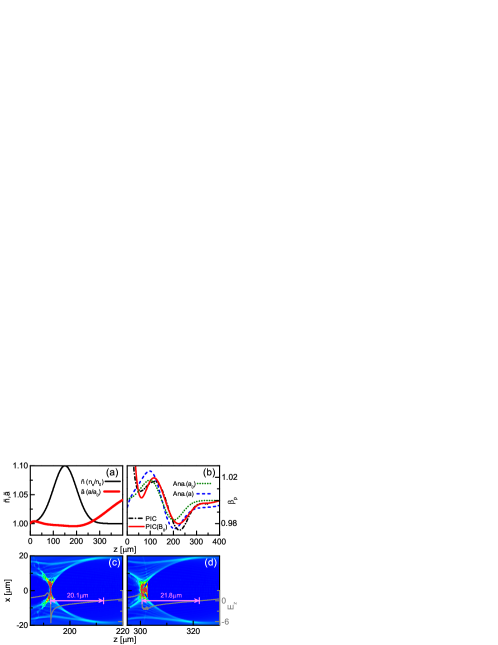
Figure 1(a) displays the local plasma density and the laser amplitude as functions of the propagation distance . It is seen that the laser amplitude decreases slightly along almost the whole density bump region before z=200 m and then increases rapidly because of self-focusing. Substituting into Eq. (1), the local wake phase velocity can be calculated analytically. Figure 1(b) illustrates that the bubble rear velocity decreases dramatically due to the decreasing plasma density at the down-ramp around m, and the simulation result is in good agreement with the analytical result with evolving laser amplitude , which is compared with the one with constant . The reduction in the bubble velocity is attributed to the increase of the wavelength of the wake. The longitudinal stretch of the wake bubble is confirmed in figures 1(c) and 1(d), where the radius of the bubble increases from to m. As a consequence, electron injection is triggered, as is illustrated in figure 1(d). From figure 1(b), one notes that the reduction in the bubble velocity is slightly weakened by a longitudinal magnetic field T. This is because the continuously injected electron charge in the case slightly pushes back the bubble rear, due to the strong Coulomb repulsion, and hence reduces the bubble velocity further, while suppressing electron injection for non-zero , as will be discussed below. Because both the laser evolution and the injected charge can reduce the phase velocity, we observe that it is hard to finely control the density-gradient profile to produce stable sub-femtosecond electron bunches.
3.2 Magnetic field induced injection suppression along a density down-ramp
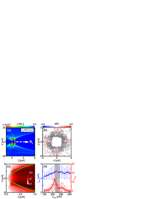
To understand the effect of a non-zero on the electron injection, it is important to reveal first its effect on the bubble structure. As previously predicted [32, 33], figure 2(a) confirms the appearance of an open bubble rear for T. More importantly, the electron injection in this case is found to take place over a short distance. The electron bunch ( m) resulting from this highly localized injection is much shorter than that ( m) in the case with . The transverse distribution of the electrons around the open bubble rear is displayed in figure 2(b), where the suppression of electron injection is confirmed because only a small number of electrons around the bubble rear can simultaneously achieve the local bubble velocity and be focused with . Because of the open bubble rear, the wake accelerating field has its maximum amplitude away from the laser axis, as shown in figure 2 (c). As a consequence, the most efficient acceleration region for the electrons moving along the bubble sheath is located at a distance away from the axis. Defining , and as the RMS Lorentz factor, radius and longitudinal position of energetic electrons () around the bubble rear, figure 2(d) shows that both and increase before the occurrence of electron injection. The increase of can be attributed to the prolonged acceleration time in the expanding bubble along the density down-ramp. With increasing , however, also increases because the centrifugal force . As a result, finally, the increase of inhibits electron injection.
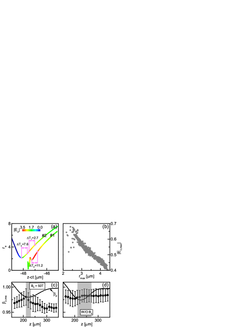
To explain the suppression of electron injection through increasing , the instantaneous accelerating fields along the trajectories of two typical electrons are compared in figure 3(a). Firstly, we find that the injected electron that is closer to the axis experiences a stronger accelerating field than the non-injected electron . Defining and as the maximum of and the corresponding radial position where this maximum is achieved, figure 3(b) shows a linear negative correlation between and . Secondly, we find that the most efficient acceleration region for electron is much closer to its turning point than that for electron . Therefore, electron can stay in the efficient acceleration region for a longer period of time than electron . The stronger accelerating field and longer accelerating time combine to guarantee that electron can be accelerated to the bubble velocity and therefore be trapped. In contrast, electron can not be injected since it is further away from the axis. With increasing , more and more energetic electrons will be far away from the axis, as electron . As a result, electron injection is inhibited for these electrons. Figure 3(c) shows that electron injection is triggered as soon as the increasing RMS velocity of energetic electrons exceeds the decreasing wake phase velocity along the density down-ramp. However, injection ends promptly because quickly decreases due to the increasing for T. In contrast, figure 3(d) shows that electron injection lasts a longer time since is nearly constant under .
3.3 Subfemtosecond electron bunches produced by 3D manipulation of the plasma bubble
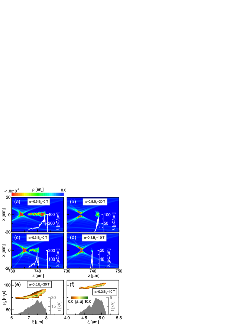
From the above analysis, it is evident that electron injection can be flexibly controlled by the combination of a density down-ramp and a magnetic field . The density down-ramp triggers the electron injection, while the magnetic field suppresses the injection. The required to suppress the injection decreases with decreasing plasma density because the radius of the hole in the open bubble rear is inversely proportional to [32]. Figures 4(a) and 4(b) illustrate that a weaker magnetic field can suppress injection for a lower density , where the corresponding length of injected electron bunch is reduced from to . The required for suppressing injection can be further reduced by reducing the plasma density gradient. Figures 4(c) and 4(d) illustrate that electron injection can be effectively suppressed by T if a more gentle down-ramp is adopted (), which is also more feasible experimentally. Figures 4(e) and 4(f) show the phase-space distributions and currents of the ultrashort electron bunches presented in figures 4(b) and 4(d), respectively. These quasi-monoenergetic electron bunches have charges of pC and RMS durations of fs, which corresponds to peak currents kA, respectively. Their emittances are as low as m and m, respectively.
4 Conclusion
In summary, sub-femtosecond electron bunches with a few pC in charge are accessible in the LWFA if electron injection is finely controlled by 3D manipulation of the plasma bubble. Combining a plasma density gradient with an external magnetic field, not only modulates the bubble velocity but also the electron longitudinal velocity. In this 3D manipulation, the increase of the bubble length along the density down-ramp increases the electron energy around the bubble rear, which results in electron injection, while an expanding hole in the bubble rear suppresses injection. The latter is attributed to the centrifugal force, which is proportional to the electron energy. The expanding hole will in return reduce the electron energy around the bubble rear. As a result, prompt suppression of electron injection is achieved. This 3D manipulation of the plasma bubble may enable realisation of sub-femtosecond electron bunches with readily accessible parameters both for density profiles and magnetic field strength. Furthermore, it may be extended to generate electron bunches with narrow energy spreads since the electrons can be properly phased in the wake and beam loading can be compensated as long as the electron injection is suppressed at a proper time [25].
Acknowledgments
We thank F. Y. Li for fruitful discussions. The work was supported by the National Basic Research Program of China (Grant No. 2013CBA01504), National Natural Science Foundation of China (Grant Nos. 11675108, 11774227, 11721091, and 11655002), National 1000 Youth Talent Project of China, UK Engineering and Physical Sciences Research Council (EPSRC) (Grant No. EP/N028694/1), the European Union’s Horizon 2020 research and innovation programme under grant agreements 654148 Laserlab-Europe and 653782 EuPRAXIA.
References
References
- [1] Tajima T and Dawson J M 1979 Phys. Rev. Lett. 43 267
- [2] Esarey E, Schroeder C B and Leemans W P 2009 Rev. Mod. Phys. 81 1229
- [3] Pukhov A and Meyer-Ter-Vehn J 2002 Appl. Phys. B 74 355
- [4] Lu W, Huang C, Zhou M, Tzoufras M, Tsung F S, Mori W B and Katsouleas T 2006 Phys. Plasmas 13 056709
- [5] Yi S A, Khudik V, Siemon C and Shvets G 2013 Phys. Plasmas 20 013108
- [6] Jaroszynski D A and Vieux G 2002 Adv. Accelerator Concepts 647 902; Clayton C E and Muggli P Eds. 2002 in 10th Workshop on Advanced Accelerator Concepts pp 902-913 Mandalay Beach Ca; Jaroszynski D A et al 2006 Phil. Trans. R. Soc. A 364 689
- [7] Rousse A, Phuoc K T, Shah R et al 2004 Phys. Rev. Lett. 93 135005
- [8] Schlenvoigt H P, Haupt K, Debus A et al 2008 Nat. Phys. 4 130
- [9] Fuchs M, Weingartner R, Popp A et al 2009 Nat. Phys. 5 826
- [10] Cipiccia S, Islam M R, Ersfeld B et al 2011 Nat. Phys. 7 867
- [11] Ersfeld B, Bonifacio R, Chen S, Islam M R, Smorenburg P W and Jaroszynski D A 2014 New J. Phys. 16 093025
- [12] Chen M, Luo J, Li F Y, Liu F, Sheng Z M and Zhang J 2016 Light Sci. Appl. 5 e16015
- [13] Faure J, Rechatin C, Norlin A, Lifschitz A, Glinec Y and Malka V 2006 Nature 444 737
- [14] Lundh O, Lim J, Rechatin C 2011 Nat. Phys. 7 219
- [15] Kärtner F X, Ahr F, Calendron A L et al 2016 Nucl. Instrum. Methods Phys. Res. A 829 24
- [16] Dorda U, Assmann R, Brinkmann R et al 2016 Nucl. Instrum. Methods Phys. Res. A 829 233
- [17] Morimoto Y and Baum P 2018 Nat. Phys. 14 252 M.
- [18] Hassan M Th 2018 J. Phys. B: At. Mol. Opt. Phys. 51 032005
- [19] Buck A, Nicolai M, Schmid K, Sears C M S, Savert A, Mikhailova J M, Krausz F, Kaluza M C and Veisz L 2011 Nat. Phys. 7 543
- [20] Heigoldt M, Popp A, Khrennikov K, Wenz J, Chou S W, Karsch S, Bajlekov S I, Hooker S M and Schmidt B 2015 Phys. Rev. ST Accel. Beams 18 121302
- [21] Islam M R, Brunetti E, Shanks R P et al 2015 New J. Phys. 17 093033
- [22] Li F Y, Sheng Z M, Liu Y, Meyer-ter-Vehn J, Mori W B, Lu W and Zhang J 2013 Phys. Rev. Lett. 110 135002
- [23] Bulanov S, Naumova N, Pegoraro F and Sakai J 1998 Phys. Rev. E 58 R5257
- [24] Geddes C G R, Nakamura K, Plateau G R, Toth C, Cormier-Michel E, Esarey E, Schroeder C B, Cary J R and Leemans W P 2008 Phys. Rev. Lett. 100 215004
- [25] Gonsalves A J, Nakamura K, Lin C et al 2011 Nat. Phys. 7 862
- [26] Hansson M, Aurand B, Davoine X, Ekerfelt H, Svensson K, Persson A, Wahlström C G and Lundh O 2015 Phys. Rev. ST Accel. Beams 18 071303
- [27] Martinez de la Ossa A, Hu Z, Streeter M J V, Mehrling T Kononenko J O, Sheeran B and Osterhoff J 2017 Phys. Rev. Accel.Beams 20 091301
- [28] Xu X L, Li F, An W, Dalichaouch T N, Yu P, Lu W, Joshi C and Mori W B 2017 Phys. Rev. Accel. Beams 20 111303
- [29] Tooley M P, Ersfeld B, Yoffe S R, Noble A, Brunetti E, Sheng Z M, Islam M R and Jaroszynski D A 2017 Phys. Rev. Lett. 119 044801
- [30] Hosokai T, Kinoshita K, Zhidkov A Maekawa A, Yamazaki A and Uesaka M 2006 Phys. Rev. Lett. 97 075004; Hosokai T et al 2010 Appl. Phys. Lett. 96 121501
- [31] Vieira J, Martinss S F, Pathak V B Fonseca R A, Mori W B and Silva L O 2011 Phys. Rev. Lett. 106 225001; Vieira J et al 2012 Plasma Phys. Control. Fusion 54 124044
- [32] Bulanov S V, Esirkepov T Zh, Kando M, Koga J K, Hosokai T, Zhidkov A G and Kodama R 2013 Phys. Plasmas 20 083113
- [33] Rassou S, Bourdier A and Drouin M 2015 Phys. Plasmas 22 073104
- [34] Zhao Q, Weng S M, Sheng Z M, Chen M, Zhang G B, Mori W B, Hidding B, Jaroszynski D A and Zhang J 2018 New J. Phys. 20 063031
- [35] Pollock B B, Froula D H, Davis P F et al 2006 Rev. Sci. Instrum. 77 114703
- [36] Fiksel G, Agliata A, Barnak D et al 2015 Rev. Sci. Instrum. 86 016105
- [37] Shi Y, Vieira J, Trines R M G M, Bingham R, Shen B F and Kingham R J 2018 Phys. Rev. Lett. 121 145002
- [38] Tsakiris G D, Gahn C and Tripathi V K 2000 Phys. Plasmas 7 3017
- [39] Fonseca R A, Silva L O, Tsung F S et al Lect. Not. Comput. Sci. 2331 342
- [40] Kononenko O, Lopes N, Cole J et al 2016 Nucl. Instrum. Methods Phys. Res. Sect. A 829 125