Magnetically driven loss of centrosymmetry in metallic Pb2CoOsO6
Abstract
We report magnetic, transport, neutron diffraction, and muon spin rotation data showing that Pb2CoOsO6, a newly synthesized metallic double-perovskite with a centrosymmetric space group at room temperature, exhibits a continuous second-order phase transition at 45 K to a magnetically ordered state with a non-centrosymmetric space group. The absence of inversion symmetry is very uncommon in metals, particularly metallic oxides. In contrast to the recently reported ferroelectric-like structural transition in LiOsO3, the phase transition in Pb2CoOsO6 is driven by a long-range collinear antiferromagnetic order, with propagation vector , which relieves the frustration associated with the symmetry of themagnetic exchanges. This magnetically-driven loss of inversion symmetry represents a new frontier in the search for novel metallic behavior.
pacs:
77.80.-e, 72.80.Ga, 77.80.B-, 75.47.LxI Introduction
Metals whose crystal structure lacks a center of inversion symmetry have been attracting increasing interest owing to the novel phenomena they can exhibit, such as optical activity Mineev and Yoshioka (2010) and a highly anisotropic thermopower, (a desirable property of certain thermoelectric devices) Puggioni and Rondinelli (2014). Non-centrosymmetric metals having strong electronic correlations can support exotic emergent quasiparticles, including skyrmions in chiral magnets Mühlbauer et al. (2009). Non-centrosymmetric superconductors are of particular interest because they can have spin-polarized supercurrents and unconventional pairing states with mixed singlet-triplet character even in the absence of strong electronic correlations Fujimoto (2007); Bauer and Sigrist (2012); Samokhin (2015). The key feature of non-centrosymmetric systems is a band splitting throughout much of momentum space caused by spin–orbit coupling (Dresselhaus splitting Dresselhaus (1955)) which leads to a non-trivial topology of the electronic wave functions and plays an essential role in all these phenomena.
Non-centrosymmetric metals (NCSM) are relatively uncommon. This is because conduction electrons can effectively screen the electric dipole formation which is generally associated with acentricity. In fact, there exist to date only around 30 known NCSM, of which only a handful are metallic oxides Puggioni and Rondinelli (2014). Nevertheless, oxides are particularly attractive for device applications due to their stability under typical operating conditions, so the discovery of more oxide NCSM would be of considerable interest.
Structural transitions in metallic oxides which remove the center of inversion symmetry have previously been observed in Cd2Re2O7 Sergienko et al. (2004) and LiOsO3 Shi et al. (2013). The origin and nature of the transition in Cd2Re2O7 is uncertain, but LiOsO3 was found to be an example of what Anderson and Blount referred to as a “ferroelectric metal”, i.e. a metal having a continuous structural phase transition accompanied by the appearance of a polar axis and the disappearance of an inversion centre Anderson and Blount (1965). The phase transition in LiOsO3 is driven by the ordering of Li ion displacements Shi et al. (2013).
Here, we report structural, magnetic and transport measurements of Pb2CoOsO6, another metal that undergoes a phase transition to a non-centrosymmetric structure. In this case, however, we show that the loss of inversion symmetry is driven by magnetoelastic coupling to a pair of antiferromagnetic order parameters which relieve the magnetic frustration of the higher symmetry phase, analogous to the behavior of a type-II hybrid-improper multiferroic Benedek and Fennie (2011); Stroppa et al. (2013). This represents a new paradigm for obtaining NCSM using magnetic frustration as a key ingredient.
II Structural and bulk characterisation
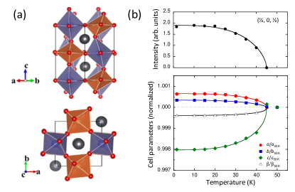
Polycrystalline and single crystal Pb2CoOsO6 was prepared by a high pressure method (see Supplementary Materials). The room temperature crystal structure of polycrystalline Pb2CoOsO6 was initially determined by synchrotron X-ray diffraction (XRD) (see Supplementary Materials). The structure found is the fully ordered double perovskite structure with space group of P21/ (tilt pattern a-a-c+ in the notation of Glazer Glazer (1972)). The Co and Os atoms fully occupy the Wyckoff positions 2a and 2b, respectively, with no site mixing observed to the accuracy of the measurement. The bond valence sums imply +2 and +6 valence states for the Co and Os atoms respectively Ederer et al. (2011); Azuma et al. (0015). The refined crystal structure is depicted in Fig. 1(a). The degree of distortion from the cubic structure is indicated by the deviation of inter-octahedral Co-O-Os bond angles which are 180∘ in the ideal structure, but here we find them to be 168∘, 172∘, and 145∘, respectively, implying substantial buckling of the octahedral connections.
The temperature variation of the structure of Pb2CoOsO6 was investigated between 1.5 K and 300 K by neutron powder diffraction (NPD). Neutron diffraction experiments were performed on a 4g powder at the ISIS facility on the WISH diffractometer. Rietveld refinements were carried out using the FullProf suite Rodriguez-Carvajal (1993) using the magnetic form factor for Os6+ determined by Kobayashi et. al. Kobayashi et al. (1991). Results of refinement against the NPD pattern at 300 K are fully consistent with the synchrotron XRD results, including the absence of any Co/Os site mixing to within the experimental uncertainty of 1%. The lattice parameters decrease monotonically with temperature below 300 K until = 45 K, below which the parameters and increase slightly while decreases significantly for a small net reduction in the unit-cell volume [see Fig. 1(b)]. This abrupt change in behavior of the lattice parameters is typically indicative of a magnetoelastic structural distortion accompanying the magnetic order, as discussed below. We identify with a bulk antiferromagnetic ordering transition, based on the neutron diffraction and muon spin rotation experiments presented below, as well as by the existence of characteristic signatures in other physical properties (see Fig. 2).
Fig. 2(a) presents the temperature dependence of the electrical resistivity of Pb2CoOsO6 measured on a single crystal between 2 K and 300 K. The single crystal was confirmed to have the same crystal structure as the powder sample by single crystal XRD (see Supplementary Materials and Fig. S2). Above , is roughly linear in , and displays a pronounced change at TN without fundamentally altering its metallic character. The drop in below is likely due to the reduction in scattering of the conduction electrons by paramagnetic fluctuations as the system undergoes magnetic ordering. At the lowest temperatures there is a small upturn in the resistivity, however given the resistivity decreases monotonically over several decades in temperature and there is no evidence for a further transition we attribute this to a simple experimental artefact arising from the contacts with the sample. The dc magnetic susceptibility ( vs. ) of Pb2CoOsO6, presented in Fig. 2(b), exhibits a sharp peak at , implying that the transition has a magnetic origin. A Curie-Weiss fit to in the paramagnetic region above 200 K (see Fig. S2a in Supplementary Materials) yields the Weiss temperature 106 K, suggesting dominant antiferromagnetic (AFM) interactions and a / , indicative of weak magnetic frustration. The effective magnetic moment () per formula unit is approximately 4.9 .
III Magnetic structure refinement
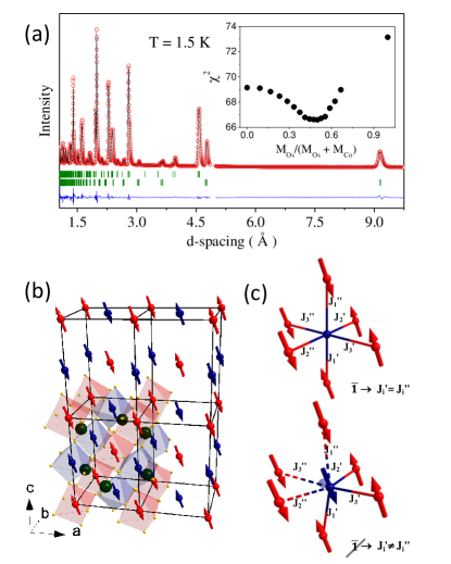
Below , additional peaks were observed in NPD patterns that could be indexed with a propagation vector [see Fig. 1(b) upper and Fig. 3(a)]. There are four magnetic irreducible representations (irreps) that are compatible with in the space group P21/ and these are the 1-dimensional irreps mY, mY, mY, and mY Miller and Love (1967). The “+” type irreps correspond to order on only the Co sites, and the “–” irreps to order on only the Os sites, and each irrep has a specific relation between the direction of the moments on the two equivalent metal sites. The allowed magnetic Bragg reflections vary with the choice of irrep, and inspection of the NPD data allowed us to constrain the possible irreps to mY and mY. A model combining these two irreps was refined against NPD data from banks 2-9 of WISH. Fig. 3(a) shows data from banks 2 and 9 recorded at 1.5 K together with the refinement. The results of the refinement are tabulated in Table 1, and the magnetic structure is shown in Fig. 3(b). A direct observation of the loss of centrosymmetry by measuring of optical second harmonic generation or Friedel pairs would be unlikely to be fruitful, as the size of the distortion is likely to be as large or smaller than that in magnetically induced (type-II) multiferroics where a similar mechanism pertains. There, the size of the polar distortion is of order 10fm (i.e. the atomic nucleus) and thus far too small to detect by standard methods Walker et al. (2011).
The parameters describing the Co and Os moments are strongly correlated in the refinement and constraints are needed to reach convergence. This is specific to in the space group P21/ where both magnetic atoms contribute intensity to the reflections in the exact same way except for their different form factors. Initial refinements performed with moments on only the Co sites or only the Os sites indicated that the magnetic structure is collinear and that the component along the -axis () is undetectably small. Thereafter, we set to zero and performed fits as a function of the ratio of the moments on the Co and Os sites assuming all moments to be collinear. The substantial difference between the magnetic form factors of Co2+ and Os6+ provides a degree of sensitivity to the magnetic moment on each sublattice, and the best fit was found with approximately the same moment (2.04 ) on both Co and Os sites inclined at an angle of about 22 deg to the c axis. Fig. 3(a) shows data from banks 2 and 9 recorded at 1.5 K together with the refinement, and the insert shows the fit quality as the Os moment fraction is varied. The results of the refinement are tabulated in Table 1, and the magnetic structure is shown in Fig. 3(b).
The observation of a single magnetic transition indicates coincident order of the two sub-lattices, as observed recently in the osmate double-perovskite Sr2FeOsO6 Paul et al. (2013). Coincident order of coupled sublattices is to be expected unless the Co-O-Os superexchange was either highly frustrated or suppressed, in which case one expects two distinct magnetic transitions as appears to be the case in Sr2CoOsO6 Morrow et al. (2013); Yan et al. (2014). It is worthing that the conclusions of the preceding symmetry analysis are not contingent on a single magnetic phase transition. If in reality one of the magnetic sublattices orders at some temperature T just below the resulting state would still be without a centre of symmetry and thus a magnetically driven polar metal.
As was noted earlier, below the temperature dependence of the lattice parameters abruptly changes and they display an order-parameter-like behavior, suggesting that the lattice distortion is coupled to the magnetic order parameter. The magnetic structure refinement and electronic structure calculations (see below) provide evidence that there are ordered moments on both the Co and Os sites, and moreover, the refined magnetic structure does not possess a centre of symmetry. Any non-zero magneto-elastic coupling will then remove the centre of symmetry of the crystal structure, Fig. 3(c), relieving frustration and reducing the space group symmetry of the structure to the (non-centrosymmetric) polar group P iso , with the corresponding Shubnikov group for the magnetic structure being Pac. Both Co and Os have a non-zero orbital angular momentum and so such coupling is expected to be non-negligible, and is indicated by the temperature-dependent variation of the lattice parameters described earlier [see Fig. 1(a)]. This scenario is opposite to the case where relieving orbital degeneracy results in a structural phase transition (i.e. a Jahn-Teller transition) for which any eventual magnetic ordering is expected to occur at a lower temperature Kugel and Khomskii (1982). Instead, the onset of magnetic order, via spin-orbit coupling, enforces some preferred orbital occupation which then results in a structural distortion Kugel and Khomskii (1982) as is the case, for example, at in Sr2CoOsO6 Morrow et al. (2013); Yan et al. (2014). Although clear changes in structural elements of the diffraction pattern were observed on cooling through , it proved impossible to refine a detailed model for the low temperature crystal structure owing to instabilities that resulted from the large number of free parameters.
| Site | Wyck | (Å2) | |||
| Pb | 4e | 0.0059(3) | 0.5127(4) | 0.2504(3) | 0.45(4) |
| Co | 2a | 0 | 0 | 0 | 0.09(17) |
| Os | 2b | 0 | 0 | 0.5 | 0.18(6) |
| O1 | 4e | -0.0679(4) | -0.0088(7) | 0.2592(4) | 0.53(6) |
| O2 | 4e | 0.2413(6) | 0.2810(7) | 0.0362(8) | 0.55(12) |
| O3 | 4e | 0.2834(6) | 0.7651(6) | 0.0365(8) | 0.50(12) |
| Site | Ma | Mb | Mc | irrep | |
| Co | -0.77(1) | 0 | 1.89(1) | mY | |
| Os | -0.77(1) | 0 | 1.89(1) | mY |
IV Electronic Structure Calculations
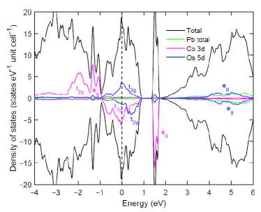
The electronic structure of Pb2CoOsO6 was investigated by performing first-principles calculations with the OpenMX software package ope using the lattice parameters and the AFM configuration obtained from the NPD refinement. The choice of pseudo-potentials, basis sets and the sampling of Brillouin zone with 6610 grid have been carefully optimized and the exchange-correlation functional within the generalized gradient approximation (GGA) Perdew et al. (1996) was used. For Co 3 orbitals, the spin splitting is larger than that due to the CF, so that Co2+ is in its high spin state with configuration as t e t e , where the superscript number represents the number of occupied electrons and arrows indicate the spin state. On the contrary, the extended 5 orbitals of Os have a larger CF splitting than spin splitting, which consequently results in a low spin state of Os6+ (5) with an approximate configuration of t e t e . The calculated density of states (DOS) indicates substantial contributions from both Co and Os -electrons at the Fermi level, both of which are split into t2g and eg manifolds under the approximately octahedral crystal field (CF). This large density of states at the fermi level is consistent with the robust metallicity we observe experimentally. The calculated local magnetic moments inferred from this are 2.46 and 0.450 , on Co and Os respectively, consistent with the above approximate atomic configuration and with the range of possible experimental values indicated by NPD [see insert to Figure 3(a)].
V Muon Spin rotation and DFT+
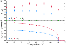
The scenario of a magnetically-induced structural distortion described above requires magnetic order on both the Co and Os sublattices. As a further test of this picture we turned to zero-field muon-spin rotation (SR), which is a local probe of magnetism. Zero-field (ZF) muon spin relaxation ( SR) spectra of Pb2CoOsO6 were measured in a 3He cryostat in the General Purpose Spectrometer (GPS) at the Swiss Muon Source at the Paul Scherrer Institute, Switzerland. The muon spectra (Figure 6, blue curve) below the transition can be well modelled with the equation
| (1) |
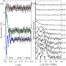
The first two terms of Eq. 1 represent muons stopping in the sample and experiencing long-range magnetic order with precession frequencies and relaxation rates , where is the muon muon gyromagnetic ratio and are the local fields. The third term accounts for muons stopping outside the sample, such as in the sample holder. The results for and are plotted in Figure 6, together with phenomenological order parameter models of the form from which a critical temperature of K can be extracted. Furthermore, the ratios of the amplitudes averaged over the measured temperatures below indicate that about 35% of the muons in our experiments experienced the smaller magnetic field, about 60% the higher field, and about 5% implanted outside the sample.
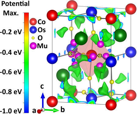
In order to compare the observed muon precession frequencies with ones predicted from different magnetic structures, it is necessary to establish the potential muon stopping sites in Pb2CoOsO6. To this end we employed Density Functional Theory (DFT) calculations using the plane-wave program Quantum Espresso Gianozzi et al. (2009) within the generalized gradient approximation (GGA) Perdew et al. (1996). We modelled the ions with ultrasoft pseudopotentials Rappe et al. (1990) and the muon with a norm-conserving hydrogen pseudopotential. The energy cutoffs for the wavefunction and the charge density were set to Ry and Ry, respectively, and a Monkhorst-Pack -space grid Monkhorst and Pack (1976) was used for the integration over the Brillouin zone. Within these parameters the calculations gave well converged results and reproduced the experimentally observed atomic positions and lattice parameters within a 1% accuracy. The results shown in Figure 7 were visualised with the Vesta software Momma and Izumi (2008).
We use the converged electron density to map out the electrostatic Coulomb potential of Pb2CoOsO6 throughout its unit cell, as plotted in Figure 7. The global maximum is used as the reference point, since large values of the Coulomb potential correspond to a low energy cost to add a positive charge and such regions have been found to be a reliable first-order estimate of potential muon sites Möller et al. (2013); Foronda et al. (2015). Addtionally, we performed relaxation calculations, which allow for distortions of the lattice due to the implanted muon, which lead to muon site candidates in good agreement with the sites predicted by the local maxima of the electrostatic potential. In fact, we find that there are eight potential muon site candidates, which are all fairly closely related in energy and symmetry due to the proximity of the crystal structure of Pb2CoOsO6 to a more symmetric cubic one. These muon sites, plotted in Figure 7 and tabulated in Table 2, are also all characterised by an O–H like bond between the muon and an oxygen with a bond length of about , which is a typical occurence in oxygen containing compounds Möller et al. (2013); Foronda et al. (2015).
The muon asymmetry, plotted in Figure 5(a) for three temperatures, exhibits an oscillatory beating pattern at low temperatures indicative of long-range magnetic ordering. The Fourier transform spectra of the ZF-SR asymmetries, presented in Figure 5(b), reveals two broad peaks centered around muon precession frequencies of roughly 30 MHz and 55 MHz at the lowest measured temperatures which vanish above the transition temperature. Likely muon stopping sites in the magnetic unit cell were calculated using DFT methods, and we find 8 possible muon stopping sites with comparable energies, which could thus potentially be occupied. We label these sites Mu1-8 in order of increasing enregy cost for occupation and thus decreasing probability of occupation.
| Site | Relaxed position | E/u.c. | O–H | ||
|---|---|---|---|---|---|
| Label | x | y | z | (meV) | with |
| Mu1 | 0.786 | 0.225 | 0.838 | 0 | O3 |
| Mu2 | 0.264 | 0.720 | 0.334 | 4.5 | O2 |
| Mu3 | 0.295 | 0.878 | 0.026 | 6.5 | O3 |
| Mu4 | 0.878 | 0.699 | 0.983 | 24.5 | O2 |
| Mu5 | 0.880 | 0.288 | 0.988 | 24.8 | O3 |
| Mu6 | 0.305 | 0.121 | 0.015 | 40.5 | O2 |
| Mu7 | 0.710 | 0.291 | 0.403 | 46.6 | O2 |
| Mu8 | 0.710 | 0.711 | 0.407 | 46.8 | O3 |
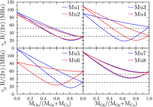
With the potential muon spotting sites from Table 2, we can calculate the local magnetic fields at each of these sites. Because our neutron experiments revealed an antiferromagnetic ordering the Lorentz and demagnetising fields are zero and since the muon sites are far from the Os and Co ions we also expect hyperfine field contributions to be negligible, such that we only have to focus on the dipolar fields
Here, the correspond to the relative positions of the magnetic moments with respect to the muon. Using the total moment size, as listed in Table 1, we computed the local magnetic fields, assuming a fraction of the total moment lies on the Os sites, while a fraction of the total moment lies on the Co sites, for each of the muon site candidates and their 16 symmetry equivalent sites in the magnetic unit cell. The resulting muon precession frequencies are plotted in Figure 8. Note that each line in Figure 8 actually represents eight nearly identical lines, such that the 16 positions symmetry equivalent to the Mu1 site actually only lead to two distinct experimentally observable frequencies (unless the Os moment fraction is very close to 0 or 1). We can further note that the local fields at some of the muon stopping sites are almost identical, which is owed to the proximity to a cubic crystallographic symmetry (see Figure 7). Based on the muon precession frequencies shown in Figure 8 we can identify two scenarios which can plausibly explain our experimentally observed frequencies. Either, only the two energetically most favourable sites (Mu1 and Mu2) are significantly occupied and that . Alternatively, all eight of the identified muon site candidates might be occupied and . Both scenarios would lead to only two experimentally distinguishable frequencies, with a ratio of the oscillation amplitudes of these two frequencies expected in the region of 1:1, very roughly in line with that observed experimentally.
VI Discussion
Of the two realistic possibilities outlined above, the scenario with (i.e. the full moment is on the osmium site) is very unlikely. First, this scenario would require that the cobalt fails to order, contrary to other known double perovskites of mixed 3-5 cations, in which the 3 cation is either the only element that orders or the first to order by a significant margin. Second, the Os6+ in Pb2CoOsO6 would have to carry a moment (approx 4) substantially greater than that which has been observed in any osmium containing compound to date; and indeed greater than should be possible even for an ideal case (giving 3.6), which anyway does not seem to be favoured for Os due to covalency effects that are substantial compared to 3d and even 4d elementsGangopadhyay and Pickett (2015); Taylor et al. (2015); Thompson et al. (2014). The likelihood of such a large moment on Os is further diminished by recent results on other 5 osmium double-perovskites Ba2CaOsO6 (ordered moment 0.2 Thompson et al. (2014)), Sr2CoOsO6 (ordered moment 1.8 Morrow et al. (2013); Yan et al. (2014)), Ca3OsO6 (moment estimated from curie–weiss fit 2 Feng et al. ), and both Sr2MgOsO6 and Ca2MgOsO6 (ordered moment 1.8Yuan et al. (2015)). The weight of evidence overwhelmingly suggests that both the Os and Co ions carry an ordered moment in the magnetically ordered phase.
VII Conclusion
We conclude that the antiferromagnetic phase transition in Pb2CoOsO6, involving the simultaneous magnetic order on both the Co and Os sublattices, removes the centre of crystal symmetry and through magnetoelastic coupling relaxes the structure into the polar multiferroic Shubnikov group Pac. In Pb2CoOsO6, the spin-driven nature of the structural transition is reminiscent of a type-II hybrid improper multiferroic transition, in which magnetic order removes inversion symmetry via some higher order invariant in the free energy Benedek and Fennie (2011); Stroppa et al. (2013). A key difference between the present case and all known multiferroics, however, is that the transition in Pb2CoOsO6 occurs entirely in the metallic state. Oxide NCSMs are still very rare, and the materials known up to now exist because the polar displacements are almost entirely decoupled from the conduction electrons. The magnetic mechanism for acentricity in Pb2CoOsO6 does not suffer from this constraint and could provide a new route for the discovery of other oxide NCSMs and their associated novel phenomena. Thus, the phase transition we have illustrated in Pb2CoOsO6 could provide a new guiding principle for the future discovery of oxide NCSMs.
VIII Acknowledgments
Two authors (AJP and HLF) contributed equally to this work. This research was supported in part by the World Premier International Research Center from MEXT; the Grants-in-Aid for Scientific Research (25289233) from JSPS; the Funding Program for World-Leading Innovative R&D on Science and Technology from JSPS; and United Kingdom Engineering and Physical Sciences Research Council (EPSRC). H.M.W. acknowledges the supports from NSF of China and the 973 program of China (No. 2011CBA00108 and 2013CB921700). YFG acknowledges the support of Shanghai Pujiang Program, grant No. 17PJ1406200. We performed the SXRD measurements with the approval of the NIMS beamline station (Proposal No. 2013B4503). This work was supported by EPSRC (UK) grants EP/N034872 and EP/N023803. The authors acknowledge the use of the University of Oxford Advanced Research Computing (ARC) facility (http://dx.doi.org/10.5281/zenodo.22558).
References
- Mineev and Yoshioka (2010) V. P. Mineev and Y. Yoshioka, Phys. Rev. B 81, 094525 (2010).
- Puggioni and Rondinelli (2014) D. Puggioni and J. M. Rondinelli, Nat. Commun 5, 3432 (2014).
- Mühlbauer et al. (2009) S. Mühlbauer, B. Binz, F. Jonietz, C. Pfleiderer1, A. R. A. Neubauer, R. Georgii, and P. Böni, Science 323, 915 (2009).
- Fujimoto (2007) S. Fujimoto, J. Phys. Soc. Jpn. 76, 051008 (2007).
- Bauer and Sigrist (2012) E. Bauer and M. Sigrist, Non-Centrosymmetric Superconductors: Introduction and Overview (Springer, Heidelberg, 2012).
- Samokhin (2015) K. V. Samokhin, Annals of Physics 359, 385 (2015).
- Dresselhaus (1955) G. Dresselhaus, Phys. Rev. 100, 580 (1955).
- Sergienko et al. (2004) I. A. Sergienko, V. Keppens, M. McGuire, R. Jin, J. He, S. H. Curnoe, B. C. Sales, P. Blaha, D. J. Singh, K. Schwarz, and D. Mandrus, Phys. Rev. Lett. 92, 065501 (2004).
- Shi et al. (2013) Y. Shi, Y. Guo, X. Wang, A. J. Princep, D. Khalyavin, P. Manuel, Y. Michiue, A. Sato, K. Tsuda, S. Yu, M. Arai, Y. Shirako, M. Akaogi, N. Wang, K. Yamaura, and A. T. Boothroyd, Nat. Mater. 12, 1024 (2013).
- Anderson and Blount (1965) P. W. Anderson and E. I. Blount, Phys. Rev. Lett. 14, 217 (1965).
- Benedek and Fennie (2011) N. A. Benedek and C. J. Fennie, Phys. Rev. Lett. , 107204 (2011).
- Stroppa et al. (2013) A. Stroppa, P. Barone, P. Jain, J. M. Perez‐Mato, and S. Picozzi, Adv. Mater. , 2284 (2013).
- Glazer (1972) A. M. Glazer, Acta Cryst B 28, 3384 (1972).
- Ederer et al. (2011) C. Ederer, T. Harris, and R. Kovác̆ik, Phys. Rev. B 83, 054110 (2011).
- Azuma et al. (0015) M. Azuma, K. Takata, T. Saito, S. Ishiwata, Y. Shimakawa, and M. Takano, J. Am. Chem. Soc. 127, 8889 (20015).
- Rodriguez-Carvajal (1993) J. Rodriguez-Carvajal, Physica B 192, 55 (1993), http://www.ill.eu/sites/fullprof/.
- Kobayashi et al. (1991) K. Kobayashi, T. Nagao, and M. Ito, Acta Cryst. A 67, 473 (1991).
- Miller and Love (1967) S. C. Miller and W. F. Love, Tables of Irreducible Representations of Space Groups and Co-Representations of Magnetic Space Groups (Boulder: Pruett, 1967).
- Walker et al. (2011) H. C. Walker, F. Fabrizi, L. Paolasini, F. de Bergevin, J. Herrero-Martin, A. T. Boothroyd, D. Prabhakaran, and D. F. McMorrow, Science 333, 1273 (2011).
- Paul et al. (2013) A. K. Paul, M. Reehuis, V. Ksenofontov, B. Yan, A. Hoser, D. M. Többens, P. M. Abdala, P. Adler, M. Jansen, and C. Felser, Phys. Rev. Lett. 111, 167205 (2013).
- Morrow et al. (2013) R. Morrow, R. Mishra, O. D. Restrepo, M. R. Ball, W. Windl, S. Wurmehl, U. Stockert, B. Büchner, and P. M. Woodward, J. Am. Chem. Soc. 135, 18824 (2013).
- Yan et al. (2014) B. Yan, A. K. Paul, S. Kanungo, M. Reehuis, A. Hoser, D. M. Többens, W. Schnelle, R. C. Williams, T. Lancaster, F. Xiao, J. S. Möller, S. J. Blundell, W. Hayes, C. Felser, and M. Jansen, Phys. Rev. Lett. 112, 147202 (2014).
- (23) “Isotropy software suite,” http://iso.byu.edu.
- Kugel and Khomskii (1982) K. I. Kugel and D. I. Khomskii, Sov. Phys. Usp. , 231 (1982).
- (25) “Open source package for material explorer,” http://www.openmx-square.org.
- Perdew et al. (1996) J. P. Perdew, K. Burke, and M. Ernzerhof, Phys. Rev. Lett. 77, 3865 (1996).
- Gianozzi et al. (2009) P. Gianozzi et al., J. Phys.: Cond. Matt. 21, 395502 (2009).
- Rappe et al. (1990) A. M. Rappe, K. M. Rabe, E. Kaxiras, and J. D. Joannopoulos, Phys. Rev. B 41, 1227 (1990).
- Monkhorst and Pack (1976) H. J. Monkhorst and J. D. Pack, Phys. Rev. B 13, 5188 (1976).
- Momma and Izumi (2008) K. Momma and F. Izumi, J. Appl. Chem. 41, 653 (2008).
- Möller et al. (2013) J. S. Möller, P. Bonfà, D. Ceresoli, F. Bernardini, S. J. Blundell, T. Lancaster, R. De Renzi, N. Marzari, I. Watanabe, S. Sulaiman, and M. I. Mohamed-Ibrahim, Physica Scripta 88, 068510 (2013).
- Foronda et al. (2015) F. R. Foronda, F. Lang, J. S. Möller, T. Lancaster, A. T. Boothroyd, F. L. Pratt, S. R. Giblin, D. Prabhakaran, and S. J. Blundell, Physical Review Letters 114, 017602 (2015).
- Gangopadhyay and Pickett (2015) S. Gangopadhyay and W. E. Pickett, Phys. Rev. B 91, 045133 (2015).
- Taylor et al. (2015) A. E. Taylor, R. Morrow, D. J. Singh, S. Calder, M. D. Lumsden, P. M. Woodward, and A. D. Christianson, Phys. Rev. B 91, 100406(R) (2015).
- Thompson et al. (2014) C. M. Thompson, J. P. Carlo, R. Flacau, T. Aharen, I. A. Leahy, J. R. Pollichemi, T. J. S. Munsie, T. Medina, G. M. Luke, and J. Munevar, J. Phys.: Condens. Matter 26, 306003 (2014).
- (36) H. L. Feng, Y. Shi, Y. Guo, J. Li, A. Sato, Y. Sun, X. Wang, S. Yu, C. I. Sathisha, and K. Yamaura, J. Solid State Chem. 201.
- Yuan et al. (2015) Y. Yuan, H. L. Feng, M. P. Ghimire, Y. Matsushita, Y. Tsujimoto, J. He, M. Tanaka, Y. Katsuya, and K. Yamaura, Inorg. Chem. 54, 3422 (2015).